SERVICE MANUAL for MODEL AirV Rooftop Air Conditioning Systems
SERVICE MANUAL for MODEL AirV Rooftop Air Conditioning Systems
SERVICE MANUAL for MODEL AirV Rooftop Air Conditioning Systems
- No tags were found...

You also want an ePaper? Increase the reach of your titles
YUMPU automatically turns print PDFs into web optimized ePapers that Google loves.
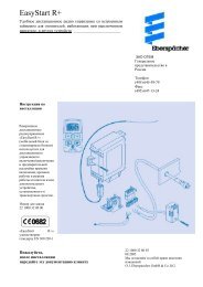
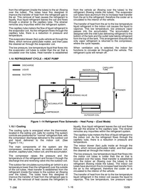
from the refrigerant (inside the tubes) to the air (flowingover the tubes). The tubes have fins designed toimprove the transfer of heat from the refrigerant gas tothe air. This removal of heat causes the refrigerant toliquefy, thus liquid refrigerant leaves the coil and flowsthrough a strainer to the capillary tube. The strainerremoves any impurities within the refrigerant system.The capillary tube meters the flow of liquid refrigerant tothe evaporator coil. As the refrigerant flows through thecapillary tube, there is a reduction in pressure andtemperature.The evaporator blower (fan) pulls vehicle air through thefilters, which remove particulate matter, and then passthe cleaned air through the evaporator coil.The low pressure, low temperature liquid that flows intothe evaporator coil tubes is colder than the air that iscirculated over the tubes. Heat transfer is establishedfrom the vehicle air (flowing over the tubes) to therefrigerant (flowing inside the tubes). The evaporatorcoil tubes have aluminum fins to increase heat transferfrom the air to the refrigerant; there<strong>for</strong>e the cooler air iscirculated to the interior of the vehicle.The transfer of heat from the air to the low temperatureliquid refrigerant in the indoor coil causes the liquid tovaporize. This low temperature, low pressure vaporpasses into the accumulator. The accumulator isdesigned with the inlet tube delivering refrigerant to thebottom of the tank and the outlet tube taking refrigerant<strong>for</strong>m the top of the tank. This arrangement ensures thatonly vapor refrigerant is returned to the compressor,where the cycle repeats.When ventilation only is selected, the indoor fanfunctions to circulate air throughout the vehicle. Therefrigerant cycle will remain off.1.10 REFRIGERANT CYCLE - HEAT PUMPDISCHARGELIQUIDSUCTIONINDOOR COILCAPILLARYTUBESTRAINERREVERSING VALVEACCUMULATORCOMPRESSOROUTDOOR COILFigure 1 -14 Refrigerant Flow Schematic - Heat Pump - (Cool Mode)1.10.1 CoolingThe cooling cycle is energized when the thermostat,located in the ceiling unit, calls <strong>for</strong> cooling The systemcontrols are positioned <strong>for</strong> “normal” refrigerant flow, withthe compressor discharge delivered to the outdoor coiland liquid delivered to the indoor coil. (SeeFigure 1--14.)The main components of the system are thecompressor, reversing valve, air-cooled outdoor coil,strainer, capillary tube, indoor coil, and the accumulator.The compressor raises the pressure and thetemperature of the refrigerant and <strong>for</strong>ces it through thedischarge line and reversing valve into the outdoor coil.The outdoor fan circulates surrounding air (which is at atemperature lower than the refrigerant) over the outsideof the coil tubes. Heat transfer is established from therefrigerant (inside the tubes) to the outdoor air (flowingover the tubes). The tubes have fins designed toimprove the transfer of heat from the refrigerant gas tothe air; this removal of heat causes the refrigerant toliquefy, thus liquid refrigerant leaves the coil and flowsthrough the strainer to the capillary tube. The strainerremoves any impurities within the refrigerant system.The capillary tube meters the flow of liquid refrigerant tothe indoor coil. As the refrigerant flows through thecapillary tube, there is a reduction in pressure andtemperature.The indoor blower (fan) pulls inside air through thefilters, which remove particulate matter, and then passthe cleaned air through the indoor coil.The low pressure, low temperature liquid that flows intothe indoor coil tubes is colder than the air that iscirculated over the tubes. Heat transfer is establishedfrom the indoor air (flowing over the tubes) to therefrigerant (flowing inside the tubes). The indoor coiltubes have aluminum fins to increase heat transfer fromthe air to the refrigerant; there<strong>for</strong>e the cooler air iscirculated to the interior of the vehicle.The transfer of heat from the air to the low temperatureliquid refrigerant in the indoor coil causes the liquid tovaporize. This low temperature, low pressure vaporT--298 1--16 10/09