SERVICE MANUAL for MODEL AirV Rooftop Air Conditioning Systems
SERVICE MANUAL for MODEL AirV Rooftop Air Conditioning Systems
SERVICE MANUAL for MODEL AirV Rooftop Air Conditioning Systems
- No tags were found...

Create successful ePaper yourself
Turn your PDF publications into a flip-book with our unique Google optimized e-Paper software.
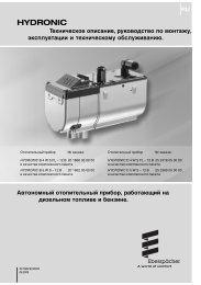
SECTION 1DESCRIPTION1.1 INTRODUCTIONThis manual contains service instructions and electricaldata <strong>for</strong> the <strong><strong>Air</strong>V</strong>, Carrier Transport <strong>Air</strong> <strong>Conditioning</strong>’sRecreational Vehicle air conditioning unit.The <strong><strong>Air</strong>V</strong> units are two piece systems, consisting of theUpper Unit and the Ceiling unit. The Upper Unit containsthe refrigeration system while the Ceiling Unit containsthe controls and vents. The Ceiling Units are available ina free--blow or ducted configuration.The free--blow units (see Figure 1--2) deliver air to thevehicle by means of front and rear end vents and onedownward vent (air shower). The vents may all beopened or closed to direct air as desired. The front andrear vents are fitted with motorized dampers thatoscillates to produce an “air--sweep” effect. These unitsmay be fitted with optional electric heat.The ducted units (see Figure 1--5 and Figure 1--10)deliver air through ducting built in the vehicle ceiling.These units are fitted with a 12 VDC microprocessorcontrol system, a display panel (PCB display) and aremote controller. These units may be wired to providethermostatic control of the vehicle furnace.Carrier’s <strong><strong>Air</strong>V</strong> air conditioning models include coolingonly units, heating/cooling units, and heat pump units.The cooling only units are available with free blow orducted air delivery. Cooling units with heat strips areavailable <strong>for</strong> free blow only.Operation of the <strong><strong>Air</strong>V</strong> units is controlled automatically bythe temperature controller (thermostat), whichmaintains the vehicle’s interior temperature at thedesired set point. Free Blow, cool--only units areavailable with a wall mounted thermostat.Table 1--1 lists Upper Unit <strong><strong>Air</strong>V</strong> model numbers anddescriptions. Table 1--2 lists Ceiling Unit modelnumbers and descriptions. Table 1--3 lists additionalsupport manuals that are available.1.2 SERIAL NUMBER IDENTIFICATIONSeparate part numbers and serial numbers are provided<strong>for</strong> the upper and lower unit assemblies The numbersmay be found on plates readable from inside the vehicle,See Figure 1--11 or Figure 1--12.The first two numbers of the serial number, seeFigure 3--23, is the week the unit was manufactured.For example, 01 would designate the first week of theyear and 52 would designate the last week of the year.The third and fourth numbers designate the year inwhich the unit was manufactured. For example, 99would represent the year 1999, 00 the year 2000, andso on.The letter Y and all the numbers after it designates theunit serial number. Example: Y43210A serial number of 1303Y12345 designates that the unitwas manufactured the 13th week of 2003 and the serialnumber is Y12345.<strong>MODEL</strong> No.Part No.VOLTS68RV14102A99 -00468 -01115 Vph 1 hz 60CAPACITY13,500 Btu/h3,955 W20 AMPAMPS 13.5 ATIME DELAY FUSE ORCIRCUIT BREAKER DATE OF MfgSERIAL No.05/031303Y12345DESIGN PSIG HIGH 350 LO 150R-22ozkg15.90.45COMPRESSORFAN MOTORRLAFLA12.52.58USE CEILING ASSY/ANY 99 -00469 -01Carrier<strong>Air</strong> <strong>Conditioning</strong>CDivision of Carrier CorporationUSEFigure 1 -1 Model/Serial Number Plate (Typical)1.3 DESIGN CHANGE DESCRIPTIONSThe following list provides a description of changes indesign and serial number breaks <strong>for</strong> those changes.0703Y (Power Assembly) & 1903Y (Control Assembly)New style PCB -- Cool Mode -- Control & PowerAssembly (Fans shut off in auto mode).0803Y (Power Assembly) & 2603Y (Control Assembly)New style PCB -- Heat Pump -- Control & PowerAssembly (Fans shut off in auto mode).4204Y Minimum furnace setpoint lowered from 63°Fto45°F.3808Y Changed standard profile blower wheel typefrom aluminum boss to ring compression type.10/091--1T--298