Model YCAV Air-Cooled Screw Compressor Liquid Chillers Style A
Model YCAV Air-Cooled Screw Compressor Liquid Chillers ... - DCES
Model YCAV Air-Cooled Screw Compressor Liquid Chillers ... - DCES

You also want an ePaper? Increase the reach of your titles
YUMPU automatically turns print PDFs into web optimized ePapers that Google loves.
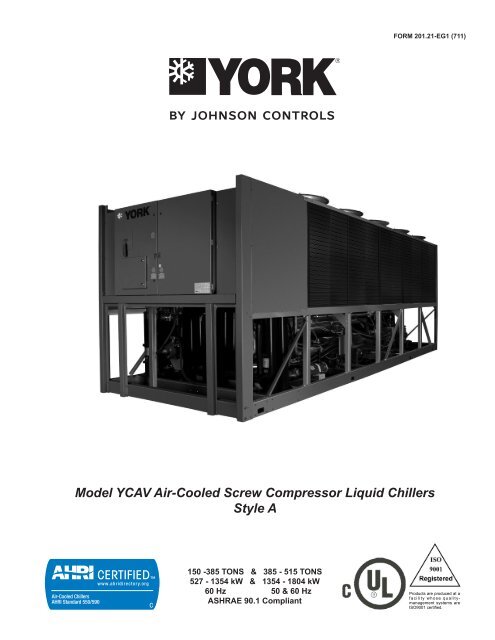
FORM 201.21-EG1 (711)<strong>Model</strong> <strong>YCAV</strong> <strong>Air</strong>-<strong>Cooled</strong> <strong>Screw</strong> <strong>Compressor</strong> <strong>Liquid</strong> <strong>Chillers</strong><strong>Style</strong> A150 -385 TONS & 385 - 515 TONS527 - 1354 kW & 1354 - 1804 kW60 Hz 50 & 60 HzASHRAE 90.1 CompliantProducts are produced at af a c i l i t y wh o s e qualitymanagementsystems areISO9001 certified.
Table of ContentsFORM 201.21-EG1 (711)FORM 201.21-EG1 (711)............................................................................................................................................................................................... 1Introduction.................................................................................................................................................................................................................. 3Specifications............................................................................................................................................................................................................... 4Accessories and Options ........................................................................................................................................................................................... 7Nomenclature............................................................................................................................................................................................................... 9Temperatures and Flows........................................................................................................................................................................................... 10Water Pressure Drop................................................................................................................................................................................................. 12Efficiency.................................................................................................................................................................................................................... 16Standard Efficiency Ratings - English - 60Hz......................................................................................................................................................... 18High Efficiency Ratings - English - 60Hz................................................................................................................................................................ 30Standard Efficiency Ratings - SI - 60Hz.................................................................................................................................................................. 40High Efficiency Ratings - SI - 60Hz.......................................................................................................................................................................... 46Standard Efficiency Ratings - SI - 50Hz................................................................................................................................................................... 52Standard Efficiency Ratings - SI - 50Hz - continued............................................................................................................................................... 54Standard Efficiency Ratings - SI - 50Hz - continued............................................................................................................................................... 56High Efficiency Ratings - SI - 50Hz........................................................................................................................................................................... 58High Efficiency Ratings - SI - 50Hz - continued...................................................................................................................................................... 60High Efficiency Ratings - SI - 50Hz - continued...................................................................................................................................................... 62Physical Data (English - Standard Efficiency)........................................................................................................................................................ 64Physical Data (English - High Efficiency)................................................................................................................................................................ 65Physical Data (SI - Standard Efficiency).................................................................................................................................................................. 68Physical Data (SI - High Efficiency).......................................................................................................................................................................... 69Dimensions - English................................................................................................................................................................................................. 72Dimensions - SI........................................................................................................................................................................................................ 104Isolator Details......................................................................................................................................................................................................... 136Electrical Data - 2 Comp - 60Hz.............................................................................................................................................................................. 140Electrical Data - 3 Comp - 60Hz.............................................................................................................................................................................. 144Electrical Data - 4 Comp - 60Hz.............................................................................................................................................................................. 146Electrical Data - 4 Comp - 50Hz.............................................................................................................................................................................. 150Electrical Notes........................................................................................................................................................................................................ 152Power Wiring............................................................................................................................................................................................................ 153Typical Control Wiring - Two <strong>Compressor</strong>............................................................................................................................................................ 158Typical Control Wiring - Three <strong>Compressor</strong>.......................................................................................................................................................... 160Typical Control Wiring - Four <strong>Compressor</strong>........................................................................................................................................................... 164Application Data....................................................................................................................................................................................................... 168Guide Specifications............................................................................................................................................................................................... 1692JOHNSON CONTROLS
IntroductionFORM 201.21-EG1 (711)YORK <strong>YCAV</strong> <strong>Air</strong> <strong>Cooled</strong> <strong>Screw</strong> <strong>Liquid</strong> <strong>Chillers</strong>Johnson Controls has a proud history of innovation in both compressor design and variable-speeddrive (VSD) technology. The Latitude TM air-cooled chiller uses the best of modern screw compressordesign and manufacturing techniques and combines them with the latest in a long line of chillervariable-speed drives. The result is superior control and industry leading efficiency at real worldconditions. In addition, by slowing the speed of the chiller to match system requirements at off-designconditions, the chiller sound output is reduced when it is the most sensitive to neighbors – eveningsand weekends.With the introduction of the YORK <strong>YCAV</strong> model air-cooled chiller, system designers are given theLatitude to design around the traditional benefits of air-cooled chillers and still offer building ownersenergy efficient system design. In the past, the choice to use an air-cooled chiller came with theexpectation of compromise, where simplicity of design and maintenance were traded for performanceand efficiency. Now combining the best of both worlds can provide a design that truly delivers thelowest total cost of ownership.JOHNSON CONTROLS3
FORM 201.21-EG1 (711)• External oil separators with no moving parts, 450 psig(31 barg) design working pressure, and UL listing.The refrigerant system differential pressure providesoil flow through a service replaceable, 0.5 micron, fullflow, cartridge-type oil filter internal to compressor.• Oil cooling provided by a dedicated air-cooled finnedtube type heat exchanger located in the condensersection of the machine.EVAPORATOR• The chiller uses a high efficiency, direct-expansiontype cooler with refrigerant in tubes and chilled liquidflowing through the baffled shell. Independent circuitsprovided for each compressor.• The design working pressure of the shell waterside is150 psig (10.3 barg), and 235 psig (16 barg) for therefrigerant side. The shell is constructed and tested inaccordance with applicable sections of ASME PressureVessel Code, Section VII, Division (1). The waterside exempt per paragraph U-1, (C), (6) of the ASMEPressure Vessel Code.• Removable heads on the cooler allow access tointernally-enhanced, seamless, copper tubes. Watervent and drain connections included.• The <strong>YCAV</strong> cooler is equipped with thermostaticallycontrolled heater for protection to -20°F (-29°C) ambient,and shell is covered with 3/4” (19mm), flexible,closed-cell insulation, thermal conductivity of 0.26kmaximum.• Cooler water nozzles have grooves for mechanicalcouplings. They are to be insulated by the Contractorafter pipe installation.CONDENSER SECTION• Fin and tube condenser coils of seamless, internallyenhanced, high condensing coefficient, corrosion resistantcopper tubes arranged in staggered rows andmechanically bonded to corrosion resistant aluminumalloy fins with full height fin collars. Design workingpressure is 450 psig (31 barg).• Low Sound Fans are provided standard on all models.Fans are dynamically and statically balanced, directdrive composite blades molded into low noise, fullairfoil cross section, providing vertical air dischargefrom extended orifices. Guards of heavy gauge, PVC(polyvinyl chloride) coated.• Condenser fan motors are high efficiency, directdrive, 3-phase, Class-“F” insulation, current overloadprotected, totally enclosed (TEAO) type with doublesealed, permanently lubricated, ball bearings.MICROPROCESSOR CONTROLS• Microprocessor control system provides automaticcontrol of chiller operation including compressor start/stop and load/unload anti-recycle timers, condenserfans, evaporator pump, evaporator heater, unit alarmcontacts and run signal contacts.• Chiller automatically resets to normal chiller operationafter power failure.• Unit operating software is stored in non-volatilememory. Field programmed set points are retained inlithium battery backed real time clock (RTC) memoryfor minimum 5 years.• Alarm contacts are provided to remote alert contactsfor any unit or system safety fault.• Display and Keypad:♦ An 80 character liquid crystal display that is bothviewable in direct sunlight and has LED backlightingfor nighttime viewing. The display is rated for200 nits. One keypad and display panel is providedwith every chiller.♦ Display and keypad is accessible through displayaccess door without opening main control/electricalcabinet doors.♦ Display provides unit setpoints, status, electricaldata, temperature data, pressures, safety lockoutsand diagnostics without the use of a coded display.♦ Control Panel readouts are displayed in English(or Spanish or French), while numeric data is presentedin English (or Metric) units.♦ Sealed keypad shall include unit On/Off switch.• Programmable Setpoints (within Manufacturer limits):display language; leaving chilled liquid temperature:setpoint, control range; local or remote control; units ofmeasure; compressor lead/lag; and maximum chilledwater setpoint reset temperature range.• Display Data: Chiller liquid return and leaving temperatures,ambient, lead compressor identification,clock and schedule, (variable) out of range, remoteinput indication, chilled liquid reset setpoint, and historydata for last ten shutdown faults. This includescompressor suction, discharge, and oil pressuresand temperatures, suction and discharge superheats,operating hours, starts, and anti-recycle timer status.Status Messages for manual override, unit switch off,compressor run, run permissive, remote controlledshut down, no cooling load, daily/holiday shut down,and anti-recycle timer.• During extreme or unusual conditions (i.e. blockedcondenser coils, ambient above scheduled maximum,etc.) the chiller control system will avoid safety shutdownby varying the chiller controls and cooling loadJOHNSON CONTROLS5
Specifications - continuedFORM 201.21-EG1 (711)output to stay online and avoid safety limits beingreached. This allows maximum possible cooling capacityuntil the unusual condition is cleared and avoidscostly shutdowns. The system monitors the followingparameters and maintains the maximum cooling outputpossible without shutdown of the equipment: motorcurrent, suction pressure and discharge pressure.• System Safeties are provided for individual compressorsystems to perform auto-reset shut down (manualreset required after the third trip in 90 minutes). Safetiesinclude: high discharge pressure or temperature,low suction pressure, high / low motor current, highmotor temperature, high pressure switch, high / lowdifferential oil pressure, high oil temperature, low suctionsuperheat, critical sensor malfunction, low or highcurrent, phase loss/single phase power, overload ofmotor windings, and low voltage.• Unit Safeties are provided for the chiller to performauto-reset shut down for the following conditions: highor low ambient, low leaving chilled liquid temperature,under voltage, and flow switch operation.COMPLETE FACTORY PACKAGE• These air-cooled chillers are shipped as a completefactory package. Each unit is completely assembledwith all interconnecting refrigerant piping and internalwiring, ready for field installation:• Each compressor is installed on its own independentrefrigerant circuit, which is factory pressure tested,evacuated, then fully charged with R134a refrigerantand oil.• After assembly, an operational test is performed withwater flowing through the cooler to ensure each circuitoperates correctly.• Unit panels, structural elements, control boxes andheavy gauge structural base shall be constructedof galvanized steel. Unit panels, control boxes andstructural base are finished with baked-on powderpaint. All painted surfaces shall be coated with bakedon powder paint which, when subject to ASTMB117,1,000 hour, 5% salt spray test, yields minimum ASTM1654 rating of “6”.• The chiller's design is in accordance with applicablesections of ASME Pressure Vessel Code, NFPA 70(National Electrical Code), UL and cUL Standardsand ASHRAE/ANSI-15 Safety Code for MechanicalRefrigeration.• These units are rated (all) and certified (140 - 200 tons[492- 703 kW]) in accordance with AHRI Standard550/590-98.• All exposed power wiring is routed through liquid-tight,UV-stabilized, non-metallic conduit.6JOHNSON CONTROLS
Accessories and OptionsFORM 201.21-EG1 (711)SOUND REDUCTION OPTIONSOne or all options may be employed by the system designeras normally generated machine noise is consideredin the overall project design:SilentNight - Standard variable speed compressorsresult in a chiller system that has lower part load soundvalues than conventional air-cooled chillers. Over 99%of chiller operating hours occur when building loads areless than design and/or ambient temperatures are lessthan design. As a result, all <strong>YCAV</strong> model chillers willoperate with less than full load sound output nearly allthe time - this is especially important on evenings andweekends when neighbors are often home. Due to timeof day based sound regulations it may be desirable toforce the chiller to a lower sound level on demand. TheSilentNight control option provides a control input tolimit sound output of the chiller based on time of day.This feature is programmable at the chiller panel or canbe controlled remotely via signal (4-20mA or 0-10 VDC)from a BAS system. (Factory mounted)ULTRA QUIET FANS - With this option, the basic chilleris equipped with specially designed fans and motors toprovide lower sound levels and retain appropriate airflow.The result is reduced fan generated noise with no adverseeffect on the chiller capacity or efficiency performance.(Factory mounted)COMPRESSOR SOUND BLANKETS - Black, highstrength, rip-resistant, two-piece acoustic compressorsound blanket. Material is both UV and mildew protected,waterproof and fire resistant (meeting California fire marshalflame specification). (Factory mounted)Acoustical perimeter enclosures - Galvanized internalbaffles are factory mounted inside of the condensersection. Perimeter enclosure panels that mount aroundthe bottom section of the chiller to reduce sound output.Enclosures panels are painted to match unit panels andinclude sound insulating baffles spaced to allow for properairflow. NOTE: The perimeter enclosures ship separatelyfrom unit. (Field mounted)ELECTRICAL OPTIONSCIRCUIT BREAKER - Power panel will come equippedwith a factory mounted circuit breaker at point of incomingsingle or multi-point connection that provides the following:• A means to disconnect power mounted on chiller.• Circuit breaker sized to provide the motor branchcircuit protection, short circuit protection and groundfault protection for the motor branch-circuit conductors,the motor control apparatus and the motors. (ChillerJOHNSON CONTROLSmounted circuit breaker option sized for branch circuitprotection eliminates the need to provide a separate‘line of sight’ disconnect and separate branch circuitprotection device.)• Lockable operating handle that extends through powerpanel door so that power may be disconnected withoutopening any panel doors.• Short Circuit Withstand Rating of the chiller electricalenclosure when using circuit breaker option is (200V& 230V: 100,000 Amps, 380 & 460V: 65,000 Amps,575V: 42,000 Amps). The enclosure is rated in accordancewith UL508.CONDENSER COIL PROTECTION - Standard condensercoil construction materials include aluminum fins,copper tubes, and galvanized tube supports for generallygood corrosion resistance. However, these materials arenot adequate for all environments. The system designercan take steps to inhibit coil corrosion in harsh applicationsand enhance equipment life by choosing from theseoptions based on project design parameters and relatedenvironmental factors. (Factory mounted)• PRE-COATED FIN CONDENSER COILS - Theair-cooled condenser coils are constructed of epoxycoatedaluminum fins. This can provide corrosionresistance comparable to copper-fin coils in typicalseashore locations. Either these or the post coatedcoils (below) are recommended for units being installedat the seashore or where salt spray may hitthe unit.• POST-COATED EPOXY DIPPED CONDENSERCOILS - The unit is built with dipped-cured epoxycondenser coils. This is another choice for seashoreand other corrosive applications (with the exceptionof strong alkalis, oxidizers and wet bromine, chlorineand fluorine in concentrations greater than 100 gpm).• COPPER FIN CONDENSER COILS - The unit isconstructed with copper tube condenser coils, whichhave copper fins. (This is not recommended for unitsin areas where they may be exposed to acid rain.)PROTECTIVE CHILLER PANELS• WIRE PANELS (FULL UNIT) - UV stabilized blackpolyvinyl chloride coated, heavy gauge, welded wiremesh guards mounted on the exterior of the unit.Protects condenser coil faces and prevents unauthorizedaccess to refrigerant components (compressors,pipes, cooler, etc.), yet provides free air flow. Thiscan cut installation cost by eliminating the need forseparate, expensive fencing. (Factory mounted)• LOUVERED PANELS (CONDENSER COILS ONLY)- Painted steel to match unit panels, louvered panelsare mounted over the exterior condenser coil faces7
Accessories and Options - continuedFORM 201.21-EG1 (711)on the sides of the unit to visually screen and protectcoils. (Factory mounted)• LOUVERED PANELS (FULL UNIT) - Painted steelto match unit panels, to protect condenser coils fromincidental damage, visually screen internal components,and prevent unauthorized access to internalcomponents. (Factory mounted)• LOUVERED (CONDENSERS)/WIRE PANELS (ME-CHANICAL) - Louvered steel panels on external condensercoil faces, painted to match unit panels. Heavygauge, welded wire-mesh, coated to resist corrosion,around base of machine to restrict unauthorized access.(Factory mounted)EVAPORATOR OPTIONS• 1-1/2” Insulation - Double thickness insulation provided.(Factory mounted)• Raised Face Flange Accessory for cooler nozzles:♦ 150 psig (10.3 barg), welded flanges (field kit,matching pipe flange by contractor).♦ 300 psig (20.7 barg), welded flanges (factoryinstalled, matching pipe flange by contractor).♦ 150 psig (10.3 barg), ANSI/AWWA C-606 Flanges(field kit, matching pipe flange by contractor).FLOW SWITCH ACCESSORY - Vapor proof SPDT, NEMA3R switch, 150 psig (10.3 barg) DWP, 20°F to 250°F (-7°Cto 121°C) with 1” NPT (IPS) connection for upright mountingin horizontal pipe (This flow switch or equivalent mustbe furnished with each unit). (Field mounted)DIFFERENTIAL PRESSURE SWITCH - Alternative tothe paddle-type flow switch. The switch is rated at 3-45psig (0.2-3 barg) range and is equipped with 1/4" NPTEpressure connections. (Field mounted)BUILDING AUTOMATION SYSTEM INTERFACE - Thechiller is designed to accept 4 to 20mA or 0 to 10 VDCinput to reset the leaving chilled liquid temperature. (Factorymounted)MULTI-UNIT SEQUENCE CONTROL - Separate sequencingcontrol center provided to permit control of up toeight chillers in parallel based of mixed liquid temperature(interconnecting wiring by others). (Field mounted)VIBRATION ISOLATION OPTIONS• Elastomeric Isolation - Recommended for normalinstallations. It provides very good performance inmost applications for the least cost. (Field mounted)• 1” Spring Isolators - Level adjustable, spring andcage type isolators for mounting under the unit baserails. 1” nominal deflection may vary slightly by application.(Field mounted)• 2” Seismic Spring Isolators - Restrained Spring-FlexMountings incorporate rugged welded steel housingwith vertical and horizontal limit stops. Housings designedto withstand a minimum 1.0g accelerated forcein all directions to 2”. Level adjustable, deflection mayvary slightly by application. (Field mounted)BUY AMERICAN ACT COMPLIANCE - In keeping withthe “Buy America Act”, products will be comprised of 50%or more U.S. content and manufactured (final assembly)in the U.S.A.SERVICE ISOLATION VALVE - Service suction isolationadded to unit for each refrigerant circuit. (Factorymounted)CHICAGO CODE RELIEF VALVE - Special relief valvesper the Chicago code. (Factory mounted)SEQUENCE CONTROL AUTOMATIC LEAD TRANS-FER - Provided to permit control of up to eight chillersin parallel based on mixed liquid temperature (Fieldmounted)8JOHNSON CONTROLS
NomenclatureFORM 201.21-EG1 (711)NOMENCLATUREThe <strong>Model</strong> Number denotes the following characteristics of the unit:JOHNSON CONTROLS9
Temperatures and FlowsFORM 201.21-EG1 (711)TEMPERATURE AND FLOWS(English Units)MODELNUMBER<strong>YCAV</strong>LEAVING WATERTEMPERATURE (°F)COOLER 3 FLOW(GPM)AIR ONCONDENSER (°F)60HZ 50HZ MIN. 1 MAX. 2 MIN. MAX. MIN. MAX0157(S/P) – 40 60 140 675 0 1250157(E/V) – 40 60 160 750 0 1250177(S/P/E/V) – 40 60 160 750 0 1250187(S/P/E/V) – 40 60 160 750 0 1250197(E/V) – 40 60 180 750 0 1250207(S/P) – 40 60 180 800 0 1250207(E/V) – 40 60 180 750 0 1250227(S/P) – 40 60 180 800 0 1250227(E/V) – 40 60 180 750 0 1250247(S/P/E/V) – 40 60 180 800 0 1250267(S/P) – 40 60 180 800 0 1250267(E/V) – 40 60 250 1200 0 1250287(S/P/E/V) – 40 60 250 1200 0 1250307(S/P) – 40 60 300 1200 0 1250327(E/V) – 40 60 300 1200 0 1250357(S/P/E/V) – 40 60 300 1200 0 1250397(S/P) – 40 60 300 1200 0 1250397(E/V) 1429 (E/V) 40 60 350 1250 0 1250417(S/P) 1549 (S/P) 40 60 350 1250 0 1250417(E/V) 1549 (E/V) 40 60 400 1400 0 1250457(S/P) 1649 (S/P) 40 60 350 1250 0 1250477(S/P/E/V)1739 (S/P/E/V)40 60 400 1400 0 1250507(S/P) 1829 (S/P) 40 60 400 1400 0 1250527(S/P) 1909 (S/P) 40 60 400 1400 0 125NOTES:1. For leaving brine temperature below 40°F (4.4°C), contact your nearest Johnson Controls office for application requirements.2. For leaving water temperature higher than 60°F (15.6°C), contact the nearest Johnson Controls office for application guidelines.3. The evaporator is protected against freezing to -20°F (-28.8°C) with an electric heater as standard.10JOHNSON CONTROLS
FORM 201.21-EG1 (711)TEMPERATURE AND FLOWS(SI Units)MODELNUMBER<strong>YCAV</strong>LEAVING WATERTEMPERATURE (°C)COOLER 3 FLOW(l/s)AIR ONCONDENSER (°C)60HZ 50HZ MIN. 1 MAX. 2 MIN. MAX. MIN. MAX0157(S/P) – 4.4 15.6 8.8 42.6 -17.8 51.70157(E/V) – 4.4 15.6 10.1 47.3 -17.8 51.70177(S/P/E/V) – 4.4 15.6 10.1 47.3 -17.8 51.70187(S/P/E/V) – 4.4 15.6 10.1 47.3 -17.8 51.70197(E/V) – 4.4 15.6 11.4 47.3 -17.8 51.70207(S/P) – 4.4 15.6 11.4 50.5 -17.8 51.70207(E/V) – 4.4 15.6 11.4 47.3 -17.8 51.70227(S/P) – 4.4 15.6 11.4 50.5 -17.8 51.70227(E/V) – 4.4 15.6 11.4 47.3 -17.8 51.70247(S/P/E/V) – 4.4 15.6 11.4 50.5 -17.8 51.70267(S/P) – 4.4 15.6 11.4 50.5 -17.8 51.70267(E/V) – 4.4 15.6 15.8 75.7 -17.8 51.70287(S/P/E/V) – 4.4 15.6 15.8 75.7 -17.8 51.70307(S/P) – 4.4 15.6 18.9 75.7 -17.8 51.70327(E/V) – 4.4 15.6 18.9 75.7 -17.8 51.70357(S/P/E/V) – 4.4 15.6 18.9 75.7 -17.8 51.70397(S/P) – 4.4 15.6 18.9 75.7 -17.8 51.70397(E/V) 1429 (E/V) 4.4 15.6 22.1 78.9 -17.8 51.70417(S/P) 1549 (S/P) 4.4 15.6 22.1 78.9 -17.8 51.70417(E/V) 1549 (E/V) 4.4 15.6 25.2 88.3 -17.8 51.70457(S/P) 1649 (S/P) 4.4 15.6 22.1 78.9 -17.8 51.70477(S/P/E/V)1739 (S/P/E/V)4.4 15.6 25.2 88.3 -17.8 51.70507(S/P) 1829 (S/P) 4.4 15.6 25.2 88.3 -17.8 51.70527(S/P) 1909 (S/P) 4.4 15.6 25.2 88.3 -17.8 51.7NOTES:1. For leaving brine temperature below 4.4°C, contact your nearest Johnson Controls office for application requirements.2. For leaving water temperature higher than 15.6°C, contact the nearest Johnson Controls office for application guidelines.3. The evaporator is protected against freezing to -28.8°C with an electric heater as standard.JOHNSON CONTROLS11
Water Pressure DropFORM 201.21-EG1 (711)Pressure Drop Through Two Circuit <strong>YCAV</strong> Evaporators (Eng)COOLERAMODEL NUMBER <strong>YCAV</strong>0157(S/P)0157(E/V)B0177(S/P/E/V)0187(S/P/E/V)0197(E/V)C0207(E/V)0227(E/V)0207(S/P)D0227(S/P)0247(S/P/E/V)0267(S/P)12JOHNSON CONTROLS
FORM 201.21-EG1 (711)Pressure Drop Through Two Circuit <strong>YCAV</strong> Evaporators (SI)COOLERAMODEL NUMBER <strong>YCAV</strong>0157(S/P)0157(E/V)B0177(S/P/E/V)0187(S/P/E/V)0197(E/V)C0207(E/V)0227(E/V)0207(S/P)D0227(S/P)0247(S/P/E/V)0267(S/P)JOHNSON CONTROLS13
Water Pressure Drop - continuedFORM 201.21-EG1 (711)Pressure Drop Through Three and Four Circuit <strong>YCAV</strong> Evaporators (Eng)EVAPABCD<strong>YCAV</strong> MODELS50Hz60Hz– 0267EA/VA– 0287SA/PA– 0287EA/VA– 0307SA/PA– 0327EA/VA– 0357SA/PA– 0357EA/VA– 0397SA/PA1429 EA/VA 0397EA/VA1549 SA/PA 0417SA/PA1649 SA/PA 0457SA/PA1549 EA/VA 0417EA/VA1739 SA/PA 0477EA/VA1739 EA/VA 0477SA/PA1829 SA/PA 0507SA/PA1909 SA/PA 0527SA/PA14JOHNSON CONTROLS
FORM 201.21-EG1 (711)Pressure Drop Through Three and Four Circuit <strong>YCAV</strong> Evaporators (SI)EVAPABCD<strong>YCAV</strong> MODELS50Hz60Hz– 0267EA/VA– 0287SA/PA– 0287EA/VA– 0307SA/PA– 0327EA/VA– 0357SA/PA– 0357EA/VA– 0397SA/PA1429 EA/VA 0397EA/VA1549 SA/PA 0417SA/PA1649 SA/PA 0457SA/PA1549 EA/VA 0417EA/VA1739 SA/PA 0477EA/VA1739 EA/VA 0477SA/PA1829 SA/PA 0507SA/PA1909 SA/PA 0527SA/PAJOHNSON CONTROLS15
EfficiencyFORM 201.21-EG1 (711)<strong>Model</strong>Number<strong>YCAV</strong>NominalCapacityStandard Full Load Efficiency - 60HzFull LoadPart LoadEER Standard IPLV (_S) Optimized IPLV (_P)0157S/P 152.6 9.6 13.2 14.50177S/P 168.4 9.6 13.0 14.80187S/P 184.2 9.8 13.1 14.90207S/P 197.6 9.6 13.2 14.70227S/P 215.3 9.9 13.0 14.70247S/P 236.4 9.9 12.7 14.80267S/P 257.6 9.9 12.3 14.90287S/P 272.7 9.8 13.0 14.70307S/P 302.9 9.8 12.6 14.60357S/P 342.9 9.9 13.5 15.10397S/P 385.3 9.9 13.2 15.20417S/P 409.9 9.8 12.5 14.80457S/P 439.3 9.8 12.8 14.80477S/P 471.0 9.9 12.8 14.70507S/P 492.1 9.9 12.5 14.70527S/P 513.2 9.9 11.7 14.7NOTES:1. Nominal Capacity based on 95°F air on condenser temperature, 44°F Leaving Chilled Water Temperature (LCWT), and 2.4 GPM cooler water per ton.2. EER = Chiller EER (includes power from compressors, fans, and control panels 0.8 KW)16JOHNSON CONTROLS
FORM 201.21-EG1 (711)<strong>Model</strong>Number<strong>YCAV</strong>NominalCapacityHigh Full Load Efficiency - 60HzFull LoadPart LoadEER Standard IPLV (E) Optimized IPLV (V)0157E/V 150.8 10.3 13.5 14.60177E/V 161.5 10.4 13.5 14.70187E/V 179.4 10.3 13.2 15.10197E/V 193.9 10.2 12.9 15.00207E/V 206.5 10.4 13.4 15.00227E/V 214.9 10.5 13.1 15.00247E/V 237.9 10.2 12.8 14.90267E/V 269.5 10.4 13.3 14.90287E/V 287.1 10.4 12.9 14.80327E/V 312.3 10.4 13.8 14.80357E/V 353.5 10.4 12.2 15.30397E/V 378.2 10.3 12.7 15.00417E/V 417.3 10.5 13.3 14.90477E/V 458.2 10.5 13.2 14.9NOTES:1. Nominal Capacity based on 95°F air on condenser temperature, 44°F Leaving Chilled Water Temperature (LCWT), and 2.4 GPM cooler water per ton.2. EER = Chiller EER (includes power from compressors, fans, and control panels 0.8 KW)JOHNSON CONTROLS17
FORM 201.21-EG1 (711)Standard Efficiency Ratings - English - 60HzMODEL: <strong>YCAV</strong>0157S/P SA_IPLV= 13.2 PA_IPLV= 14.5AIR TEMPERATURE ON - CONDENSER (°F)LCWT(°F)75.0 80.0 85.0 90.0 95.0 100.0TONS KW EER TONS KW EER TONS KW EER TONS KW EER TONS KW EER TONS KW EER40.0 149.1 131.5 12.3 148.0 141.8 11.4 146.7 152.6 10.6 145.4 164.1 9.8 143.9 176.0 9.1 142.2 189.4 8.442.0 153.7 132.5 12.6 152.5 142.6 11.7 151.2 153.5 10.9 149.8 165.0 10.1 148.2 177.0 9.3 146.5 190.5 8.644.0 158.3 133.5 12.9 157.1 143.6 12.0 155.7 154.4 11.1 154.3 165.9 10.3 152.6 177.9 9.6 150.8 191.5 8.845.0 160.7 134.0 13.1 159.4 144.1 12.1 158.1 154.9 11.3 156.5 166.4 10.4 154.9 178.4 9.7 153.0 192.0 8.946.0 163.1 134.6 13.2 161.8 144.6 12.3 160.4 155.4 11.4 158.8 166.9 10.6 157.1 178.9 9.8 155.2 192.5 9.048.0 167.9 135.7 13.5 166.6 145.7 12.6 165.1 156.5 11.7 163.5 167.9 10.8 161.7 180.0 10.0 159.7 193.6 9.350.0 172.8 137.0 13.8 171.4 146.9 12.8 169.9 157.7 11.9 168.2 169.0 11.1 166.4 181.1 10.3 164.3 194.7 9.552.0 177.8 138.4 14.0 176.4 148.2 13.1 174.8 158.9 12.2 173.1 170.2 11.3 171.2 182.3 10.5 168.6 195.6 9.755.0 185.4 140.6 14.4 184.0 150.3 13.5 182.3 160.8 12.6 180.5 172.1 11.7 178.5 184.1 10.8 175.0 196.8 10.0MODEL: <strong>YCAV</strong>0177S/P SA_IPLV= 13.0 PA_IPLV= 14.8AIR TEMPERATURE ON - CONDENSER (°F)LCWT(°F)75.0 80.0 85.0 90.0 95.0 100.0TONS KW EER TONS KW EER TONS KW EER TONS KW EER TONS KW EER TONS KW EER40.0 165.7 144.7 12.6 164.2 156.2 11.6 162.4 168.5 10.7 160.5 181.2 9.9 158.4 194.4 9.1 154.6 205.6 8.542.0 170.9 145.7 12.9 169.3 157.3 11.9 167.5 169.5 11.0 165.5 182.3 10.1 163.3 195.6 9.4 159.1 206.2 8.744.0 176.1 146.8 13.2 174.6 158.3 12.2 172.8 170.6 11.3 170.7 183.5 10.4 168.4 196.8 9.6 163.8 206.8 8.945.0 178.8 147.5 13.3 177.2 158.9 12.3 175.4 171.1 11.4 173.3 184.0 10.5 171.0 197.5 9.7 166.1 207.1 9.046.0 181.5 148.2 13.5 179.9 159.5 12.5 178.1 171.7 11.5 175.9 184.6 10.7 173.5 197.8 9.9 168.5 207.3 9.248.0 186.9 149.5 13.8 185.4 160.8 12.8 183.5 173.0 11.8 181.3 185.9 10.9 178.4 198.3 10.1 173.3 207.9 9.450.0 192.4 151.0 14.0 190.8 162.2 13.0 189.0 174.3 12.1 186.7 187.2 11.2 183.4 198.8 10.4 178.2 208.4 9.652.0 198.0 152.6 14.3 196.4 163.7 13.3 194.5 175.8 12.3 192.2 188.6 11.4 188.5 199.4 10.6 183.1 209.0 9.955.0 206.4 155.2 14.7 204.9 166.1 13.7 202.9 178.1 12.7 200.6 190.9 11.8 196.2 200.4 11.0 190.7 209.9 10.2MODEL: <strong>YCAV</strong>0187S/P SA_IPLV= 13.1 PA_IPLV= 14.9AIR TEMPERATURE ON - CONDENSER (°F)LCWT(°F)75.0 80.0 85.0 90.0 95.0 100.0TONS KW EER TONS KW EER TONS KW EER TONS KW EER TONS KW EER TONS KW EER40.0 180.3 156.2 12.6 178.8 168.2 11.7 177.1 181.1 10.8 175.3 194.7 10.0 173.4 208.9 9.3 171.1 224.9 8.642.0 185.9 157.4 12.9 184.4 169.4 12.0 182.6 182.3 11.1 180.7 195.8 10.3 178.7 210.1 9.5 176.4 226.2 8.844.0 191.7 158.8 13.2 190.0 170.7 12.3 188.2 183.5 11.4 186.3 197.1 10.5 184.2 211.3 9.8 181.7 227.5 9.045.0 194.6 159.6 13.4 192.9 171.4 12.4 191.1 184.2 11.5 189.1 197.7 10.7 186.9 212.0 9.9 184.3 228.0 9.146.0 197.5 160.4 13.5 195.8 172.1 12.5 193.9 184.9 11.6 191.9 198.4 10.8 189.7 212.7 10.0 186.9 228.3 9.248.0 203.5 162.1 13.8 201.7 173.7 12.8 199.8 186.3 11.9 197.6 199.8 11.0 195.3 214.1 10.2 191.9 228.9 9.450.0 209.5 163.8 14.1 207.7 175.3 13.1 205.7 187.8 12.2 203.5 201.3 11.3 201.1 215.5 10.5 196.8 229.3 9.752.0 215.7 165.8 14.3 213.8 177.1 13.3 211.7 189.5 12.4 209.4 202.8 11.5 206.9 217.0 10.7 201.9 229.8 9.955.0 225.2 169.0 14.7 223.2 180.0 13.7 221.0 192.2 12.8 218.6 205.4 11.9 215.9 219.6 11.0 209.6 230.6 10.2NOTES:1. kW = <strong>Compressor</strong> Input Power2. EER = Chiller EER (includes power from compressors, fans, and control panels 0.8 KW)3. LCWT = Leaving Chilled Water Temperature4. Ratings based on 2.4 GPM cooler water per ton5. Rated in accordance with ARI Standard 550/590-986. Certified in accordance with the ARI Water-Chilling Packages Using the Vapor Compression Cycle Certification Program, which isbased on ARI Standard 550/590.18JOHNSON CONTROLS
FORM 201.21-EG1 (711)MODEL: <strong>YCAV</strong>0157S/P SA_IPLV= 13.2 PA_IPLV= 14.5AIR TEMPERATURE ON - CONDENSER (°F)LCWT(°F)105.0 110.0 115.0 120.0 125.0TONS KW EER TONS KW EER TONS KW EER TONS KW EER TONS KW EER40.0 138.9 202.0 7.7 136.4 216.0 7.1 132.7 229.5 6.6 116.1 208.9 6.3 90.8 163.2 6.242.0 142.7 202.7 7.9 139.9 217.0 7.3 136.1 230.5 6.7 117.7 204.5 6.5 92.0 159.5 6.444.0 146.5 203.4 8.1 143.6 217.8 7.5 139.6 231.3 6.8 119.1 200.0 6.7 93.2 155.8 6.645.0 148.4 203.7 8.2 145.5 218.2 7.5 141.4 231.8 6.9 119.8 197.7 6.8 93.8 154.0 6.746.0 150.4 204.0 8.3 147.4 218.5 7.6 143.2 232.3 7.0 120.5 195.4 6.9 94.4 152.1 6.848.0 154.3 204.7 8.5 151.2 219.3 7.8 146.9 233.2 7.1 121.9 190.9 7.2 95.5 148.5 7.150.0 158.2 205.4 8.7 155.0 220.0 8.0 148.9 228.5 7.4 123.3 186.4 7.4 96.7 144.9 7.352.0 162.2 206.1 8.9 158.9 220.7 8.1 150.6 222.7 7.7 124.7 182.1 7.7 97.8 141.4 7.655.0 168.3 207.2 9.2 164.9 221.8 8.4 153.1 214.2 8.1 126.5 175.6 8.0 99.4 136.3 8.0MODEL: <strong>YCAV</strong>0177S/P SA_IPLV= 13.0 PA_IPLV= 14.8AIR TEMPERATURE ON - CONDENSER (°F)LCWT(°F)105.0 110.0 115.0 120.0 125.0TONS KW EER TONS KW EER TONS KW EER TONS KW EER TONS KW EER40.0 149.9 214.6 7.9 146.6 225.5 7.4 131.6 208.8 7.1 107.9 173.6 6.9 83.9 135.4 6.842.0 154.0 215.3 8.1 150.7 226.2 7.5 133.2 204.3 7.3 109.2 169.4 7.2 84.9 132.3 7.044.0 158.3 215.8 8.3 154.7 227.0 7.7 135.0 200.0 7.6 110.6 165.3 7.4 86.0 129.1 7.245.0 160.5 216.0 8.4 156.8 227.3 7.8 135.8 197.7 7.7 111.2 163.2 7.6 86.5 127.6 7.446.0 162.6 216.2 8.5 158.9 227.6 7.9 136.5 195.4 7.8 111.9 161.2 7.7 87.0 126.1 7.548.0 167.0 216.6 8.7 161.6 224.4 8.2 138.0 190.9 8.1 113.1 157.2 8.0 87.9 123.1 7.750.0 171.5 217.0 8.9 163.6 219.4 8.4 139.3 186.1 8.4 114.3 153.3 8.2 88.0 120.0 7.952.0 176.0 217.4 9.1 165.5 214.4 8.7 140.6 181.5 8.7 115.4 149.3 8.5 89.8 117.3 8.255.0 182.9 217.9 9.5 168.2 206.9 9.2 142.5 174.8 9.1 117.0 143.9 8.9 91.2 113.3 8.6MODEL: <strong>YCAV</strong>0187S/P SA_IPLV= 13.1 PA_IPLV= 14.9AIR TEMPERATURE ON - CONDENSER (°F)LCWT(°F)105.0 110.0 115.0 120.0 125.0TONS KW EER TONS KW EER TONS KW EER TONS KW EER TONS KW EER40.0 166.1 236.3 7.9 162.9 249.2 7.4 158.5 260.7 6.9 134.8 225.2 6.7 106.6 179.6 6.642.0 170.5 236.8 8.1 167.2 249.8 7.6 162.6 261.4 7.1 136.6 220.8 6.9 108.0 175.5 6.844.0 175.1 237.3 8.3 171.6 250.3 7.8 166.8 262.1 7.2 138.4 216.2 7.2 109.4 171.3 7.045.0 177.4 237.5 8.4 173.8 250.6 7.9 168.4 260.9 7.3 139.3 213.8 7.3 110.0 169.2 7.246.0 179.7 237.7 8.5 176.1 250.8 7.9 169.1 257.2 7.5 140.1 211.5 7.4 110.7 167.2 7.348.0 184.5 238.1 8.7 180.7 251.2 8.1 170.6 250.2 7.7 141.8 206.6 7.7 112.0 163.1 7.550.0 189.3 238.4 9.0 185.4 251.6 8.3 172.3 243.6 8.0 143.3 201.6 7.9 113.1 158.8 7.852.0 194.1 238.9 9.2 190.1 252.0 8.5 174.2 237.3 8.3 144.5 196.5 8.2 114.2 154.8 8.155.0 201.5 239.5 9.5 197.3 252.7 8.8 177.1 228.5 8.7 146.5 189.3 8.6 115.9 149.1 8.5NOTES:1. kW = <strong>Compressor</strong> Input Power2. EER = Chiller EER (includes power from compressors, fans, and control panels 0.8 KW)3. LCWT = Leaving Chilled Water Temperature4. Ratings based on 2.4 GPM cooler water per ton5. Rated in accordance with ARI Standard 550/590-986. Certified in accordance with the ARI Water-Chilling Packages Using the Vapor Compression Cycle Certification Program, which isbased on ARI Standard 550/590.JOHNSON CONTROLS19
FORM 201.21-EG1 (711)Standard Efficiency Ratings - English - 60HzMODEL: <strong>YCAV</strong>0207S/P SA_IPLV= 13.2 PA_IPLV= 14.7AIR TEMPERATURE ON - CONDENSER (°F)LCWT(°F)75.0 80.0 85.0 90.0 95.0 100.0TONS KW EER TONS KW EER TONS KW EER TONS KW EER TONS KW EER TONS KW EER40.0 194.8 168.3 12.7 192.9 182.2 11.7 190.9 197.4 10.8 188.7 213.5 9.9 186.4 230.3 9.1 181.9 244.1 8.442.0 200.9 169.6 13.1 199.0 183.3 12.0 196.8 198.2 11.1 194.6 214.3 10.2 192.1 231.2 9.4 187.1 244.4 8.744.0 207.2 171.2 13.3 205.2 184.5 12.3 202.9 199.3 11.4 200.5 215.2 10.4 197.6 231.3 9.6 192.4 244.6 8.945.0 210.4 172.0 13.5 208.3 185.2 12.5 206.0 199.8 11.5 203.6 215.7 10.6 200.4 231.4 9.8 195.0 244.7 9.046.0 213.6 173.0 13.6 211.5 185.9 12.6 209.1 200.4 11.6 206.6 216.3 10.7 203.2 231.5 9.9 197.8 244.8 9.148.0 220.2 175.1 13.9 218.0 187.6 12.9 215.5 201.8 11.9 212.9 217.5 11.0 208.9 231.7 10.2 203.3 245.0 9.450.0 226.9 177.4 14.1 224.5 189.6 13.2 222.0 203.5 12.2 219.2 218.9 11.2 214.8 232.1 10.4 208.8 245.0 9.652.0 233.7 180.1 14.4 231.3 191.8 13.4 228.6 205.3 12.4 225.7 220.5 11.5 220.7 232.5 10.7 214.2 244.6 9.955.0 244.3 184.7 14.7 241.7 195.6 13.8 238.8 208.5 12.8 235.4 222.5 11.9 229.8 233.6 11.1 222.4 244.2 10.3MODEL: <strong>YCAV</strong>0227S/P SA_IPLV= 12.9 PA_IPLV= 14.7AIR TEMPERATURE ON - CONDENSER (°F)LCWT(°F)75.0 80.0 85.0 90.0 95.0 100.0TONS KW EER TONS KW EER TONS KW EER TONS KW EER TONS KW EER TONS KW EER40.0 211.3 180.4 12.9 209.4 194.3 11.9 207.3 209.2 11.0 205.1 224.8 10.2 202.7 241.3 9.4 199.9 259.8 8.742.0 218.0 182.0 13.2 216.0 195.7 12.2 213.8 210.5 11.3 211.4 226.2 10.4 208.9 242.7 9.7 206.0 261.3 8.944.0 224.9 183.7 13.5 222.7 197.3 12.5 220.4 212.0 11.6 218.0 227.7 10.7 215.3 244.2 9.9 211.9 262.1 9.145.0 228.3 184.7 13.6 226.2 198.2 12.6 223.8 212.8 11.7 221.3 228.5 10.8 218.5 245.1 10.0 214.7 262.2 9.246.0 231.8 185.7 13.7 229.6 199.1 12.8 227.2 213.7 11.8 224.6 229.3 11.0 221.8 245.9 10.1 217.5 262.2 9.448.0 238.9 187.8 14.0 236.7 201.1 13.0 234.2 215.4 12.1 231.4 231.0 11.2 228.5 247.5 10.4 223.2 262.4 9.650.0 246.2 190.1 14.3 243.8 203.1 13.3 241.2 217.4 12.4 238.4 232.8 11.5 235.3 249.2 10.6 229.0 262.5 9.852.0 253.6 192.7 14.5 251.2 205.4 13.6 248.5 219.5 12.6 245.5 234.9 11.7 242.3 251.2 10.8 234.9 262.7 10.155.0 264.9 196.7 14.9 262.4 209.2 13.9 259.5 223.0 13.0 256.4 238.2 12.1 253.1 254.3 11.2 243.9 263.0 10.5MODEL: <strong>YCAV</strong>0247S/P SA_IPLV= 12.7 PA_IPLV= 14.8AIR TEMPERATURE ON - CONDENSER (°F)LCWT(°F)75.0 80.0 85.0 90.0 95.0 100.0TONS KW EER TONS KW EER TONS KW EER TONS KW EER TONS KW EER TONS KW EER40.0 231.8 198.8 12.8 229.8 213.8 11.9 227.6 229.8 11.0 225.2 246.7 10.2 222.7 264.4 9.4 219.7 284.3 8.742.0 239.1 200.6 13.1 236.9 215.6 12.1 234.6 231.5 11.3 232.1 248.4 10.4 229.5 266.1 9.7 226.4 286.1 8.944.0 246.5 202.6 13.4 244.3 217.4 12.4 241.9 233.3 11.5 239.2 250.2 10.7 236.4 268.0 9.9 232.9 287.5 9.145.0 250.2 203.7 13.5 248.0 218.4 12.6 245.5 234.3 11.7 242.8 251.2 10.8 239.9 268.9 10.0 236.1 287.8 9.246.0 254.0 204.8 13.7 251.7 219.4 12.7 249.2 235.2 11.8 246.5 252.1 10.9 243.5 269.9 10.1 239.2 288.2 9.448.0 261.7 207.1 13.9 259.4 221.6 13.0 256.7 237.3 12.0 253.9 254.1 11.2 250.8 271.9 10.4 245.7 288.9 9.650.0 269.6 209.5 14.2 267.1 223.9 13.2 264.4 239.5 12.3 261.4 256.2 11.4 258.2 274.0 10.6 252.2 289.6 9.852.0 277.6 212.2 14.4 275.1 226.4 13.5 272.2 241.9 12.5 269.1 258.5 11.7 265.8 276.2 10.8 258.9 290.4 10.155.0 289.9 215.9 14.8 287.2 230.3 13.9 284.2 245.7 12.9 281.0 262.2 12.0 277.4 279.7 11.2 269.0 291.7 10.4NOTES:1. kW = <strong>Compressor</strong> Input Power2. EER = Chiller EER (includes power from compressors, fans, and control panels 0.8 KW)3. LCWT = Leaving Chilled Water Temperature4. Ratings based on 2.4 GPM cooler water per ton5. Rated in accordance with ARI Standard 550/590-98 and are accordingly certified20JOHNSON CONTROLS
FORM 201.21-EG1 (711)MODEL: <strong>YCAV</strong>0207S/P SA_IPLV= 13.2 PA_IPLV= 14.7AIR TEMPERATURE ON - CONDENSER (°F)LCWT(°F)105.0 110.0 115.0 120.0 125.0TONS KW EER TONS KW EER TONS KW EER TONS KW EER TONS KW EER40.0 176.0 254.8 7.8 172.5 265.5 7.4 150.6 233.7 7.3 123.4 193.8 7.1 96.0 151.6 6.942.0 180.7 254.7 8.0 177.0 265.8 7.6 152.5 228.4 7.5 124.9 189.3 7.3 97.1 148.2 7.144.0 185.4 254.4 8.3 180.9 264.4 7.8 154.2 223.1 7.8 126.4 184.6 7.6 98.3 144.7 7.445.0 187.9 254.3 8.4 181.9 261.2 7.9 155.0 220.5 7.9 127.1 182.3 7.7 98.9 143.0 7.546.0 190.3 254.1 8.5 182.9 258.0 8.0 155.8 217.9 8.0 127.9 180.0 7.9 99.4 141.3 7.648.0 195.3 253.7 8.7 185.0 251.5 8.3 157.4 212.7 8.3 129.3 175.6 8.1 100.5 137.9 7.950.0 200.4 253.2 9.0 187.0 245.0 8.6 158.9 207.6 8.6 130.7 171.3 8.4 101.6 134.6 8.152.0 205.5 252.8 9.2 189.0 238.8 8.9 160.5 202.6 8.8 131.9 166.9 8.7 102.7 131.4 8.455.0 213.4 252.2 9.6 191.9 230.3 9.4 162.7 195.3 9.3 133.8 160.9 9.1 104.2 126.7 8.8MODEL: <strong>YCAV</strong>0227S/P SA_IPLV= 12.9 PA_IPLV= 14.7AIR TEMPERATURE ON - CONDENSER (°F)LCWT(°F)105.0 110.0 115.0 120.0 125.0TONS KW EER TONS KW EER TONS KW EER TONS KW EER TONS KW EER40.0 193.1 269.8 8.1 189.4 281.3 7.6 184.2 290.8 7.2 156.3 250.8 7.0 123.6 199.7 6.942.0 198.2 270.0 8.3 194.4 281.6 7.8 189.0 291.3 7.4 158.0 245.3 7.2 125.1 194.9 7.144.0 203.5 270.1 8.5 199.4 281.8 8.0 192.9 289.5 7.6 159.8 239.3 7.5 126.6 190.1 7.345.0 206.2 270.2 8.6 202.0 281.9 8.1 193.9 286.3 7.7 160.7 236.4 7.6 127.3 187.8 7.546.0 208.9 270.2 8.7 204.7 282.0 8.2 194.8 283.0 7.8 161.5 233.4 7.7 128.0 185.4 7.648.0 214.4 270.3 9.0 210.0 282.1 8.4 196.7 276.3 8.1 163.3 227.5 8.0 129.1 180.3 7.950.0 219.9 270.4 9.2 215.4 282.1 8.6 198.8 269.2 8.3 164.9 222.1 8.3 130.4 175.6 8.152.0 225.6 270.4 9.4 220.9 282.1 8.9 200.8 262.1 8.6 166.3 216.6 8.5 131.7 171.2 8.455.0 234.3 270.6 9.8 229.3 282.2 9.2 203.7 251.2 9.1 168.6 208.8 9.0 133.7 165.0 8.8MODEL: <strong>YCAV</strong>0247S/P SA_IPLV= 12.7 PA_IPLV= 14.8AIR TEMPERATURE ON - CONDENSER (°F)LCWT(°F)105.0 110.0 115.0 120.0 125.0TONS KW EER TONS KW EER TONS KW EER TONS KW EER TONS KW EER40.0 213.4 297.6 8.1 211.0 313.8 7.6 206.6 327.6 7.2 171.9 273.7 7.1 135.9 217.1 6.942.0 219.3 298.4 8.3 216.7 314.6 7.8 208.9 321.0 7.4 173.4 266.3 7.3 137.5 211.9 7.244.0 225.3 299.1 8.5 222.5 315.5 8.0 211.3 314.2 7.6 174.9 259.1 7.6 138.9 206.6 7.445.0 228.3 299.4 8.6 225.4 315.9 8.1 212.5 310.6 7.7 175.7 255.8 7.7 139.8 204.3 7.546.0 231.4 299.7 8.7 228.4 316.3 8.2 213.6 306.8 7.9 176.6 252.6 7.8 140.5 201.6 7.748.0 237.6 300.4 8.9 234.5 317.0 8.4 215.7 298.9 8.2 178.3 246.4 8.1 142.0 196.6 7.950.0 243.9 301.1 9.2 240.7 317.7 8.6 217.7 290.6 8.5 180.0 240.3 8.3 143.5 191.8 8.252.0 250.3 301.8 9.4 247.0 318.4 8.8 219.4 282.3 8.8 181.7 234.3 8.6 144.8 187.1 8.555.0 260.2 302.9 9.7 256.6 319.5 9.1 222.0 270.7 9.2 184.1 225.6 9.1 146.8 180.2 8.9NOTES:1. kW = <strong>Compressor</strong> Input Power2. EER = Chiller EER (includes power from compressors, fans, and control panels 0.8 KW)3. LCWT = Leaving Chilled Water Temperature4. Ratings based on 2.4 GPM cooler water per ton5. Rated in accordance with ARI Standard 550/590-98 and are accordingly certifiedJOHNSON CONTROLS21
FORM 201.21-EG1 (711)Standard Efficiency Ratings - English - 60HzMODEL: <strong>YCAV</strong>0267S/P SA_IPLV= 12.3 PA_IPLV= 14.9AIR TEMPERATURE ON - CONDENSER (°F)LCWT(°F)75.0 80.0 85.0 90.0 95.0 100.0TONS KW EER TONS KW EER TONS KW EER TONS KW EER TONS KW EER TONS KW EER40.0 252.3 217.0 12.8 250.2 233.1 11.9 247.9 250.3 11.0 245.4 268.3 10.2 242.7 287.2 9.5 239.6 308.5 8.742.0 260.2 219.0 13.1 258.0 235.2 12.1 255.6 252.2 11.3 252.9 270.4 10.4 250.1 289.2 9.7 246.8 310.7 9.044.0 268.2 221.2 13.3 265.9 237.3 12.4 263.3 254.3 11.5 260.6 272.4 10.7 257.6 291.5 9.9 254.0 312.6 9.245.0 272.2 222.5 13.5 269.9 238.4 12.5 267.3 255.5 11.6 264.5 273.6 10.8 261.4 292.5 10.0 257.5 313.2 9.346.0 276.3 223.6 13.6 273.9 239.5 12.7 271.3 256.6 11.8 268.4 274.7 10.9 265.3 293.6 10.1 261.0 313.9 9.448.0 284.6 226.1 13.9 282.1 242.0 12.9 279.4 258.9 12.0 276.4 276.9 11.2 273.1 296.0 10.4 268.2 315.2 9.650.0 293.1 228.7 14.1 290.5 244.5 13.2 287.7 261.3 12.3 284.6 279.3 11.4 281.1 298.4 10.6 275.5 316.5 9.852.0 301.7 231.6 14.4 299.1 247.1 13.4 296.1 264.0 12.5 292.9 281.8 11.6 289.3 300.9 10.8 282.9 317.8 10.055.0 315.0 234.9 14.8 312.1 251.1 13.8 309.0 268.1 12.9 305.6 286.0 12.0 301.9 304.8 11.1 294.2 320.1 10.4MODEL: <strong>YCAV</strong>0287S/P SA_IPLV= 13.0 PA_IPLV= 14.7AIR TEMPERATURE ON - CONDENSER (°F)LCWT(°F)75.0 80.0 85.0 90.0 95.0 100.0TONS KW EER TONS KW EER TONS KW EER TONS KW EER TONS KW EER TONS KW EER40.0 268.2 228.0 12.9 265.7 246.5 11.9 262.9 266.4 10.9 259.9 287.2 10.1 256.7 308.8 9.3 251.3 328.6 8.642.0 276.6 229.7 13.2 274.1 248.0 12.2 271.2 267.7 11.2 268.0 288.6 10.4 264.6 310.3 9.6 258.7 329.7 8.844.0 285.2 231.6 13.5 282.6 249.6 12.5 279.6 269.2 11.5 276.3 290.0 10.6 272.7 311.7 9.8 266.3 330.6 9.145.0 289.6 232.6 13.7 286.9 250.5 12.6 283.9 270.0 11.7 280.6 290.8 10.8 276.7 312.1 9.9 270.2 331.0 9.246.0 294.0 233.7 13.8 291.3 251.4 12.8 288.3 270.8 11.8 284.9 291.6 10.9 280.7 312.5 10.1 274.1 331.5 9.348.0 303.0 236.1 14.1 300.2 253.5 13.1 297.1 272.7 12.1 293.5 293.3 11.2 288.9 313.4 10.3 282.0 332.3 9.650.0 312.1 238.8 14.4 309.3 255.8 13.4 306.0 274.7 12.4 302.4 295.2 11.4 297.2 314.4 10.6 290.1 333.3 9.852.0 321.4 241.7 14.6 318.5 258.5 13.6 315.2 277.1 12.7 311.4 297.4 11.7 305.7 315.5 10.9 298.2 334.0 10.155.0 335.7 246.8 15.0 332.7 262.8 14.0 329.2 280.9 13.0 325.3 300.9 12.1 318.6 317.4 11.3 310.1 334.5 10.4MODEL: <strong>YCAV</strong>0307S/P SA_IPLV= 12.6 PA_IPLV= 14.6AIR TEMPERATURE ON - CONDENSER (°F)LCWT(°F)75.0 80.0 85.0 90.0 95.0 100.0TONS KW EER TONS KW EER TONS KW EER TONS KW EER TONS KW EER TONS KW EER40.0 298.0 251.5 13.0 295.2 272.2 12.0 292.2 294.8 11.0 289.0 318.9 10.1 285.6 344.0 9.3 279.8 366.7 8.642.0 307.4 253.3 13.3 304.5 273.7 12.3 301.3 296.0 11.3 297.9 320.0 10.4 294.3 345.1 9.6 287.9 367.5 8.844.0 317.0 255.6 13.6 314.0 275.5 12.6 310.6 297.5 11.6 307.1 321.3 10.7 302.9 345.6 9.8 296.2 368.1 9.145.0 321.9 256.9 13.8 318.8 276.5 12.8 315.4 298.3 11.8 311.7 322.0 10.8 307.3 345.8 10.0 300.4 368.5 9.246.0 326.9 258.2 13.9 323.7 277.6 12.9 320.2 299.2 11.9 316.4 322.7 11.0 311.7 346.1 10.1 304.7 368.8 9.348.0 336.9 261.3 14.2 333.6 280.0 13.2 329.9 301.2 12.2 326.0 324.5 11.2 320.6 346.9 10.4 313.4 369.4 9.650.0 347.2 264.7 14.5 343.7 282.9 13.5 339.9 303.5 12.5 335.8 326.6 11.5 329.8 347.7 10.7 322.0 369.6 9.852.0 357.7 268.6 14.7 354.1 286.1 13.7 350.1 306.2 12.7 345.8 328.8 11.8 339.1 348.7 10.9 330.3 369.0 10.155.0 373.9 275.3 15.0 370.0 291.6 14.1 365.8 310.9 13.1 360.8 332.0 12.2 353.5 350.8 11.3 343.0 368.4 10.5NOTES:1. kW = <strong>Compressor</strong> Input Power2. EER = Chiller EER (includes power from compressors, fans, and control panels 0.8 KW)3. LCWT = Leaving Chilled Water Temperature4. Ratings based on 2.4 GPM cooler water per ton5. Rated in accordance with ARI Standard 550/590-98 and are accordingly certified22JOHNSON CONTROLS
FORM 201.21-EG1 (711)MODEL: <strong>YCAV</strong>0267S/P SA_IPLV= 12.3 PA_IPLV= 14.9AIR TEMPERATURE ON - CONDENSER (°F)LCWT(°F)105.0 110.0 115.0 120.0 125.0TONS KW EER TONS KW EER TONS KW EER TONS KW EER TONS KW EER40.0 233.9 325.1 8.1 232.6 345.9 7.6 229.4 364.5 7.2 190.7 303.0 7.1 151.8 241.9 6.942.0 240.4 326.4 8.3 239.1 347.3 7.8 231.5 356.0 7.4 192.7 295.8 7.3 153.5 236.2 7.244.0 247.1 327.6 8.5 245.6 348.7 8.0 233.9 347.4 7.6 194.7 288.7 7.6 155.0 230.2 7.445.0 250.5 328.3 8.6 248.9 349.5 8.1 235.1 343.0 7.8 195.7 285.2 7.7 156.0 227.6 7.646.0 253.9 328.9 8.7 252.3 350.1 8.2 236.3 338.6 7.9 196.7 281.7 7.8 156.6 224.6 7.748.0 260.9 330.1 8.9 259.1 351.5 8.4 238.7 329.7 8.2 198.7 274.7 8.1 158.2 219.1 7.950.0 267.9 331.5 9.1 266.1 352.8 8.6 241.1 321.1 8.5 200.6 267.9 8.4 159.8 213.7 8.252.0 275.1 332.8 9.4 273.1 354.2 8.8 243.3 313.0 8.8 202.5 261.2 8.6 161.3 208.4 8.555.0 286.1 334.8 9.7 283.9 356.3 9.1 246.5 301.6 9.2 205.2 251.5 9.1 163.6 200.6 8.9MODEL: <strong>YCAV</strong>0287S/P SA_IPLV= 13.0 PA_IPLV= 14.7AIR TEMPERATURE ON - CONDENSER (°F)LCWT(°F)105.0 110.0 115.0 120.0 125.0TONS KW EER TONS KW EER TONS KW EER TONS KW EER TONS KW EER40.0 244.3 345.3 8.0 239.3 361.9 7.5 211.8 327.9 7.3 173.2 272.6 7.1 134.6 213.1 6.942.0 250.9 345.8 8.2 245.7 362.8 7.7 214.1 320.4 7.5 175.4 266.4 7.3 136.3 208.3 7.144.0 257.7 346.2 8.4 252.2 363.6 7.9 217.0 313.7 7.8 177.5 260.0 7.6 138.0 203.5 7.345.0 261.2 346.3 8.5 255.5 363.8 8.0 218.3 310.2 7.9 178.6 256.9 7.7 138.8 201.1 7.546.0 264.7 346.4 8.6 257.2 360.2 8.1 219.5 306.6 8.0 179.6 253.7 7.8 139.6 198.7 7.648.0 271.7 346.6 8.9 260.1 351.7 8.4 221.8 299.5 8.3 181.7 247.5 8.1 141.2 194.0 7.850.0 278.9 346.7 9.1 263.2 343.4 8.6 224.0 292.4 8.6 183.7 241.5 8.4 142.7 189.4 8.152.0 286.2 346.8 9.3 266.3 335.4 8.9 226.2 285.4 8.8 185.6 235.5 8.7 144.2 184.9 8.455.0 297.4 346.9 9.7 270.7 323.9 9.4 229.3 275.1 9.3 188.1 226.8 9.1 146.4 178.4 8.8MODEL: <strong>YCAV</strong>0307S/P SA_IPLV= 12.6 PA_IPLV= 14.6AIR TEMPERATURE ON - CONDENSER (°F)LCWT(°F)105.0 110.0 115.0 120.0 125.0TONS KW EER TONS KW EER TONS KW EER TONS KW EER TONS KW EER40.0 271.4 384.3 8.0 266.1 400.6 7.5 231.7 351.8 7.4 189.6 291.6 7.2 147.3 228.1 7.042.0 278.6 384.1 8.2 273.1 401.0 7.7 234.3 343.4 7.7 191.9 284.9 7.5 149.2 222.9 7.344.0 286.0 383.8 8.4 278.5 397.4 7.9 237.3 335.8 7.9 194.2 278.0 7.7 150.9 217.7 7.545.0 289.7 383.6 8.5 280.0 392.6 8.1 238.6 331.9 8.1 195.4 274.6 7.9 151.8 215.2 7.646.0 293.5 383.3 8.7 281.5 387.8 8.2 239.8 328.1 8.2 196.5 271.2 8.0 152.7 212.7 7.848.0 301.2 382.7 8.9 284.7 378.1 8.5 242.5 320.7 8.5 198.7 264.5 8.3 154.4 207.6 8.050.0 309.0 382.1 9.1 287.9 368.4 8.8 244.7 312.7 8.7 200.9 258.0 8.6 156.1 202.7 8.352.0 317.0 381.4 9.4 291.1 359.1 9.1 247.1 305.2 9.0 202.9 251.7 8.8 157.7 197.8 8.655.0 329.2 380.5 9.8 295.5 346.4 9.6 250.5 294.2 9.5 205.7 242.4 9.3 160.0 190.8 9.0NOTES:1. kW = <strong>Compressor</strong> Input Power2. EER = Chiller EER (includes power from compressors, fans, and control panels 0.8 KW)3. LCWT = Leaving Chilled Water Temperature4. Ratings based on 2.4 GPM cooler water per ton5. Rated in accordance with ARI Standard 550/590-98 and are accordingly certifiedJOHNSON CONTROLS23
FORM 201.21-EG1 (711)Standard Efficiency Ratings - English - 60HzMODEL: <strong>YCAV</strong>0357S/P SA_IPLV= 13.5 PA_IPLV= 15.1AIR TEMPERATURE ON - CONDENSER (°F)LCWT(°F)75.0 80.0 85.0 90.0 95.0 100.0TONS KW EER TONS KW EER TONS KW EER TONS KW EER TONS KW EER TONS KW EER40.0 336.3 288.0 12.8 333.4 309.9 11.9 330.1 333.5 11.0 326.6 358.2 10.2 322.9 384.1 9.4 318.6 413.2 8.742.0 346.9 290.6 13.1 343.8 312.4 12.2 340.4 335.8 11.3 336.7 360.5 10.4 332.8 386.5 9.7 328.3 415.8 8.944.0 357.7 293.3 13.4 354.5 315.0 12.4 350.9 338.3 11.5 347.1 363.1 10.7 342.9 389.0 9.9 338.1 418.1 9.145.0 363.2 294.8 13.6 359.9 316.4 12.6 356.3 339.6 11.7 352.3 364.3 10.8 348.1 390.4 10.0 342.7 418.5 9.246.0 368.8 296.5 13.7 365.4 317.8 12.7 361.7 341.0 11.8 357.6 365.7 10.9 353.3 391.7 10.1 347.2 418.9 9.348.0 380.1 299.7 14.0 376.6 320.9 13.0 372.7 343.8 12.1 368.5 368.5 11.2 363.9 394.5 10.4 356.5 419.7 9.650.0 391.6 303.2 14.2 387.9 324.2 13.3 383.9 347.0 12.3 379.5 371.4 11.4 374.8 397.4 10.6 366.0 420.5 9.852.0 403.4 307.0 14.5 399.6 327.7 13.5 395.4 350.3 12.6 390.8 374.5 11.7 385.9 400.4 10.8 375.7 421.3 10.155.0 421.3 312.6 14.9 417.2 333.5 13.9 412.9 355.6 13.0 408.1 379.9 12.0 402.9 405.5 11.2 390.4 422.8 10.4MODEL: <strong>YCAV</strong>0397S/P SA_IPLV= 13.2 PA_IPLV= 15.2AIR TEMPERATURE ON - CONDENSER (°F)LCWT(°F)75.0 80.0 85.0 90.0 95.0 100.0TONS KW EER TONS KW EER TONS KW EER TONS KW EER TONS KW EER TONS KW EER40.0 377.3 324.5 12.8 374.2 348.7 11.9 370.7 374.4 11.0 366.9 401.4 10.2 362.9 429.8 9.5 358.2 461.7 8.742.0 389.1 327.5 13.1 385.8 351.6 12.1 382.2 377.3 11.3 378.2 404.5 10.4 374.0 432.8 9.7 369.0 464.8 8.944.0 401.2 330.7 13.3 397.8 354.8 12.4 394.0 380.3 11.5 389.8 407.5 10.7 385.3 436.0 9.9 380.1 468.1 9.245.0 407.4 332.4 13.5 403.8 356.4 12.5 399.9 382.1 11.6 395.7 409.1 10.8 391.0 437.7 10.0 385.4 469.1 9.346.0 413.5 334.3 13.6 410.0 358.1 12.7 406.0 383.7 11.8 401.6 410.9 10.9 396.9 439.3 10.1 390.7 470.2 9.448.0 426.1 337.9 13.9 422.4 361.6 12.9 418.2 387.1 12.0 413.7 414.2 11.2 408.7 442.9 10.4 401.5 472.0 9.650.0 439.0 341.8 14.2 435.1 365.5 13.2 430.8 390.7 12.3 426.0 417.8 11.4 420.9 446.4 10.6 412.6 474.0 9.852.0 452.0 346.1 14.4 448.0 369.4 13.5 443.5 394.7 12.5 438.6 421.5 11.7 433.2 450.1 10.8 423.8 476.0 10.055.0 471.7 350.8 14.9 467.3 375.7 13.8 462.8 400.7 12.9 457.8 427.6 12.0 452.3 455.9 11.2 441.0 479.4 10.4MODEL: <strong>YCAV</strong>0417S/P SA_IPLV= 12.5 PA_IPLV= 14.8AIR TEMPERATURE ON - CONDENSER (°F)LCWT(°F)75.0 80.0 85.0 90.0 95.0 100.0TONS KW EER TONS KW EER TONS KW EER TONS KW EER TONS KW EER TONS KW EER40.0 401.1 344.0 12.7 397.9 371.8 11.8 394.4 401.8 10.9 390.6 433.6 10.0 386.5 466.6 9.3 381.7 503.1 8.542.0 413.4 346.5 13.1 410.0 373.8 12.1 406.3 403.6 11.2 402.4 435.3 10.3 398.1 468.5 9.5 393.3 505.7 8.844.0 425.9 349.2 13.4 422.4 376.3 12.4 418.5 405.8 11.4 414.3 437.2 10.6 409.9 470.5 9.8 404.8 508.0 9.045.0 432.3 350.6 13.5 428.6 377.6 12.5 424.7 406.9 11.6 420.4 438.3 10.7 415.9 471.5 9.9 410.6 509.1 9.146.0 438.7 352.2 13.6 435.0 378.9 12.7 430.9 408.1 11.7 426.6 439.3 10.8 421.9 472.6 10.0 416.5 510.3 9.248.0 451.7 355.6 13.9 447.8 381.8 12.9 443.6 410.6 12.0 439.0 441.8 11.1 434.1 475.0 10.2 428.1 511.8 9.450.0 464.9 359.5 14.2 460.9 385.0 13.2 456.5 413.5 12.3 451.7 444.4 11.3 446.6 477.4 10.5 438.9 511.5 9.752.0 478.4 363.6 14.5 474.2 388.8 13.5 469.6 416.8 12.5 464.7 447.2 11.6 459.4 480.1 10.7 450.0 511.2 9.955.0 499.1 370.5 14.8 494.7 394.9 13.9 489.8 422.2 12.9 484.6 452.0 12.0 478.9 484.5 11.1 467.0 511.0 10.3NOTES:1. kW = <strong>Compressor</strong> Input Power2. EER = Chiller EER (includes power from compressors, fans, and control panels 0.8 KW)3. LCWT = Leaving Chilled Water Temperature4. Ratings based on 2.4 GPM cooler water per ton5. Rated in accordance with ARI Standard 550/590-98 and are accordingly certified24JOHNSON CONTROLS
FORM 201.21-EG1 (711)MODEL: <strong>YCAV</strong>0357S/P SA_IPLV= 13.5 PA_IPLV= 15.1AIR TEMPERATURE ON - CONDENSER (°F)LCWT(°F)105.0 110.0 115.0 120.0 125.0TONS KW EER TONS KW EER TONS KW EER TONS KW EER TONS KW EER40.0 309.3 432.1 8.1 305.1 453.9 7.6 298.5 473.0 7.2 250.0 399.9 7.0 196.7 315.7 6.942.0 317.7 433.0 8.3 313.2 455.0 7.8 303.2 467.1 7.4 251.8 388.7 7.3 199.1 308.3 7.144.0 326.3 433.8 8.5 321.6 455.9 8.0 306.9 458.3 7.6 253.8 377.8 7.5 201.5 300.9 7.445.0 330.7 434.1 8.6 325.8 456.4 8.1 308.7 453.5 7.7 254.9 372.6 7.7 202.5 297.0 7.546.0 335.1 434.5 8.7 330.0 456.9 8.2 310.4 448.4 7.8 256.1 367.7 7.8 203.8 293.6 7.648.0 344.0 435.2 8.9 338.8 457.6 8.4 313.6 437.4 8.1 258.5 358.7 8.0 205.9 286.2 7.950.0 353.1 435.9 9.2 347.7 458.4 8.6 316.5 425.4 8.4 261.0 349.9 8.3 208.1 279.2 8.252.0 362.4 436.7 9.4 356.7 459.1 8.8 319.0 413.0 8.7 263.5 341.2 8.6 210.1 272.3 8.455.0 376.6 437.8 9.7 370.6 460.2 9.1 322.4 394.9 9.2 267.1 328.6 9.0 213.1 262.3 8.8MODEL: <strong>YCAV</strong>0397S/P SA_IPLV= 13.2 PA_IPLV= 15.2AIR TEMPERATURE ON - CONDENSER (°F)LCWT(°F)105.0 110.0 115.0 120.0 125.0TONS KW EER TONS KW EER TONS KW EER TONS KW EER TONS KW EER40.0 350.0 486.9 8.1 348.2 518.1 7.6 343.9 546.7 7.2 287.1 458.4 7.1 228.5 366.0 6.942.0 359.8 488.8 8.3 357.8 520.2 7.8 348.6 538.4 7.4 290.2 447.7 7.3 231.1 357.3 7.244.0 369.8 490.8 8.5 367.6 522.3 8.0 352.2 525.8 7.6 293.2 437.0 7.5 233.7 348.8 7.445.0 374.9 491.7 8.6 372.6 523.3 8.1 354.0 519.3 7.7 294.7 431.7 7.7 234.7 344.1 7.546.0 380.0 492.6 8.7 377.6 524.5 8.2 355.8 512.8 7.9 296.2 426.4 7.8 236.1 340.2 7.648.0 390.5 494.5 8.9 387.8 526.5 8.4 359.5 499.6 8.1 299.2 415.9 8.0 238.3 331.6 7.950.0 401.1 496.5 9.1 398.3 528.5 8.6 363.1 486.5 8.4 302.2 405.7 8.3 240.7 323.4 8.252.0 411.9 498.5 9.3 409.0 530.5 8.8 366.5 474.1 8.7 305.0 395.6 8.6 243.1 315.4 8.455.0 428.7 501.5 9.7 425.3 533.7 9.1 371.3 456.7 9.2 309.1 380.9 9.0 246.5 303.7 8.9MODEL: <strong>YCAV</strong>0417S/P SA_IPLV= 12.5 PA_IPLV= 14.8AIR TEMPERATURE ON - CONDENSER (°F)LCWT(°F)105.0 110.0 115.0 120.0 125.0TONS KW EER TONS KW EER TONS KW EER TONS KW EER TONS KW EER40.0 371.6 528.5 7.9 364.9 550.9 7.5 355.5 569.1 7.1 312.0 512.1 6.9 247.1 407.1 6.742.0 381.6 528.7 8.1 374.5 551.7 7.7 364.8 570.5 7.2 315.2 501.7 7.1 249.8 397.2 7.044.0 391.7 528.8 8.4 384.4 552.2 7.9 374.3 571.5 7.4 318.6 490.3 7.3 252.8 387.6 7.245.0 396.9 528.8 8.5 389.5 552.3 8.0 379.1 571.9 7.5 320.3 484.4 7.4 254.3 382.8 7.346.0 402.0 528.7 8.6 394.6 552.3 8.1 384.0 572.1 7.6 322.1 478.4 7.5 255.8 378.1 7.548.0 412.3 528.4 8.8 404.6 552.4 8.3 392.0 568.3 7.8 325.7 466.4 7.8 258.7 368.6 7.750.0 422.8 528.1 9.0 414.8 552.2 8.5 395.9 554.7 8.1 329.2 454.6 8.1 261.0 358.5 8.052.0 433.5 527.7 9.3 425.2 551.9 8.7 400.0 540.6 8.4 332.4 443.7 8.4 263.5 349.2 8.355.0 449.7 527.2 9.6 441.1 551.3 9.0 406.3 518.9 8.8 336.9 427.3 8.8 267.3 336.0 8.7NOTES:1. kW = <strong>Compressor</strong> Input Power2. EER = Chiller EER (includes power from compressors, fans, and control panels 0.8 KW)3. LCWT = Leaving Chilled Water Temperature4. Ratings based on 2.4 GPM cooler water per ton5. Rated in accordance with ARI Standard 550/590-98 and are accordingly certifiedJOHNSON CONTROLS25
FORM 201.21-EG1 (711)Standard Efficiency Ratings - English - 60HzMODEL: <strong>YCAV</strong>0457S/P SA_IPLV= 12.6 PA_IPLV= 14.7AIR TEMPERATURE ON - CONDENSER (°F)LCWT(°F)75.0 80.0 85.0 90.0 95.0 100.0TONS KW EER TONS KW EER TONS KW EER TONS KW EER TONS KW EER TONS KW EER40.0 429.2 377.0 12.5 425.5 406.0 11.6 421.4 436.7 10.7 416.9 469.3 9.9 412.1 503.3 9.2 406.2 539.9 8.542.0 442.4 380.2 12.8 438.5 408.9 11.8 434.3 439.6 11.0 429.7 472.2 10.2 424.7 506.3 9.4 418.3 542.8 8.744.0 455.8 383.7 13.1 451.8 412.2 12.1 447.4 442.7 11.2 442.6 475.2 10.4 437.4 509.4 9.6 430.6 545.6 8.945.0 462.5 385.5 13.2 458.5 413.9 12.2 454.0 444.3 11.4 449.1 476.8 10.5 443.9 510.9 9.8 436.7 547.0 9.046.0 469.4 387.3 13.3 465.3 415.6 12.4 460.7 446.1 11.5 455.7 478.5 10.6 450.4 512.6 9.9 443.0 548.4 9.148.0 483.2 391.4 13.6 479.0 419.4 12.6 474.3 449.6 11.7 469.1 481.9 10.9 463.5 516.1 10.1 455.6 551.3 9.350.0 497.2 395.7 13.8 492.9 423.4 12.9 488.1 453.4 12.0 482.7 485.6 11.1 476.7 519.1 10.3 468.2 553.9 9.552.0 511.5 400.3 14.1 507.1 427.7 13.1 502.1 457.5 12.2 496.6 489.4 11.4 490.1 522.3 10.5 480.5 555.4 9.855.0 533.4 407.8 14.4 528.8 434.7 13.5 523.6 464.1 12.6 517.8 495.8 11.7 510.6 527.5 10.9 499.2 557.5 10.1MODEL: <strong>YCAV</strong>0477S/P SA_IPLV= 12.8 PA_IPLV= 14.7AIR TEMPERATURE ON - CONDENSER (°F)LCWT(°F)75.0 80.0 85.0 90.0 95.0 100.0TONS KW EER TONS KW EER TONS KW EER TONS KW EER TONS KW EER TONS KW EER40.0 461.7 396.3 12.8 457.7 426.2 11.9 453.3 458.5 11.0 448.6 492.1 10.2 443.5 527.5 9.4 437.7 567.3 8.742.0 476.2 399.8 13.1 472.0 429.7 12.1 467.4 461.7 11.2 462.5 495.5 10.4 457.1 530.9 9.7 451.0 570.9 8.944.0 491.0 403.6 13.4 486.7 433.4 12.4 481.9 465.2 11.5 476.6 499.1 10.7 471.0 534.5 9.9 464.5 574.4 9.145.0 498.6 405.7 13.5 494.1 435.3 12.6 489.2 467.0 11.6 483.9 500.8 10.8 478.1 536.4 10.0 470.8 575.1 9.246.0 506.2 408.0 13.7 501.7 437.3 12.7 496.6 469.0 11.8 491.1 502.8 10.9 485.3 538.3 10.1 477.2 575.8 9.348.0 521.7 412.4 13.9 517.0 441.5 13.0 511.7 473.0 12.0 506.0 506.7 11.2 499.8 542.3 10.4 490.1 577.3 9.650.0 537.3 417.1 14.2 532.4 446.1 13.2 527.1 477.3 12.3 521.2 510.8 11.4 514.7 546.3 10.6 503.3 578.7 9.852.0 553.0 422.3 14.5 548.1 450.8 13.5 542.5 481.9 12.5 536.5 515.1 11.7 530.0 550.6 10.8 516.7 580.2 10.055.0 577.7 429.6 14.9 572.0 458.6 13.9 566.2 489.1 12.9 559.8 522.2 12.0 552.9 557.5 11.2 537.0 582.7 10.4MODEL: <strong>YCAV</strong>0507S/P SA_IPLV= 12.5 PA_IPLV= 14.7AIR TEMPERATURE ON - CONDENSER (°F)LCWT(°F)75.0 80.0 85.0 90.0 95.0 100.0TONS KW EER TONS KW EER TONS KW EER TONS KW EER TONS KW EER TONS KW EER40.0 482.0 414.4 12.8 478.0 445.5 11.8 473.5 478.8 11.0 468.6 513.7 10.2 463.4 550.3 9.4 457.4 591.4 8.742.0 497.2 418.2 13.1 492.9 449.2 12.1 488.2 482.4 11.2 483.1 517.4 10.4 477.6 553.9 9.7 471.3 595.3 8.944.0 512.7 422.2 13.3 508.2 453.2 12.4 503.3 486.1 11.5 497.9 521.1 10.7 492.1 558.0 9.9 485.4 599.2 9.145.0 520.5 424.4 13.5 516.0 455.2 12.5 510.9 488.1 11.6 505.4 523.1 10.8 499.5 560.0 10.0 492.2 600.3 9.246.0 528.5 426.8 13.6 523.8 457.3 12.7 518.6 490.3 11.8 513.0 525.3 10.9 507.0 562.0 10.1 498.9 601.3 9.448.0 544.6 431.5 13.9 539.8 461.8 12.9 534.4 494.5 12.0 528.5 529.5 11.2 522.1 566.4 10.4 512.5 603.4 9.650.0 560.7 436.3 14.2 555.8 466.6 13.2 550.4 499.1 12.3 544.3 533.9 11.4 537.7 570.8 10.6 526.5 605.4 9.852.0 577.0 441.6 14.4 572.0 471.5 13.5 566.3 504.0 12.5 560.2 538.5 11.6 553.5 575.3 10.8 540.7 607.5 10.055.0 602.4 448.6 14.8 596.7 479.6 13.8 590.8 511.5 12.9 584.3 545.9 12.0 577.2 582.5 11.2 562.1 611.0 10.4NOTES:1. kW = <strong>Compressor</strong> Input Power2. EER = Chiller EER (includes power from compressors, fans, and control panels 0.8 KW)3. LCWT = Leaving Chilled Water Temperature4. Ratings based on 2.4 GPM cooler water per ton5. Rated in accordance with ARI Standard 550/590-98 and are accordingly certified26JOHNSON CONTROLS
FORM 201.21-EG1 (711)MODEL: <strong>YCAV</strong>0457S/P SA_IPLV= 12.6 PA_IPLV= 14.7AIR TEMPERATURE ON - CONDENSER (°F)LCWT(°F)105.0 110.0 115.0 120.0 125.0TONS KW EER TONS KW EER TONS KW EER TONS KW EER TONS KW EER40.0 396.8 569.8 7.9 392.1 600.7 7.4 352.1 549.2 7.2 287.9 449.9 7.1 227.8 357.2 7.042.0 407.8 571.2 8.1 402.7 602.4 7.6 355.3 534.7 7.5 291.5 439.5 7.4 230.3 348.6 7.244.0 418.9 572.6 8.3 413.5 604.1 7.8 358.6 520.2 7.7 294.9 429.1 7.6 233.1 340.5 7.445.0 424.6 573.2 8.4 419.0 604.8 7.9 360.3 513.2 7.9 296.7 424.0 7.8 234.4 336.4 7.646.0 430.3 573.9 8.5 424.6 605.5 8.0 362.1 506.5 8.0 298.4 418.9 7.9 235.8 332.4 7.748.0 441.8 575.1 8.7 429.8 591.7 8.2 365.8 493.9 8.3 301.8 408.7 8.2 238.4 324.4 8.050.0 453.4 576.2 8.9 434.5 576.5 8.5 369.4 481.8 8.6 305.0 398.8 8.4 240.4 315.7 8.252.0 465.3 577.4 9.1 438.8 560.8 8.8 373.0 469.9 8.9 308.2 389.1 8.7 242.7 307.7 8.555.0 483.3 579.5 9.4 444.4 537.7 9.3 378.2 452.6 9.3 312.5 374.4 9.2 246.0 296.3 8.9MODEL: <strong>YCAV</strong>0477S/P SA_IPLV= 12.8 PA_IPLV= 14.7AIR TEMPERATURE ON - CONDENSER (°F)LCWT(°F)105.0 110.0 115.0 120.0 125.0TONS KW EER TONS KW EER TONS KW EER TONS KW EER TONS KW EER40.0 425.7 594.6 8.1 420.9 626.9 7.6 412.9 655.5 7.2 345.6 552.9 7.0 272.9 437.7 6.942.0 437.4 596.1 8.3 432.3 628.6 7.8 419.3 647.1 7.4 348.5 538.1 7.3 276.1 427.4 7.144.0 449.3 597.6 8.5 443.9 630.3 8.0 424.2 634.0 7.6 351.5 523.6 7.5 279.3 417.2 7.445.0 455.4 598.3 8.6 449.7 631.1 8.1 426.6 627.0 7.7 353.1 516.6 7.7 280.7 411.6 7.546.0 461.5 598.9 8.7 455.7 631.9 8.2 428.9 619.7 7.8 354.8 510.0 7.8 282.5 407.0 7.648.0 474.0 600.2 8.9 467.8 633.4 8.4 433.3 604.2 8.1 358.2 497.4 8.0 285.3 396.7 7.950.0 486.6 601.7 9.1 480.2 634.8 8.6 437.4 587.9 8.4 361.7 485.2 8.3 288.3 386.9 8.252.0 499.5 603.1 9.4 492.9 636.2 8.8 441.1 571.3 8.7 365.1 473.2 8.6 291.1 377.4 8.455.0 519.3 605.2 9.7 512.2 638.4 9.1 446.2 547.4 9.2 370.1 455.6 9.0 295.2 363.5 8.8MODEL: <strong>YCAV</strong>0507S/P SA_IPLV= 12.5 PA_IPLV= 14.7AIR TEMPERATURE ON - CONDENSER (°F)LCWT(°F)105.0 110.0 115.0 120.0 125.0TONS KW EER TONS KW EER TONS KW EER TONS KW EER TONS KW EER40.0 446.0 621.9 8.1 442.4 658.9 7.6 435.5 692.3 7.2 364.2 582.1 7.0 288.8 462.8 6.942.0 458.3 623.9 8.3 454.5 661.2 7.8 442.0 682.8 7.4 367.6 567.6 7.3 292.1 451.9 7.144.0 470.9 626.0 8.5 466.8 663.4 8.0 446.8 667.8 7.6 371.2 553.2 7.5 295.4 441.1 7.445.0 477.4 627.0 8.6 473.1 664.5 8.1 449.2 659.9 7.7 373.0 546.2 7.7 296.7 435.2 7.546.0 483.9 627.9 8.7 479.4 665.7 8.2 451.6 651.9 7.8 374.8 539.3 7.8 298.6 430.2 7.648.0 497.1 629.8 8.9 492.3 667.8 8.4 456.2 635.3 8.1 378.6 526.0 8.0 301.5 419.3 7.950.0 510.5 631.9 9.1 505.5 669.8 8.6 460.7 618.4 8.4 382.3 513.0 8.3 304.6 409.0 8.252.0 524.2 633.9 9.4 518.9 671.8 8.8 464.8 601.8 8.7 385.9 500.3 8.6 307.6 398.9 8.455.0 545.2 637.0 9.7 539.5 675.1 9.1 470.6 578.2 9.2 391.1 481.7 9.0 311.9 384.2 8.9NOTES:1. kW = <strong>Compressor</strong> Input Power2. EER = Chiller EER (includes power from compressors, fans, and control panels 0.8 KW)3. LCWT = Leaving Chilled Water Temperature4. Ratings based on 2.4 GPM cooler water per ton5. Rated in accordance with ARI Standard 550/590-98 and are accordingly certifiedJOHNSON CONTROLS27
FORM 201.21-EG1 (711)Standard Efficiency Ratings - English - 60HzMODEL: <strong>YCAV</strong>0527S/P SA_IPLV= 11.7 PA_IPLV= 14.7AIR TEMPERATURE ON - CONDENSER (°F)LCWT(°F)75.0 80.0 85.0 90.0 95.0 100.0TONS KW EER TONS KW EER TONS KW EER TONS KW EER TONS KW EER TONS KW EER40.0 502.5 432.5 12.8 498.3 464.7 11.8 493.7 499.1 11.0 488.7 535.1 10.2 483.3 572.9 9.5 477.1 615.4 8.742.0 518.2 436.5 13.0 513.9 468.6 12.1 509.0 502.9 11.2 503.7 539.2 10.4 498.1 576.9 9.7 491.6 619.6 8.944.0 534.3 440.8 13.3 529.8 472.9 12.4 524.7 507.0 11.5 519.2 543.2 10.7 513.2 581.3 9.9 506.4 624.0 9.145.0 542.5 443.0 13.5 537.8 475.1 12.5 532.7 509.1 11.6 527.0 545.3 10.8 520.9 583.4 10.0 513.5 625.4 9.346.0 550.8 445.5 13.6 546.0 477.3 12.7 540.7 511.5 11.8 534.9 547.7 10.9 528.7 585.6 10.1 520.6 626.6 9.448.0 567.6 450.4 13.9 562.6 482.0 12.9 557.1 516.0 12.0 551.0 552.2 11.2 544.5 590.3 10.4 535.0 629.3 9.650.0 584.2 455.4 14.1 579.2 487.0 13.2 573.8 520.8 12.3 567.5 556.9 11.4 560.7 595.0 10.6 549.7 631.9 9.852.0 601.0 460.9 14.4 595.9 492.1 13.4 590.2 525.9 12.5 583.9 561.7 11.6 577.1 599.9 10.8 564.7 634.6 10.055.0 627.1 467.5 14.8 621.4 500.4 13.8 615.4 533.7 12.9 608.8 569.4 12.0 601.6 607.5 11.1 587.3 639.1 10.4NOTES:1. kW = <strong>Compressor</strong> Input Power2. EER = Chiller EER (includes power from compressors, fans, and control panels 0.8 KW)3. LCWT = Leaving Chilled Water Temperature4. Ratings based on 2.4 GPM cooler water per ton5. Rated in accordance with ARI Standard 550/590-98 and are accordingly certified28JOHNSON CONTROLS
FORM 201.21-EG1 (711)MODEL: <strong>YCAV</strong>0527S/P SA_IPLV= 11.7 PA_IPLV= 14.7AIR TEMPERATURE ON - CONDENSER (°F)LCWT(°F)105.0 110.0 115.0 120.0 125.0TONS KW EER TONS KW EER TONS KW EER TONS KW EER TONS KW EER40.0 466.3 649.1 8.1 463.9 690.7 7.6 458.1 728.8 7.1 382.8 611.3 7.0 304.7 487.8 6.942.0 479.3 651.6 8.3 476.7 693.5 7.8 464.8 718.4 7.4 386.9 596.9 7.3 308.2 476.3 7.244.0 492.6 654.3 8.5 489.8 696.3 8.0 469.5 701.5 7.6 391.0 582.7 7.5 311.6 464.8 7.445.0 499.4 655.5 8.6 496.4 697.7 8.1 471.9 692.8 7.7 393.0 575.6 7.7 312.9 458.7 7.546.0 506.3 656.8 8.7 503.1 699.2 8.2 474.3 684.0 7.9 395.0 568.6 7.8 314.8 453.4 7.748.0 520.3 659.3 8.9 516.8 701.9 8.4 479.2 666.3 8.1 399.0 554.5 8.0 317.8 441.9 7.950.0 534.4 662.0 9.1 530.7 704.6 8.5 484.1 648.9 8.4 402.9 540.8 8.3 321.0 431.1 8.252.0 548.9 664.6 9.3 545.0 707.3 8.7 488.7 632.2 8.7 406.7 527.4 8.6 324.1 420.4 8.455.0 571.2 668.6 9.7 566.8 711.6 9.0 495.1 609.0 9.1 412.2 507.7 9.0 328.7 404.8 8.9NOTES:1. kW = <strong>Compressor</strong> Input Power2. EER = Chiller EER (includes power from compressors, fans, and control panels 0.8 KW)3. LCWT = Leaving Chilled Water Temperature4. Ratings based on 2.4 GPM cooler water per ton5. Rated in accordance with ARI Standard 550/590-98 and are accordingly certifiedJOHNSON CONTROLS29
High Efficiency Ratings - English - 60HzFORM 201.21-EG1 (711)MODEL: <strong>YCAV</strong>0157E/V E_IPLV= 13.5 V_IPLV= 14.6LCWT(°F)AIR TEMPERATURE ON - CONDENSER (°F)75.0 80.0 85.0 90.0 95.0 100.0TONS KW EER TONS KW EER TONS KW EER TONS KW EER TONS KW EER TONS KW EER40.0 148.1 121.7 13.1 146.8 130.5 12.2 145.2 139.6 11.4 143.4 149.1 10.6 141.4 158.9 9.8 139.1 170.1 9.142.0 152.7 122.8 13.4 151.5 131.6 12.5 149.9 140.8 11.7 148.1 150.3 10.9 146.1 160.2 10.1 143.7 171.4 9.344.0 157.4 123.9 13.8 156.2 132.8 12.8 154.7 142.0 11.9 152.8 151.6 11.1 150.8 161.6 10.3 148.3 172.8 9.645.0 159.8 124.4 13.9 158.6 133.4 13.0 157.1 142.6 12.1 155.2 152.2 11.2 153.2 162.2 10.5 150.7 173.5 9.746.0 162.2 125.1 14.1 161.0 134.0 13.1 159.5 143.2 12.2 157.7 152.9 11.4 155.6 162.9 10.6 153.0 174.2 9.848.0 167.0 126.2 14.4 165.9 135.2 13.4 164.4 144.6 12.5 162.6 154.2 11.6 160.4 164.3 10.8 157.9 175.6 10.050.0 171.9 127.3 14.7 170.8 136.4 13.7 169.3 145.9 12.8 167.5 155.7 11.9 165.4 165.8 11.1 162.7 177.2 10.252.0 176.8 128.5 15.0 175.8 137.7 14.0 174.4 147.2 13.0 172.6 157.1 12.1 170.4 167.2 11.3 167.7 178.7 10.555.0 184.4 130.2 15.4 183.5 139.6 14.4 182.1 149.2 13.4 180.3 159.2 12.5 178.1 169.5 11.7 174.8 180.6 10.8MODEL: <strong>YCAV</strong>0177E/V E_IPLV= 13.5 V_IPLV= 14.7LCWT(°F)AIR TEMPERATURE ON - CONDENSER (°F)75.0 80.0 85.0 90.0 95.0 100.0TONS KW EER TONS KW EER TONS KW EER TONS KW EER TONS KW EER TONS KW EER40.0 157.1 131.4 13.0 156.3 137.3 12.3 155.0 147.6 11.4 153.5 158.6 10.6 151.9 170.1 9.8 150.0 183.2 9.142.0 162.5 128.7 13.6 161.3 138.3 12.6 159.9 148.5 11.7 158.3 159.4 10.9 156.6 171.0 10.1 154.7 184.1 9.344.0 167.6 129.9 13.9 166.3 139.3 12.9 164.8 149.5 12.0 163.2 160.4 11.2 161.5 171.9 10.4 159.4 185.0 9.645.0 170.2 130.5 14.0 168.9 139.9 13.1 167.4 150.1 12.2 165.7 160.9 11.3 163.9 172.4 10.5 161.8 185.5 9.746.0 172.8 131.2 14.2 171.4 140.5 13.2 169.9 150.6 12.3 168.2 161.4 11.4 166.4 172.9 10.6 164.3 186.0 9.848.0 178.0 132.6 14.5 176.7 141.8 13.5 175.1 151.8 12.6 173.4 162.5 11.7 171.5 174.0 10.9 169.1 186.9 10.050.0 183.4 134.1 14.8 182.0 143.1 13.8 180.4 153.0 12.9 178.6 163.7 12.0 176.6 175.1 11.1 173.9 187.8 10.352.0 188.9 135.7 15.0 187.5 144.6 14.1 185.8 154.4 13.2 183.9 165.0 12.3 181.9 176.3 11.4 178.7 188.7 10.555.0 197.4 138.4 15.4 195.8 147.0 14.5 194.1 156.6 13.6 192.2 167.0 12.7 190.0 178.3 11.8 186.2 190.2 10.9MODEL: <strong>YCAV</strong>0187E/V E_IPLV= 13.2 V_IPLV= 15.1LCWT(°F)AIR TEMPERATURE ON - CONDENSER (°F)75.0 80.0 85.0 90.0 95.0 100.0TONS KW EER TONS KW EER TONS KW EER TONS KW EER TONS KW EER TONS KW EER40.0 174.7 145.0 13.1 173.7 152.7 12.3 172.2 164.6 11.4 170.5 177.2 10.5 168.7 190.5 9.8 166.5 205.3 9.042.0 180.2 146.1 13.4 179.2 153.6 12.6 177.7 165.4 11.7 175.9 178.0 10.8 174.0 191.3 10.0 171.7 206.3 9.244.0 185.8 147.5 13.7 184.8 154.7 12.9 183.2 166.4 12.0 181.4 178.9 11.1 179.4 192.1 10.3 177.0 207.2 9.545.0 189.0 144.5 14.1 187.6 155.3 13.1 186.0 166.9 12.2 184.2 179.4 11.3 182.1 192.6 10.4 179.7 207.7 9.646.0 191.8 145.2 14.2 190.4 155.8 13.2 188.8 167.4 12.3 187.0 179.9 11.4 184.9 193.1 10.6 182.5 208.1 9.748.0 197.5 146.7 14.5 196.2 157.1 13.5 194.5 168.6 12.6 192.6 180.9 11.7 190.5 194.1 10.8 188.0 209.1 10.050.0 203.4 148.3 14.8 202.0 158.6 13.8 200.3 169.8 12.9 198.4 182.1 12.0 196.2 195.2 11.1 193.3 209.5 10.252.0 209.3 150.0 15.1 207.9 160.1 14.1 206.2 171.3 13.2 204.2 183.4 12.2 202.0 196.4 11.4 198.6 210.0 10.555.0 218.4 153.0 15.4 217.0 162.7 14.5 215.3 173.6 13.6 213.2 185.5 12.6 210.9 198.4 11.8 206.8 210.7 10.9NOTES:1. kW = <strong>Compressor</strong> Input Power2. EER = Chiller EER (includes power from compressors, fans, and control panels 0.8 KW)3. LCWT = Leaving Chilled Water Temperature4. Ratings based on 2.4 GPM cooler water per ton5. Rated in accordance with ARI Standard 550/590-986. Certified in accordance with the ARI Water-Chilling Packages Using the Vapor Compression Cycle Certification Program, which isbased on ARI Standard 550/590.30JOHNSON CONTROLS
FORM 201.21-EG1 (711)MODEL: <strong>YCAV</strong>0157E/V E_IPLV= 13.5 V_IPLV= 14.6LCWT(°F)AIR TEMPERATURE ON - CONDENSER (°F)105.0 110.0 115.0 120.0 125.0TONS KW EER TONS KW EER TONS KW EER TONS KW EER TONS KW EER40.0 136.1 181.5 8.4 133.0 193.9 7.7 128.7 205.9 7.0 118.0 203.6 6.5 91.8 160.1 6.442.0 140.1 182.5 8.6 136.8 194.8 7.9 132.5 206.8 7.2 119.4 199.0 6.7 93.0 156.4 6.644.0 144.2 183.5 8.8 140.7 195.9 8.1 136.3 207.6 7.4 120.8 194.5 7.0 94.2 152.7 6.845.0 146.3 184.0 8.9 142.7 196.3 8.2 138.2 208.1 7.5 121.5 192.2 7.1 94.8 150.9 6.946.0 148.3 184.5 9.0 144.7 196.9 8.3 140.0 208.7 7.6 122.2 190.0 7.2 95.3 149.1 7.048.0 152.5 185.5 9.2 148.8 197.9 8.5 143.9 209.7 7.7 123.6 185.6 7.4 96.5 145.5 7.350.0 156.7 186.5 9.4 152.9 198.9 8.6 148.0 210.7 7.9 124.9 181.3 7.7 97.6 141.9 7.552.0 161.0 187.6 9.6 157.1 200.0 8.8 152.0 211.8 8.1 126.1 176.9 7.9 98.7 138.5 7.855.0 167.5 189.3 9.9 163.5 201.6 9.1 155.4 206.3 8.5 128.0 170.8 8.3 100.2 133.6 8.2MODEL: <strong>YCAV</strong>0177E/V E_IPLV= 13.5 V_IPLV= 14.7LCWT(°F)AIR TEMPERATURE ON - CONDENSER (°F)105.0 110.0 115.0 120.0 125.0TONS KW EER TONS KW EER TONS KW EER TONS KW EER TONS KW EER40.0 147.0 195.7 8.4 145.4 210.9 7.7 141.4 224.3 7.1 121.3 198.4 6.8 94.1 156.3 6.642.0 151.2 196.5 8.6 149.4 211.5 7.9 145.2 225.1 7.3 122.7 194.1 7.0 95.3 153.1 6.844.0 155.6 197.2 8.8 153.4 212.2 8.1 149.1 225.8 7.4 124.2 189.7 7.3 96.4 149.5 7.045.0 157.8 197.6 8.9 155.5 212.5 8.2 151.1 226.1 7.5 124.9 187.5 7.4 97.0 147.8 7.146.0 160.0 198.0 9.0 157.5 212.8 8.3 152.3 224.5 7.6 125.6 185.4 7.5 97.6 146.0 7.348.0 164.6 198.7 9.2 161.7 213.4 8.5 154.1 219.1 7.9 127.0 181.2 7.8 98.8 142.5 7.550.0 169.2 199.6 9.5 166.0 214.1 8.7 155.9 213.7 8.2 128.3 177.0 8.0 99.9 139.1 7.852.0 173.9 200.5 9.7 170.3 214.7 8.9 157.7 208.3 8.5 129.5 172.7 8.3 101.0 135.7 8.055.0 180.8 201.5 10.0 177.0 215.8 9.2 160.2 200.6 8.9 131.4 166.8 8.7 102.5 131.0 8.4MODEL: <strong>YCAV</strong>0187E/V E_IPLV= 13.2 V_IPLV= 15.1LCWT(°F)AIR TEMPERATURE ON - CONDENSER (°F)105.0 110.0 115.0 120.0 125.0TONS KW EER TONS KW EER TONS KW EER TONS KW EER TONS KW EER40.0 163.0 217.8 8.3 161.5 231.1 7.8 157.2 241.8 7.3 138.0 220.3 7.0 109.3 177.3 6.842.0 167.8 218.3 8.6 166.0 231.5 8.0 161.5 242.4 7.5 139.8 216.0 7.2 110.6 173.1 7.044.0 172.7 218.7 8.8 170.6 231.9 8.2 165.9 242.9 7.7 141.6 211.6 7.4 112.0 168.9 7.245.0 175.2 218.8 8.9 172.9 232.1 8.3 168.1 243.2 7.8 142.6 209.3 7.6 112.6 166.8 7.446.0 177.7 219.0 9.0 175.3 232.2 8.4 170.4 243.4 7.9 143.5 206.9 7.7 113.3 164.7 7.548.0 182.8 219.4 9.3 180.0 232.5 8.7 175.0 243.7 8.1 145.2 202.2 8.0 114.3 160.1 7.850.0 188.0 219.7 9.5 184.8 232.7 8.9 176.8 237.5 8.3 146.7 197.4 8.2 115.4 156.0 8.052.0 193.2 220.1 9.8 189.8 232.9 9.1 178.8 231.6 8.6 147.9 192.4 8.5 116.5 152.0 8.355.0 201.2 220.7 10.2 197.3 233.2 9.5 181.7 223.0 9.1 149.9 185.4 8.9 118.2 146.5 8.7NOTES:1. kW = <strong>Compressor</strong> Input Power2. EER = Chiller EER (includes power from compressors, fans, and control panels 0.8 KW)3. LCWT = Leaving Chilled Water Temperature4. Ratings based on 2.4 GPM cooler water per ton5. Rated in accordance with ARI Standard 550/590-986. Certified in accordance with the ARI Water-Chilling Packages Using the Vapor Compression Cycle Certification Program, which isbased on ARI Standard 550/590.JOHNSON CONTROLS31
High Efficiency Ratings - English - 60HzFORM 201.21-EG1 (711)MODEL: <strong>YCAV</strong>0197E/V E_IPLV= 12.9 V_IPLV= 15.0LCWT(°F)AIR TEMPERATURE ON - CONDENSER (°F)75.0 80.0 85.0 90.0 95.0 100.0TONS KW EER TONS KW EER TONS KW EER TONS KW EER TONS KW EER TONS KW EER40.0 189.8 153.1 13.4 188.2 165.6 12.4 186.4 179.5 11.4 184.5 194.4 10.5 182.5 210.2 9.6 180.1 227.8 8.842.0 195.8 154.3 13.7 194.1 166.4 12.7 192.2 180.0 11.7 190.3 194.8 10.8 188.1 210.6 9.9 185.6 228.4 9.144.0 201.9 155.8 14.0 200.1 167.5 13.0 198.2 180.8 12.0 196.1 195.4 11.1 193.9 211.0 10.2 191.3 228.9 9.345.0 205.0 156.6 14.2 203.2 168.2 13.2 201.3 181.3 12.2 199.1 195.7 11.2 196.8 211.2 10.4 194.2 229.1 9.546.0 208.1 157.6 14.3 206.3 168.8 13.3 204.3 181.8 12.3 202.2 196.0 11.4 199.8 211.5 10.5 197.1 229.4 9.648.0 214.5 159.6 14.6 212.6 170.4 13.6 210.6 182.9 12.7 208.3 196.9 11.7 205.8 212.2 10.8 203.0 230.0 9.950.0 221.0 162.1 14.8 219.1 172.3 13.9 216.9 184.3 12.9 214.5 198.1 12.0 212.0 213.1 11.1 209.0 230.9 10.152.0 227.7 164.8 15.0 225.7 174.5 14.2 223.4 186.1 13.2 221.0 199.4 12.3 218.3 214.2 11.3 215.2 231.7 10.455.0 237.9 169.6 15.3 235.8 178.3 14.5 233.4 189.1 13.6 230.8 201.8 12.7 228.0 216.1 11.7 223.7 231.3 10.8MODEL: <strong>YCAV</strong>0207E/V E_IPLV= 13.4 V_IPLV= 15.0LCWT(°F)AIR TEMPERATURE ON - CONDENSER (°F)75.0 80.0 85.0 90.0 95.0 100.0TONS KW EER TONS KW EER TONS KW EER TONS KW EER TONS KW EER TONS KW EER40.0 201.7 161.2 13.5 200.1 173.9 12.5 198.3 187.9 11.5 196.4 203.1 10.6 194.4 219.0 9.8 192.0 237.1 9.042.0 208.1 162.5 13.8 206.4 175.0 12.8 204.5 188.7 11.8 202.5 203.7 10.9 200.4 219.6 10.1 197.9 237.7 9.344.0 214.6 164.1 14.1 212.8 176.2 13.1 210.9 189.7 12.2 208.8 204.4 11.2 206.5 220.3 10.4 203.9 238.4 9.545.0 217.9 165.0 14.3 216.1 176.9 13.3 214.1 190.2 12.3 211.9 204.8 11.4 209.6 220.6 10.5 206.9 238.8 9.746.0 221.3 165.9 14.4 219.4 177.6 13.4 217.4 190.8 12.5 215.1 205.4 11.5 212.8 221.1 10.7 210.0 239.2 9.848.0 228.1 168.1 14.7 226.1 179.3 13.7 224.0 192.2 12.8 221.7 206.5 11.8 219.2 222.0 10.9 216.2 239.8 10.050.0 235.0 170.4 14.9 233.0 181.3 14.0 230.8 193.8 13.0 228.4 207.7 12.1 225.8 223.0 11.2 222.3 240.0 10.352.0 242.1 173.1 15.2 240.0 183.4 14.3 237.7 195.6 13.3 235.2 209.2 12.4 232.5 224.3 11.5 228.5 240.3 10.655.0 252.7 177.6 15.5 250.6 187.2 14.6 248.2 198.7 13.7 245.6 211.9 12.8 242.7 226.5 11.9 238.0 241.0 11.0MODEL: <strong>YCAV</strong>0227E/V E_IPLV= 13.1 V_IPLV= 15.0LCWT(°F)AIR TEMPERATURE ON - CONDENSER (°F)75.0 80.0 85.0 90.0 95.0 100.0TONS KW EER TONS KW EER TONS KW EER TONS KW EER TONS KW EER TONS KW EER40.0 209.5 167.1 13.4 207.9 179.8 12.5 206.1 193.4 11.6 204.2 208.1 10.7 202.1 223.5 10.0 199.8 241.0 9.242.0 216.1 168.5 13.7 214.5 181.0 12.8 212.6 194.6 11.9 210.6 209.1 11.0 208.4 224.5 10.2 205.9 242.0 9.444.0 222.9 170.1 14.1 221.2 182.3 13.1 219.2 195.8 12.2 217.1 210.2 11.3 214.9 225.6 10.5 212.2 243.1 9.745.0 226.4 171.0 14.2 224.6 183.1 13.3 222.6 196.4 12.3 220.4 210.8 11.5 218.1 226.1 10.6 215.4 243.7 9.846.0 229.8 171.9 14.4 228.0 183.9 13.4 226.0 197.1 12.5 223.8 211.4 11.6 221.4 226.8 10.8 218.6 244.2 9.948.0 236.9 173.9 14.7 235.0 185.6 13.7 232.9 198.7 12.8 230.6 212.8 11.9 228.1 228.0 11.0 225.2 245.5 10.250.0 244.0 176.0 14.9 242.1 187.5 14.0 239.9 200.3 13.1 237.6 214.2 12.2 235.0 229.3 11.3 232.0 246.8 10.452.0 251.1 178.3 15.2 249.2 189.5 14.3 247.0 202.1 13.3 244.6 215.9 12.4 242.0 230.8 11.6 238.9 248.2 10.755.0 262.1 182.1 15.6 260.1 192.9 14.6 257.8 205.1 13.7 255.3 218.6 12.8 252.5 233.3 12.0 249.2 250.5 11.0NOTES:1. kW = <strong>Compressor</strong> Input Power2. EER = Chiller EER (includes power from compressors, fans, and control panels 0.8 KW)3. LCWT = Leaving Chilled Water Temperature4. Ratings based on 2.4 GPM cooler water per ton5. Rated in accordance with ARI Standard 550/590-986. Certified in accordance with the ARI Water-Chilling Packages Using the Vapor Compression Cycle Certification Program, which isbased on ARI Standard 550/590.32JOHNSON CONTROLS
FORM 201.21-EG1 (711)MODEL: <strong>YCAV</strong>0197E/V E_IPLV= 12.9 V_IPLV= 15.0LCWT(°F)AIR TEMPERATURE ON - CONDENSER (°F)105.0 110.0 115.0 120.0 125.0TONS KW EER TONS KW EER TONS KW EER TONS KW EER TONS KW EER40.0 176.4 243.2 8.1 173.2 254.5 7.7 168.6 263.6 7.2 154.1 252.2 6.9 122.0 200.2 6.742.0 181.3 242.8 8.4 177.8 254.5 7.9 173.1 263.9 7.4 155.8 246.6 7.1 123.5 195.4 7.044.0 186.2 242.3 8.6 182.6 254.2 8.1 177.7 264.0 7.6 157.5 240.7 7.3 124.9 190.6 7.245.0 188.7 242.1 8.7 185.1 254.0 8.2 180.1 264.0 7.7 158.4 237.7 7.5 125.7 188.2 7.446.0 191.2 241.8 8.9 187.5 253.8 8.3 182.4 264.0 7.8 159.3 234.7 7.6 126.4 185.9 7.548.0 196.4 241.2 9.1 192.5 253.4 8.6 187.2 263.7 8.0 161.0 228.8 7.9 127.5 180.8 7.750.0 201.6 240.6 9.4 197.5 252.9 8.8 192.1 263.3 8.2 162.6 223.2 8.1 128.8 176.1 8.052.0 206.9 240.1 9.7 202.7 252.3 9.0 197.1 262.8 8.5 164.0 217.6 8.4 130.0 171.6 8.355.0 214.9 239.4 10.1 210.6 251.4 9.4 200.9 253.7 8.9 166.3 209.7 8.8 132.0 165.4 8.7MODEL: <strong>YCAV</strong>0207E/V E_IPLV= 13.4 V_IPLV= 15.0LCWT(°F)AIR TEMPERATURE ON - CONDENSER (°F)105.0 110.0 115.0 120.0 125.0TONS KW EER TONS KW EER TONS KW EER TONS KW EER TONS KW EER40.0 188.3 252.6 8.3 186.0 266.5 7.8 181.3 276.3 7.4 159.1 249.7 7.1 125.7 198.5 7.042.0 193.7 252.8 8.6 191.0 266.5 8.0 186.1 276.6 7.6 160.9 244.0 7.4 127.2 193.8 7.244.0 199.2 253.0 8.8 196.1 266.4 8.3 191.1 276.7 7.8 162.7 238.2 7.6 128.7 189.1 7.445.0 202.0 253.0 8.9 198.7 266.2 8.4 193.6 276.7 7.9 163.7 235.2 7.7 129.5 186.7 7.646.0 204.8 253.1 9.1 201.4 266.1 8.5 196.1 276.6 8.0 164.6 232.3 7.9 130.2 184.4 7.748.0 210.6 253.2 9.3 206.7 265.7 8.7 200.4 274.7 8.2 166.4 226.5 8.1 131.4 179.3 8.050.0 216.2 252.8 9.6 212.1 265.3 9.0 202.5 267.6 8.5 168.1 221.1 8.4 132.7 174.7 8.252.0 221.8 252.4 9.8 217.6 264.9 9.2 204.6 260.4 8.8 169.6 215.6 8.7 133.6 170.2 8.555.0 230.5 251.9 10.2 226.1 264.2 9.6 207.9 249.8 9.3 171.9 207.8 9.1 136.0 164.1 8.9MODEL: <strong>YCAV</strong>0227E/V E_IPLV= 13.1 V_IPLV= 15.0LCWT(°F)AIR TEMPERATURE ON - CONDENSER (°F)105.0 110.0 115.0 120.0 125.0TONS KW EER TONS KW EER TONS KW EER TONS KW EER TONS KW EER40.0 197.2 259.1 8.5 195.1 273.8 8.0 190.3 284.0 7.5 182.5 290.6 7.0 151.1 244.3 6.942.0 203.2 260.3 8.7 200.4 273.9 8.2 195.4 284.3 7.7 187.4 291.0 7.2 152.7 238.7 7.144.0 209.4 261.4 8.9 205.9 273.9 8.4 200.7 284.4 7.9 192.3 291.4 7.4 154.3 232.6 7.345.0 212.4 261.7 9.0 208.6 274.0 8.5 203.3 284.5 8.0 194.3 290.2 7.5 155.1 229.7 7.546.0 215.2 261.7 9.2 211.4 273.9 8.6 206.0 284.6 8.1 195.2 286.9 7.6 156.1 227.0 7.648.0 221.0 261.7 9.4 217.0 273.9 8.9 211.4 284.6 8.3 197.1 280.2 7.9 157.5 221.4 7.850.0 226.9 261.7 9.7 222.8 273.9 9.1 217.0 284.5 8.5 199.1 273.1 8.1 159.1 216.1 8.152.0 232.9 261.7 9.9 228.6 273.8 9.3 222.7 284.4 8.8 201.1 265.9 8.4 160.6 210.8 8.355.0 242.1 261.8 10.3 237.6 273.7 9.7 231.3 284.3 9.1 204.2 254.9 8.9 162.9 203.1 8.8NOTES:1. kW = <strong>Compressor</strong> Input Power2. EER = Chiller EER (includes power from compressors, fans, and control panels 0.8 KW)3. LCWT = Leaving Chilled Water Temperature4. Ratings based on 2.4 GPM cooler water per ton5. Rated in accordance with ARI Standard 550/590-986. Certified in accordance with the ARI Water-Chilling Packages Using the Vapor Compression Cycle Certification Program, which isbased on ARI Standard 550/590.JOHNSON CONTROLS33
High Efficiency Ratings - English - 60HzFORM 201.21-EG1 (711)MODEL: <strong>YCAV</strong>0247E/V E_IPLV= 12.8 V_IPLV= 14.9LCWT(°F)AIR TEMPERATURE ON - CONDENSER (°F)75.0 80.0 85.0 90.0 95.0 100.0TONS KW EER TONS KW EER TONS KW EER TONS KW EER TONS KW EER TONS KW EER40.0 232.7 192.6 13.1 230.8 206.9 12.2 228.7 222.3 11.3 226.4 238.6 10.5 223.9 255.8 9.7 221.1 275.2 9.042.0 240.0 194.4 13.4 238.0 208.6 12.5 235.8 223.9 11.6 233.4 240.2 10.8 230.8 257.3 10.0 227.9 276.8 9.244.0 247.4 196.3 13.7 245.4 210.4 12.8 243.1 225.6 11.9 240.6 241.8 11.0 237.9 259.0 10.2 234.7 278.3 9.445.0 251.2 197.4 13.9 249.1 211.4 12.9 246.8 226.5 12.0 244.2 242.7 11.1 241.4 259.9 10.3 238.1 278.9 9.646.0 255.1 198.5 14.0 252.9 212.3 13.1 250.5 227.4 12.1 247.9 243.6 11.3 245.1 260.7 10.5 241.5 279.6 9.748.0 262.8 200.8 14.3 260.6 214.5 13.3 258.1 229.4 12.4 255.4 245.4 11.5 252.4 262.6 10.7 248.4 280.9 9.950.0 270.8 203.3 14.5 268.5 216.8 13.6 265.9 231.5 12.7 263.1 247.5 11.8 260.0 264.5 11.0 255.5 282.2 10.152.0 278.9 205.9 14.8 276.5 219.2 13.9 273.8 233.8 12.9 270.9 249.6 12.0 267.7 266.6 11.2 262.8 283.6 10.455.0 291.2 209.7 15.2 288.7 223.1 14.2 285.9 237.5 13.3 282.8 253.1 12.4 279.5 269.8 11.6 273.9 286.0 10.7MODEL: <strong>YCAV</strong>0267E/V E_IPLV= 13.3 V_IPLV= 14.9LCWT(°F)AIR TEMPERATURE ON - CONDENSER (°F)75.0 80.0 85.0 90.0 95.0 100.0TONS KW EER TONS KW EER TONS KW EER TONS KW EER TONS KW EER TONS KW EER40.0 264.2 211.7 13.5 261.9 228.6 12.5 259.3 246.9 11.5 256.4 266.4 10.6 253.3 286.8 9.8 249.7 309.7 9.042.0 272.6 213.3 13.8 270.3 229.9 12.8 267.6 248.0 11.8 264.6 267.4 10.9 261.3 287.9 10.1 257.6 310.9 9.244.0 281.2 215.2 14.1 278.8 231.4 13.1 276.0 249.2 12.1 272.9 268.5 11.2 269.5 288.9 10.4 265.6 312.2 9.545.0 285.5 216.3 14.3 283.1 232.3 13.3 280.3 249.9 12.3 277.2 269.1 11.4 273.7 289.5 10.5 269.7 312.7 9.646.0 289.9 217.4 14.4 287.4 233.2 13.4 284.6 250.7 12.5 281.4 269.8 11.5 277.9 290.1 10.6 273.8 313.4 9.848.0 298.8 219.9 14.7 296.3 235.3 13.7 293.4 252.4 12.8 290.1 271.2 11.8 286.5 291.4 10.9 282.2 314.7 10.050.0 307.8 222.7 15.0 305.3 237.6 14.0 302.3 254.4 13.1 299.0 273.0 12.1 295.2 293.0 11.2 290.8 316.1 10.352.0 317.0 225.8 15.3 314.5 240.3 14.3 311.5 256.6 13.3 308.0 274.9 12.4 304.2 294.7 11.5 299.6 317.8 10.555.0 331.1 231.1 15.6 328.5 244.8 14.7 325.4 260.5 13.8 321.9 278.2 12.8 317.9 297.6 11.9 312.4 319.0 10.9MODEL: <strong>YCAV</strong>0287E/V E_IPLV= 12.9 V_IPLV= 14.8LCWT(°F)AIR TEMPERATURE ON - CONDENSER (°F)75.0 80.0 85.0 90.0 95.0 100.0TONS KW EER TONS KW EER TONS KW EER TONS KW EER TONS KW EER TONS KW EER40.0 281.2 222.4 13.6 278.8 240.6 12.6 276.1 260.6 11.6 273.1 282.2 10.7 270.0 304.7 9.8 266.3 330.2 9.042.0 290.1 224.2 14.0 287.6 241.7 12.9 284.8 261.4 11.9 281.7 282.7 11.0 278.4 305.4 10.1 274.6 331.0 9.344.0 299.3 226.2 14.3 296.7 243.2 13.3 293.8 262.4 12.3 290.5 283.5 11.3 287.1 306.0 10.4 283.1 331.8 9.545.0 303.9 227.4 14.4 301.3 244.2 13.4 298.3 263.1 12.4 295.0 284.0 11.5 291.5 306.4 10.5 287.4 332.2 9.646.0 308.6 228.7 14.6 305.9 245.2 13.6 302.9 263.9 12.6 299.6 284.5 11.6 296.0 306.8 10.7 291.8 332.6 9.848.0 318.1 231.7 14.9 315.4 247.4 13.9 312.2 265.5 12.9 308.8 285.7 11.9 305.0 307.8 11.0 300.7 333.6 10.150.0 327.8 235.1 15.1 325.0 250.0 14.2 321.8 267.5 13.2 318.2 287.4 12.2 314.3 309.2 11.3 309.8 334.6 10.352.0 337.8 239.0 15.3 334.8 253.2 14.4 331.5 269.9 13.5 327.8 289.4 12.5 323.8 310.7 11.6 319.1 335.8 10.655.0 353.0 245.8 15.6 349.9 258.6 14.8 346.5 274.4 13.9 342.7 292.8 12.9 338.4 313.4 12.0 333.2 337.9 11.0NOTES:1. kW = <strong>Compressor</strong> Input Power2. EER = Chiller EER (includes power from compressors, fans, and control panels 0.8 KW)3. LCWT = Leaving Chilled Water Temperature4. Ratings based on 2.4 GPM cooler water per ton5. Rated in accordance with ARI Standard 550/590-98 and are accordingly certified34JOHNSON CONTROLS
FORM 201.21-EG1 (711)MODEL: <strong>YCAV</strong>0247E/V E_IPLV= 12.8 V_IPLV= 14.9LCWT(°F)AIR TEMPERATURE ON - CONDENSER (°F)105.0 110.0 115.0 120.0 125.0TONS KW EER TONS KW EER TONS KW EER TONS KW EER TONS KW EER40.0 216.9 292.5 8.3 215.0 310.1 7.8 210.7 324.2 7.3 175.1 271.2 7.2 138.0 215.5 7.042.0 223.2 293.8 8.5 220.9 310.8 8.0 213.1 317.5 7.6 176.6 263.9 7.5 139.7 210.4 7.344.0 229.7 294.9 8.7 227.0 311.6 8.2 215.6 310.6 7.8 178.2 256.9 7.7 141.2 205.1 7.545.0 232.8 295.2 8.9 230.0 311.9 8.3 216.7 306.9 8.0 179.1 253.6 7.9 142.1 202.8 7.646.0 236.0 295.5 9.0 233.1 312.3 8.4 217.9 303.0 8.1 179.9 250.4 8.0 142.7 200.1 7.848.0 242.4 296.1 9.2 239.4 312.9 8.6 220.1 295.0 8.4 181.7 244.3 8.2 144.3 195.3 8.050.0 248.9 296.8 9.4 245.8 313.6 8.8 222.1 286.7 8.7 183.4 238.3 8.5 145.8 190.5 8.352.0 255.5 297.5 9.7 252.3 314.2 9.1 223.9 278.6 9.0 185.1 232.4 8.8 147.2 185.8 8.655.0 265.7 298.6 10.0 262.3 315.3 9.4 226.5 267.6 9.4 187.6 223.8 9.2 149.2 178.9 9.0MODEL: <strong>YCAV</strong>0267E/V E_IPLV= 13.3 V_IPLV= 14.9LCWT(°F)AIR TEMPERATURE ON - CONDENSER (°F)105.0 110.0 115.0 120.0 125.0TONS KW EER TONS KW EER TONS KW EER TONS KW EER TONS KW EER40.0 244.9 331.1 8.3 240.0 348.3 7.7 233.3 363.0 7.2 214.8 354.1 6.8 169.7 283.0 6.642.0 251.8 331.4 8.5 246.7 348.8 8.0 239.6 363.8 7.4 217.3 347.1 7.0 171.8 276.6 6.944.0 258.9 331.4 8.8 253.5 349.1 8.2 246.1 364.5 7.6 219.9 339.8 7.3 174.0 270.2 7.145.0 262.4 331.4 8.9 256.8 349.3 8.3 249.4 364.7 7.7 221.3 336.1 7.4 175.1 266.9 7.246.0 266.0 331.5 9.0 260.3 349.3 8.4 252.8 364.9 7.8 222.6 332.3 7.5 176.1 263.7 7.448.0 273.3 331.4 9.2 267.4 349.4 8.6 259.6 365.3 8.0 225.2 324.6 7.8 178.2 257.4 7.650.0 280.7 331.3 9.5 274.6 349.5 8.8 266.5 365.5 8.2 227.7 316.8 8.0 179.7 250.2 7.952.0 288.2 331.3 9.7 281.9 349.5 9.1 273.6 365.6 8.4 229.9 309.3 8.3 181.7 244.1 8.155.0 299.8 331.4 10.1 293.2 349.4 9.4 281.3 358.8 8.8 232.9 297.9 8.7 184.3 234.9 8.6MODEL: <strong>YCAV</strong>0287E/V E_IPLV= 12.9 V_IPLV= 14.8LCWT(°F)AIR TEMPERATURE ON - CONDENSER (°F)105.0 110.0 115.0 120.0 125.0TONS KW EER TONS KW EER TONS KW EER TONS KW EER TONS KW EER40.0 261.8 354.9 8.3 256.9 371.2 7.8 250.1 384.5 7.3 234.7 381.9 6.9 185.5 304.0 6.842.0 269.1 354.4 8.5 263.9 371.2 8.0 256.8 385.1 7.5 237.1 374.0 7.1 187.7 296.9 7.044.0 276.5 353.7 8.8 271.1 371.0 8.2 263.6 385.3 7.7 239.6 365.4 7.4 189.9 289.7 7.245.0 280.3 353.4 8.9 274.7 370.8 8.3 267.1 385.3 7.8 240.9 361.0 7.5 191.0 286.2 7.446.0 284.1 353.0 9.0 278.4 370.5 8.4 270.7 385.2 7.9 242.3 356.5 7.6 192.1 282.6 7.548.0 291.8 352.3 9.3 285.9 369.9 8.7 277.9 385.0 8.1 244.9 347.6 7.9 194.3 275.6 7.850.0 299.7 351.5 9.5 293.6 369.2 8.9 285.2 384.5 8.4 247.5 339.0 8.2 195.7 267.6 8.052.0 307.7 350.8 9.8 301.3 368.5 9.2 292.8 383.9 8.6 249.8 331.0 8.4 0.0 0.0 0.055.0 320.0 349.8 10.2 313.3 367.3 9.6 304.4 382.8 9.0 253.1 318.8 8.8 200.7 251.3 8.7NOTES:1. kW = <strong>Compressor</strong> Input Power2. EER = Chiller EER (includes power from compressors, fans, and control panels 0.8 KW)3. LCWT = Leaving Chilled Water Temperature4. Ratings based on 2.4 GPM cooler water per ton5. Rated in accordance with ARI Standard 550/590-98 and are accordingly certifiedJOHNSON CONTROLS35
High Efficiency Ratings - English - 60HzFORM 201.21-EG1 (711)MODEL: <strong>YCAV</strong>0327E/V E_IPLV= 13.8 V_IPLV= 14.8LCWT(°F)AIR TEMPERATURE ON - CONDENSER (°F)75.0 80.0 85.0 90.0 95.0 100.0TONS KW EER TONS KW EER TONS KW EER TONS KW EER TONS KW EER TONS KW EER40.0 305.7 244.9 13.5 303.0 264.3 12.5 300.2 285.6 11.5 297.2 308.6 10.6 293.9 332.8 9.8 290.2 360.1 9.042.0 315.4 246.9 13.8 312.6 265.9 12.8 309.7 286.8 11.8 306.4 309.5 10.9 303.0 333.8 10.1 299.1 361.2 9.244.0 325.4 249.3 14.1 322.5 267.8 13.1 319.3 288.4 12.2 315.9 310.7 11.2 312.3 334.8 10.4 308.2 362.3 9.545.0 330.4 250.7 14.3 327.5 268.8 13.3 324.3 289.2 12.3 320.8 311.4 11.4 317.1 335.4 10.5 312.8 362.9 9.646.0 335.5 252.1 14.4 332.5 270.0 13.4 329.2 290.1 12.5 325.7 312.3 11.5 321.9 336.1 10.6 317.5 363.6 9.848.0 345.9 255.3 14.7 342.8 272.5 13.7 339.4 292.2 12.8 335.6 313.9 11.8 331.6 337.6 10.9 326.7 364.4 10.050.0 356.6 258.9 15.0 353.3 275.5 14.0 349.7 294.7 13.1 345.8 315.9 12.1 341.7 339.2 11.2 335.8 364.4 10.352.0 367.5 262.9 15.2 364.0 278.9 14.3 360.3 297.4 13.3 356.2 318.2 12.4 351.9 341.2 11.5 345.0 364.6 10.655.0 384.2 270.0 15.5 380.5 284.7 14.7 376.6 302.2 13.7 372.3 322.4 12.8 367.7 344.7 11.9 359.2 365.2 11.0MODEL: <strong>YCAV</strong>0357E/V E_IPLV= 12.2 V_IPLV= 15.3LCWT(°F)AIR TEMPERATURE ON - CONDENSER (°F)75.0 80.0 85.0 90.0 95.0 100.0TONS KW EER TONS KW EER TONS KW EER TONS KW EER TONS KW EER TONS KW EER40.0 346.6 284.0 13.2 343.6 304.5 12.3 340.1 326.6 11.4 336.3 349.9 10.6 332.2 374.5 9.9 327.5 402.4 9.142.0 357.6 286.7 13.5 354.5 307.2 12.6 351.0 329.1 11.7 347.0 352.4 10.9 342.7 376.9 10.1 337.8 404.9 9.344.0 368.9 289.8 13.8 365.6 310.1 12.9 362.0 331.8 12.0 357.9 355.0 11.1 353.5 379.5 10.4 348.3 407.5 9.545.0 374.5 291.4 14.0 371.3 311.6 13.0 367.6 333.3 12.1 363.5 356.4 11.3 358.9 380.9 10.5 353.7 408.8 9.746.0 380.3 293.1 14.1 377.0 313.1 13.2 373.3 334.8 12.3 369.0 358.0 11.4 364.4 382.4 10.6 359.1 410.3 9.848.0 391.9 296.6 14.4 388.6 316.4 13.5 384.7 337.9 12.5 380.4 361.0 11.7 375.7 385.3 10.8 369.9 412.9 10.050.0 403.8 300.3 14.7 400.4 320.0 13.7 396.5 341.3 12.8 392.0 364.1 11.9 387.1 388.4 11.1 380.7 415.0 10.352.0 415.9 304.4 14.9 412.4 323.7 14.0 408.4 344.9 13.1 403.8 367.5 12.2 398.8 391.7 11.3 391.6 417.1 10.555.0 434.4 309.8 15.3 431.1 328.9 14.4 426.7 350.6 13.4 422.0 373.0 12.6 416.7 397.1 11.7 408.3 420.6 10.9MODEL: <strong>YCAV</strong>0397E/V E_IPLV= 12.7 V_IPLV= 15.0LCWT(°F)AIR TEMPERATURE ON - CONDENSER (°F)75.0 80.0 85.0 90.0 95.0 100.0TONS KW EER TONS KW EER TONS KW EER TONS KW EER TONS KW EER TONS KW EER40.0 369.8 295.7 13.5 366.7 320.2 12.4 363.3 347.1 11.4 359.6 375.8 10.5 355.6 406.0 9.7 351.0 439.9 8.942.0 381.6 297.7 13.8 378.4 321.6 12.8 374.9 348.1 11.8 370.9 376.6 10.9 366.8 406.7 10.0 361.9 440.9 9.244.0 393.7 300.4 14.1 390.4 323.4 13.1 386.7 349.3 12.1 382.5 377.5 11.2 378.2 407.7 10.3 373.1 441.9 9.445.0 399.7 301.8 14.3 396.4 324.6 13.3 392.7 350.1 12.3 388.5 378.1 11.3 384.0 408.1 10.4 378.8 442.6 9.546.0 405.6 303.4 14.4 402.3 325.7 13.4 398.7 350.9 12.4 394.5 378.8 11.5 389.9 408.7 10.6 384.5 443.1 9.748.0 417.7 306.8 14.7 414.4 328.3 13.7 410.6 353.0 12.7 406.4 380.2 11.8 401.7 409.9 10.9 396.3 444.3 10.050.0 430.0 310.9 15.0 426.6 331.4 14.0 422.7 355.3 13.0 418.4 382.0 12.1 413.6 411.3 11.2 408.0 445.5 10.252.0 442.6 315.6 15.2 439.1 335.0 14.3 435.0 358.1 13.3 430.5 384.5 12.4 425.6 413.2 11.4 419.8 447.0 10.555.0 461.8 323.6 15.5 458.0 341.6 14.6 453.9 363.3 13.7 449.2 388.5 12.8 444.1 416.4 11.8 438.0 449.9 10.9NOTES:1. kW = <strong>Compressor</strong> Input Power2. EER = Chiller EER (includes power from compressors, fans, and control panels 0.8 KW)3. LCWT = Leaving Chilled Water Temperature4. Ratings based on 2.4 GPM cooler water per ton5. Rated in accordance with ARI Standard 550/590-98 and are accordingly certified36JOHNSON CONTROLS
FORM 201.21-EG1 (711)MODEL: <strong>YCAV</strong>0327E/V E_IPLV= 13.8 V_IPLV= 14.8LCWT(°F)AIR TEMPERATURE ON - CONDENSER (°F)105.0 110.0 115.0 120.0 125.0TONS KW EER TONS KW EER TONS KW EER TONS KW EER TONS KW EER40.0 283.6 382.0 8.3 279.5 401.6 7.8 272.1 416.0 7.4 238.7 376.7 7.1 188.4 300.1 6.942.0 291.6 382.1 8.6 286.9 401.7 8.0 279.4 416.5 7.6 241.3 368.4 7.3 190.6 293.1 7.244.0 299.7 382.2 8.8 294.6 401.5 8.3 286.7 416.8 7.8 244.0 359.7 7.6 192.9 286.0 7.445.0 303.9 382.1 8.9 298.5 401.3 8.4 290.4 416.8 7.9 245.4 355.3 7.7 194.0 282.5 7.546.0 308.1 382.2 9.0 302.4 401.1 8.5 294.2 416.8 8.0 246.8 350.9 7.8 195.2 278.9 7.748.0 316.6 382.0 9.3 310.4 400.7 8.7 300.8 414.3 8.2 249.4 342.2 8.1 197.2 271.7 7.950.0 325.0 381.4 9.6 318.5 400.1 9.0 303.9 403.8 8.5 252.0 333.9 8.4 198.8 264.1 8.252.0 333.5 380.8 9.8 326.8 399.5 9.2 307.0 393.1 8.8 254.1 325.7 8.7 200.9 257.6 8.555.0 346.6 380.1 10.2 339.6 398.5 9.6 311.8 377.3 9.3 257.7 313.9 9.1 203.9 248.3 8.9MODEL: <strong>YCAV</strong>0357E/V E_IPLV= 12.2 V_IPLV= 15.3LCWT(°F)AIR TEMPERATURE ON - CONDENSER (°F)105.0 110.0 115.0 120.0 125.0TONS KW EER TONS KW EER TONS KW EER TONS KW EER TONS KW EER40.0 321.2 428.4 8.4 318.9 456.0 7.9 313.2 479.3 7.4 271.6 426.9 7.1 214.7 339.4 7.042.0 330.8 430.1 8.6 328.0 457.4 8.1 321.9 480.8 7.6 274.1 416.0 7.4 217.2 331.4 7.244.0 340.5 431.9 8.8 337.3 458.6 8.3 330.9 482.2 7.7 276.7 405.3 7.6 219.7 323.5 7.545.0 345.5 432.8 9.0 342.0 459.3 8.4 335.5 482.9 7.8 278.1 400.1 7.8 220.7 319.3 7.646.0 350.5 433.7 9.1 346.8 459.9 8.5 337.3 477.0 8.0 279.4 395.1 7.9 222.1 315.7 7.748.0 360.8 435.5 9.3 356.5 461.3 8.7 340.8 464.8 8.3 282.2 385.4 8.1 224.3 307.7 8.050.0 370.9 436.8 9.5 366.4 462.6 8.9 344.1 452.2 8.6 284.9 375.9 8.4 226.6 300.2 8.252.0 381.1 438.3 9.8 376.5 464.0 9.1 347.1 439.9 8.9 287.6 366.7 8.7 228.8 292.7 8.555.0 396.9 440.6 10.1 392.0 466.2 9.5 351.3 422.7 9.3 291.4 353.1 9.1 232.1 281.9 8.9MODEL: <strong>YCAV</strong>0397E/V E_IPLV= 12.7 V_IPLV= 15.0LCWT(°F)AIR TEMPERATURE ON - CONDENSER (°F)105.0 110.0 115.0 120.0 125.0TONS KW EER TONS KW EER TONS KW EER TONS KW EER TONS KW EER40.0 345.6 473.3 8.2 339.3 494.9 7.7 330.5 512.3 7.3 312.0 512.1 6.9 247.1 407.1 6.742.0 355.2 472.8 8.4 348.6 495.0 7.9 339.4 513.2 7.4 315.2 501.7 7.1 249.8 397.2 7.044.0 365.1 472.0 8.7 358.0 494.8 8.1 348.5 513.7 7.6 318.6 490.3 7.3 252.8 387.6 7.245.0 370.1 471.5 8.8 362.9 494.6 8.2 353.1 513.7 7.7 320.3 484.4 7.4 254.3 382.8 7.346.0 375.2 471.0 8.9 367.8 494.3 8.4 357.8 513.7 7.8 322.1 478.4 7.5 255.8 378.1 7.548.0 385.3 470.1 9.2 377.8 493.5 8.6 367.3 513.4 8.1 325.7 466.4 7.8 258.7 368.6 7.750.0 395.8 469.0 9.4 387.9 492.6 8.8 377.1 512.9 8.3 329.2 454.6 8.1 261.0 358.5 8.052.0 406.3 468.1 9.7 398.2 491.7 9.1 387.1 512.1 8.5 332.4 443.7 8.4 263.5 349.2 8.355.0 422.1 466.7 10.1 413.8 490.1 9.5 402.5 510.7 8.9 336.9 427.3 8.8 267.3 336.0 8.7NOTES:1. kW = <strong>Compressor</strong> Input Power2. EER = Chiller EER (includes power from compressors, fans, and control panels 0.8 KW)3. LCWT = Leaving Chilled Water Temperature4. Ratings based on 2.4 GPM cooler water per ton5. Rated in accordance with ARI Standard 550/590-98 and are accordingly certifiedJOHNSON CONTROLS37
High Efficiency Ratings - English - 60HzFORM 201.21-EG1 (711)MODEL: <strong>YCAV</strong>0417E/V E_IPLV= 13.3 V_IPLV= 14.9LCWT(°F)AIR TEMPERATURE ON - CONDENSER (°F)75.0 80.0 85.0 90.0 95.0 100.0TONS KW EER TONS KW EER TONS KW EER TONS KW EER TONS KW EER TONS KW EER40.0 408.0 322.7 13.6 404.6 348.1 12.6 400.8 376.0 11.6 396.8 406.2 10.7 392.6 438.1 9.9 387.7 474.2 9.142.0 421.0 325.4 13.9 417.4 350.2 12.9 413.5 377.6 12.0 409.3 407.4 11.1 404.7 439.3 10.2 399.6 475.5 9.444.0 434.3 328.7 14.3 430.5 352.7 13.3 426.4 379.7 12.3 422.0 409.0 11.4 417.3 440.6 10.5 411.8 477.0 9.645.0 441.1 330.5 14.4 437.2 354.1 13.4 433.0 380.8 12.4 428.5 409.9 11.5 423.6 441.4 10.6 418.0 477.7 9.746.0 447.9 332.4 14.6 444.0 355.7 13.6 439.7 382.0 12.6 435.0 411.0 11.7 430.1 442.3 10.8 424.3 478.5 9.948.0 461.8 336.8 14.8 457.7 359.2 13.9 453.3 384.7 12.9 448.4 413.2 12.0 443.2 444.2 11.1 436.8 479.6 10.150.0 476.0 341.7 15.1 471.8 363.2 14.1 467.1 388.1 13.2 462.0 415.8 12.2 456.6 446.4 11.3 449.2 480.1 10.452.0 490.6 347.2 15.3 486.1 367.7 14.4 481.2 391.8 13.5 476.0 418.9 12.5 470.3 448.9 11.6 461.9 480.7 10.755.0 512.9 356.8 15.6 508.2 375.5 14.8 503.0 398.2 13.9 497.4 424.4 12.9 491.4 453.6 12.0 481.3 482.2 11.1MODEL: <strong>YCAV</strong>0477E/V E_IPLV= 13.2 V_IPLV= 14.9LCWT(°F)AIR TEMPERATURE ON - CONDENSER (°F)75.0 80.0 85.0 90.0 95.0 100.0TONS KW EER TONS KW EER TONS KW EER TONS KW EER TONS KW EER TONS KW EER40.0 448.7 361.7 13.4 444.8 388.3 12.5 440.5 416.9 11.6 435.8 447.4 10.7 430.7 479.7 9.9 424.8 516.3 9.242.0 463.0 365.2 13.7 459.0 391.4 12.8 454.6 419.8 11.9 449.6 450.2 11.0 444.3 482.4 10.2 438.1 519.1 9.444.0 477.6 369.1 14.0 473.5 395.0 13.1 468.9 423.0 12.1 463.8 453.2 11.3 458.2 485.3 10.5 451.7 522.0 9.645.0 485.0 371.2 14.1 480.8 396.9 13.2 476.1 424.8 12.3 470.9 454.9 11.4 465.3 486.8 10.6 458.6 523.5 9.846.0 492.4 373.4 14.3 488.3 398.8 13.3 483.5 426.6 12.4 478.2 456.6 11.5 472.4 488.5 10.7 465.7 525.1 9.948.0 507.6 378.0 14.6 503.3 403.0 13.6 498.4 430.4 12.7 492.9 460.1 11.8 486.9 491.8 11.0 479.8 528.1 10.150.0 523.1 383.1 14.8 518.7 407.6 13.9 513.6 434.6 13.0 508.0 463.9 12.1 501.8 495.4 11.2 493.9 530.6 10.452.0 538.6 388.6 15.1 534.2 412.5 14.2 529.2 439.1 13.2 523.4 468.2 12.4 517.0 499.4 11.5 508.2 533.2 10.655.0 562.4 396.4 15.5 0.0 0.0 0.0 552.6 446.5 13.6 546.7 474.9 12.7 540.2 505.8 11.9 530.3 537.6 11.0NOTES:1. kW = <strong>Compressor</strong> Input Power2. EER = Chiller EER (includes power from compressors, fans, and control panels 0.8 KW)3. LCWT = Leaving Chilled Water Temperature4. Ratings based on 2.4 GPM cooler water per ton5. Rated in accordance with ARI Standard 550/590-98 and are accordingly certified38JOHNSON CONTROLS
FORM 201.21-EG1 (711)MODEL: <strong>YCAV</strong>0417E/V E_IPLV= 13.3 V_IPLV= 14.9LCWT(°F)AIR TEMPERATURE ON - CONDENSER (°F)105.0 110.0 115.0 120.0 125.0TONS KW EER TONS KW EER TONS KW EER TONS KW EER TONS KW EER40.0 379.8 505.2 8.4 375.1 533.1 7.9 365.4 552.5 7.4 320.5 500.5 7.2 252.7 398.9 7.042.0 390.8 505.6 8.6 385.2 533.0 8.1 375.1 553.1 7.6 324.0 489.3 7.4 255.8 389.5 7.244.0 402.0 506.0 8.9 395.6 532.7 8.3 385.0 553.3 7.8 327.7 477.7 7.6 258.8 380.1 7.445.0 407.7 506.1 9.0 400.8 532.4 8.4 390.1 553.3 7.9 329.6 471.9 7.8 260.3 375.4 7.646.0 413.5 506.3 9.1 406.1 532.1 8.6 395.2 553.2 8.0 331.4 466.1 7.9 261.9 370.8 7.748.0 425.1 506.4 9.4 416.9 531.4 8.8 404.1 549.8 8.3 335.0 454.5 8.2 264.5 361.1 8.050.0 436.5 505.5 9.7 427.9 530.6 9.0 408.3 535.7 8.6 338.4 443.6 8.5 266.7 351.1 8.252.0 448.0 504.7 9.9 439.2 529.7 9.3 412.5 521.4 8.9 341.3 432.7 8.7 269.5 342.4 8.555.0 465.7 503.8 10.3 456.4 528.4 9.7 419.0 500.3 9.4 346.0 417.1 9.1 273.5 330.0 8.9MODEL: <strong>YCAV</strong>0477E/V E_IPLV= 13.2 V_IPLV= 14.9LCWT(°F)AIR TEMPERATURE ON - CONDENSER (°F)105.0 110.0 115.0 120.0 125.0TONS KW EER TONS KW EER TONS KW EER TONS KW EER TONS KW EER40.0 417.2 551.6 8.5 414.4 587.4 7.9 406.3 615.8 7.4 351.9 548.0 7.2 277.1 434.4 7.042.0 429.8 553.5 8.7 426.1 588.7 8.1 417.6 617.3 7.6 354.9 533.2 7.4 280.5 424.2 7.244.0 442.6 555.6 8.9 438.1 589.8 8.3 429.1 618.7 7.8 358.1 518.9 7.7 283.8 414.1 7.545.0 449.1 556.6 9.0 444.2 590.3 8.5 435.0 619.4 7.9 359.8 512.1 7.8 285.1 408.7 7.646.0 455.7 557.7 9.1 450.4 590.8 8.6 437.5 612.2 8.0 361.5 505.6 7.9 287.0 404.1 7.748.0 469.1 559.8 9.4 462.9 592.0 8.8 442.0 596.5 8.3 365.1 493.2 8.2 289.9 393.9 8.050.0 482.2 560.9 9.6 475.6 593.0 9.0 446.3 580.0 8.6 368.6 481.1 8.5 292.9 384.3 8.352.0 495.4 562.1 9.9 488.7 594.1 9.2 450.1 563.6 8.9 372.0 469.2 8.8 295.8 374.8 8.555.0 515.7 564.2 10.2 508.6 596.0 9.6 455.3 540.8 9.4 377.0 451.8 9.2 299.9 361.0 9.0NOTES:1. kW = <strong>Compressor</strong> Input Power2. EER = Chiller EER (includes power from compressors, fans, and control panels 0.8 KW)3. LCWT = Leaving Chilled Water Temperature4. Ratings based on 2.4 GPM cooler water per ton5. Rated in accordance with ARI Standard 550/590-98 and are accordingly certifiedJOHNSON CONTROLS39
Standard Efficiency Ratings - SI - 60HzFORM 201.21-EG1 (711)MODEL: <strong>YCAV</strong>0157S/PLCWT(°C)AIR TEMPERATURE ON - CONDENSER (°C)25.0 30.0 35.0 40.0 45.0 50.0KW KW COP KW KW COP KW KW COP KW KW COP KW KW COP KW KW COP5.0 528.8 135.9 3.5 520.9 155.3 3.1 511.8 176.4 2.7 497.4 200.1 2.3 478.0 225.1 2.0 375.1 189.3 1.96.0 543.2 136.7 3.6 535.0 156.1 3.2 525.5 177.2 2.8 509.5 200.8 2.4 489.2 225.8 2.0 378.9 185.3 1.97.0 557.9 137.6 3.7 549.4 156.9 3.2 539.5 178.1 2.8 521.7 201.4 2.4 500.4 226.8 2.1 383.1 181.6 2.08.0 572.9 138.6 3.8 564.1 157.8 3.3 553.7 179.0 2.9 533.9 202.0 2.5 512.1 227.5 2.1 387.2 177.9 2.09.0 588.0 139.6 3.8 578.9 158.7 3.4 568.2 179.9 2.9 546.3 202.6 2.5 524.0 228.2 2.2 391.2 174.2 2.110.0 603.4 140.8 3.9 594.1 159.7 3.4 583.0 180.9 3.0 558.9 203.2 2.6 535.8 228.9 2.2 395.2 170.6 2.211.0 619.1 141.9 4.0 609.5 160.8 3.5 598.0 182.0 3.1 571.6 203.8 2.6 547.9 229.6 2.3 399.2 167.0 2.212.0 635.0 143.2 4.1 625.1 161.9 3.6 613.2 183.1 3.1 584.5 204.4 2.7 560.1 230.2 2.3 403.0 163.5 2.313.0 651.2 144.5 4.1 641.0 163.1 3.6 628.7 184.2 3.2 597.5 205.1 2.7 572.5 230.9 2.3 406.8 160.0 2.3MODEL: <strong>YCAV</strong>0177S/PLCWT(°C)AIR TEMPERATURE ON - CONDENSER (°C)25.0 30.0 35.0 40.0 45.0 50.0KW KW COP KW KW COP KW KW COP KW KW COP KW KW COP KW KW COP5.0 587.3 149.5 3.6 576.4 171.3 3.1 563.2 194.8 2.7 536.0 213.2 2.4 496.0 220.3 2.1 346.9 156.8 2.06.0 603.7 150.6 3.7 592.6 172.3 3.2 579.1 195.9 2.8 550.1 213.8 2.4 501.5 216.2 2.2 350.7 153.4 2.17.0 620.4 151.6 3.8 609.2 173.3 3.3 595.2 197.0 2.8 563.9 214.3 2.5 507.6 212.3 2.3 354.5 150.1 2.28.0 637.4 152.7 3.8 626.0 174.4 3.3 611.2 197.8 2.9 577.7 214.6 2.5 514.0 208.4 2.3 358.1 146.9 2.29.0 654.7 153.9 3.9 643.0 175.5 3.4 626.8 198.3 3.0 591.8 215.0 2.6 519.6 204.2 2.4 361.7 143.7 2.310.0 672.0 155.1 4.0 660.4 176.6 3.5 642.6 198.8 3.0 605.9 215.4 2.7 524.9 199.9 2.5 365.1 140.6 2.411.0 689.4 156.6 4.1 677.8 177.9 3.5 658.6 199.3 3.1 620.3 215.7 2.7 529.6 195.6 2.5 368.4 137.5 2.412.0 707.1 158.1 4.1 695.4 179.2 3.6 674.7 199.8 3.2 634.8 216.0 2.8 534.0 191.4 2.6 371.7 134.5 2.513.0 725.1 159.6 4.2 713.3 180.6 3.7 691.0 200.4 3.2 649.5 216.3 2.8 538.1 187.3 2.7 374.7 131.6 2.6MODEL: <strong>YCAV</strong>0187S/PLCWT(°C)AIR TEMPERATURE ON - CONDENSER (°C)25.0 30.0 35.0 40.0 45.0 50.0KW KW COP KW KW COP KW KW COP KW KW COP KW KW COP KW KW COP5.0 639.4 161.3 3.6 628.8 184.3 3.2 616.7 209.4 2.8 594.6 234.7 2.4 570.9 257.1 2.1 438.5 206.9 2.06.0 657.2 162.5 3.7 646.3 185.3 3.2 633.7 210.4 2.8 608.9 235.1 2.4 584.4 257.7 2.1 442.7 202.4 2.07.0 675.3 163.7 3.8 664.0 186.4 3.3 651.0 211.6 2.9 623.5 235.5 2.5 598.1 258.2 2.2 447.1 198.1 2.18.0 693.7 165.1 3.9 682.0 187.6 3.4 668.4 212.8 2.9 638.4 235.8 2.5 612.0 258.7 2.2 451.3 193.8 2.29.0 712.5 166.6 3.9 700.4 188.9 3.4 686.2 214.0 3.0 653.5 236.2 2.6 626.2 259.1 2.3 455.6 189.6 2.210.0 731.6 168.1 4.0 719.0 190.3 3.5 704.3 215.3 3.1 668.7 236.6 2.7 640.6 259.5 2.3 459.7 185.3 2.311.0 751.0 169.7 4.1 738.0 191.7 3.6 722.8 216.7 3.1 683.9 237.0 2.7 653.4 258.4 2.4 463.8 181.2 2.412.0 770.7 171.5 4.1 757.3 193.3 3.6 741.6 218.1 3.2 699.5 237.4 2.8 658.8 251.8 2.5 467.9 177.2 2.413.0 790.7 173.4 4.2 776.9 194.9 3.7 760.7 219.7 3.2 715.3 237.8 2.8 664.8 245.5 2.6 471.9 173.1 2.5NOTES:1. kWo = Unit kW Cooling Capacity Output2. kWi = <strong>Compressor</strong> kW Input3. COP = Coefficient of Performance (includes condenser fan power)4. LCWT = Leaving Chilled Water Temperature5. Ratings based on 0.15 L/s cooler water per ton, and 0.018 (m2 – °C)/kW40JOHNSON CONTROLS
FORM 201.21-EG1 (711)MODEL: <strong>YCAV</strong>0207S/PLCWT(°C)AIR TEMPERATURE ON - CONDENSER (°C)25.0 30.0 35.0 40.0 45.0 50.0KW KW COP KW KW COP KW KW COP KW KW COP KW KW COP KW KW COP5.0 689.5 174.1 3.6 676.6 200.8 3.1 662.1 230.6 2.7 629.2 253.3 2.3 569.3 248.9 2.2 396.8 175.6 2.16.0 709.0 175.2 3.7 695.5 201.6 3.2 680.0 231.2 2.8 644.2 253.1 2.4 574.7 243.5 2.2 402.2 174.8 2.17.0 728.8 176.5 3.8 714.8 202.5 3.3 697.4 231.3 2.8 659.6 252.8 2.5 581.3 238.6 2.3 405.5 168.1 2.28.0 749.1 178.0 3.9 734.4 203.5 3.4 715.2 231.5 2.9 675.3 252.5 2.5 587.4 233.3 2.4 409.7 164.5 2.39.0 769.7 179.7 4.0 754.5 204.7 3.4 733.3 231.7 3.0 691.2 252.1 2.6 593.4 228.2 2.4 413.8 161.0 2.410.0 790.7 181.7 4.0 774.9 206.1 3.5 751.7 232.0 3.0 707.2 251.7 2.7 599.0 223.2 2.5 417.7 157.5 2.411.0 812.1 183.9 4.1 795.7 207.7 3.6 770.3 232.4 3.1 723.6 251.3 2.7 604.1 218.5 2.6 421.5 154.1 2.512.0 834.0 186.3 4.1 816.9 209.4 3.6 789.3 232.9 3.2 740.2 250.9 2.8 609.1 213.8 2.7 425.3 150.8 2.613.0 856.2 188.9 4.2 838.5 211.4 3.7 808.6 233.6 3.3 757.1 250.6 2.9 614.0 209.2 2.7 428.8 147.5 2.6MODEL: <strong>YCAV</strong>0227S/PLCWT(°C)AIR TEMPERATURE ON - CONDENSER (°C)25.0 30.0 35.0 40.0 45.0 50.0KW KW COP KW KW COP KW KW COP KW KW COP KW KW COP KW KW COP5.0 748.4 186.3 3.7 735.1 212.7 3.2 720.1 241.8 2.8 690.4 268.3 2.4 663.0 287.9 2.2 505.5 228.6 2.16.0 769.6 187.7 3.8 755.7 214.0 3.3 739.9 243.0 2.9 707.1 268.5 2.5 678.6 288.3 2.2 509.9 223.6 2.17.0 791.1 189.3 3.8 776.7 215.3 3.4 760.1 244.5 2.9 724.0 268.6 2.5 694.5 288.5 2.3 514.9 219.0 2.28.0 813.1 191.0 3.9 798.1 216.8 3.4 780.9 245.9 3.0 741.2 268.7 2.6 710.7 288.7 2.3 519.8 214.3 2.39.0 835.5 192.8 4.0 819.9 218.4 3.5 802.0 247.4 3.0 758.8 268.7 2.7 727.1 288.9 2.4 524.7 209.6 2.310.0 858.4 194.8 4.1 842.2 220.1 3.6 823.6 248.9 3.1 776.3 268.8 2.7 743.9 288.9 2.4 529.5 205.0 2.411.0 881.7 196.9 4.1 864.9 221.9 3.6 845.6 250.6 3.2 794.4 268.9 2.8 751.4 283.0 2.5 534.3 200.5 2.512.0 905.3 199.2 4.2 888.1 223.9 3.7 867.9 252.5 3.2 812.7 269.0 2.8 758.2 276.3 2.6 539.0 196.0 2.513.0 929.1 201.6 4.3 911.5 225.9 3.8 890.8 254.3 3.3 831.3 269.1 2.9 765.1 269.4 2.7 543.6 191.5 2.6MODEL: <strong>YCAV</strong>0247S/PLCWT(°C)AIR TEMPERATURE ON - CONDENSER (°C)25.0 30.0 35.0 40.0 45.0 50.0KW KW COP KW KW COP KW KW COP KW KW COP KW KW COP KW KW COP5.0 821.2 205.3 3.7 807.2 233.7 3.2 791.2 265.0 2.8 762.5 295.6 2.4 742.6 323.7 2.2 553.3 248.0 2.16.0 844.2 206.9 3.8 829.7 235.2 3.3 812.9 266.5 2.9 781.4 296.3 2.5 760.5 324.5 2.2 558.8 242.7 2.17.0 867.7 208.7 3.8 852.5 236.9 3.3 834.9 268.3 2.9 800.6 296.9 2.5 778.7 325.3 2.3 564.1 237.5 2.28.0 891.5 210.6 3.9 875.8 238.6 3.4 857.5 270.0 3.0 820.1 297.5 2.6 797.2 326.1 2.3 569.5 232.2 2.39.0 915.8 212.6 4.0 899.5 240.5 3.5 880.5 271.8 3.0 839.9 298.1 2.7 805.0 319.3 2.4 574.8 227.1 2.310.0 940.5 214.7 4.0 923.7 242.4 3.5 904.0 273.6 3.1 859.8 298.7 2.7 812.7 312.2 2.5 579.9 222.0 2.411.0 965.7 217.0 4.1 948.2 244.5 3.6 927.8 275.6 3.2 880.3 299.3 2.8 820.1 304.6 2.5 585.1 217.1 2.512.0 991.2 219.5 4.2 973.3 246.7 3.7 952.1 277.6 3.2 901.1 300.0 2.8 826.9 296.9 2.6 590.4 212.3 2.613.0 1017.2 221.4 4.2 998.6 248.9 3.7 976.9 279.8 3.3 922.2 300.7 2.9 833.1 289.1 2.7 595.3 207.5 2.6NOTES:1. kWo = Unit kW Cooling Capacity Output2. kWi = <strong>Compressor</strong> kW Input3. COP = Coefficient of Performance (includes condenser fan power)4. LCWT = Leaving Chilled Water Temperature5. Ratings based on 0.15 L/s cooler water per ton, and 0.018 (m2 – °C)/kWJOHNSON CONTROLS41
Standard Efficiency Ratings - SI - 60HzFORM 201.21-EG1 (711)MODEL: <strong>YCAV</strong>0267S/PLCWT(°C)AIR TEMPERATURE ON - CONDENSER (°C)25.0 30.0 35.0 40.0 45.0 50.0KW KW COP KW KW COP KW KW COP KW KW COP KW KW COP KW KW COP5.0 894.3 224.1 3.7 879.6 254.5 3.2 862.6 287.9 2.8 834.9 322.6 2.4 822.5 359.0 2.2 617.9 276.6 2.16.0 919.1 225.9 3.7 903.8 256.3 3.3 886.1 289.8 2.9 856.0 323.7 2.5 842.6 360.4 2.2 623.9 270.6 2.27.0 944.5 227.9 3.8 928.6 258.2 3.3 909.9 291.8 2.9 877.4 324.8 2.5 863.1 361.7 2.3 629.9 264.7 2.28.0 970.2 230.0 3.9 953.7 260.2 3.4 934.4 293.8 3.0 899.1 325.9 2.6 884.1 363.0 2.3 635.8 258.9 2.39.0 996.3 232.2 4.0 979.4 262.3 3.5 959.2 295.9 3.0 921.3 327.0 2.7 892.1 354.8 2.4 641.5 253.1 2.410.0 1023.0 234.5 4.0 1005.4 264.4 3.5 984.6 298.0 3.1 943.6 328.3 2.7 900.3 346.3 2.5 647.2 247.5 2.411.0 1050.0 236.9 4.1 1031.8 266.8 3.6 1010.4 300.2 3.2 966.5 329.4 2.8 908.4 337.8 2.5 652.8 242.0 2.512.0 1077.5 239.6 4.2 1058.8 269.2 3.7 1036.6 302.5 3.2 989.7 330.6 2.8 916.3 329.6 2.6 658.4 236.6 2.613.0 1105.6 241.0 4.2 1086.0 271.7 3.7 1063.2 305.0 3.3 1013.3 331.9 2.9 923.9 321.6 2.7 663.5 231.2 2.6MODEL: <strong>YCAV</strong>0287S/PLCWT(°C)AIR TEMPERATURE ON - CONDENSER (°C)25.0 30.0 35.0 40.0 45.0 50.0KW KW COP KW KW COP KW KW COP KW KW COP KW KW COP KW KW COP5.0 949.5 235.7 3.7 932.1 270.9 3.2 911.8 309.3 2.8 873.5 343.0 2.4 798.6 346.4 2.2 557.0 246.8 2.16.0 976.3 237.2 3.8 958.3 272.2 3.3 937.2 310.6 2.8 895.5 343.5 2.5 807.5 340.1 2.2 563.2 241.6 2.17.0 1003.6 238.8 3.9 985.0 273.5 3.3 962.8 311.8 2.9 917.2 343.8 2.5 816.1 333.3 2.3 569.4 236.4 2.28.0 1031.4 240.6 3.9 1012.3 275.0 3.4 988.1 312.5 3.0 939.4 343.9 2.6 826.2 327.1 2.4 575.4 231.4 2.39.0 1059.7 242.7 4.0 1040.1 276.6 3.5 1013.9 313.3 3.0 962.0 344.1 2.6 835.4 320.5 2.4 581.2 226.4 2.310.0 1088.5 244.9 4.1 1068.4 278.3 3.6 1040.2 314.2 3.1 985.0 344.1 2.7 844.1 313.9 2.5 586.9 221.6 2.411.0 1117.8 247.5 4.2 1097.2 280.3 3.6 1066.9 315.2 3.2 1008.2 344.2 2.8 852.1 307.3 2.6 592.3 216.8 2.512.0 1147.6 250.2 4.2 1126.5 282.5 3.7 1094.0 316.2 3.2 1031.7 344.3 2.8 859.3 300.8 2.7 597.6 212.1 2.613.0 1177.9 253.1 4.3 1156.3 284.9 3.8 1121.6 317.4 3.3 1055.6 344.5 2.9 866.2 294.4 2.7 602.7 207.6 2.6MODEL: <strong>YCAV</strong>0307S/PLCWT(°C)AIR TEMPERATURE ON - CONDENSER (°C)25.0 30.0 35.0 40.0 45.0 50.0KW KW COP KW KW COP KW KW COP KW KW COP KW KW COP KW KW COP5.0 1055.2 260.0 3.7 1036.1 300.0 3.2 1014.7 344.4 2.8 970.6 382.0 2.4 876.1 374.5 2.2 609.6 264.1 2.16.0 1084.9 261.7 3.8 1064.9 301.1 3.3 1042.0 345.2 2.8 993.7 381.8 2.5 884.3 366.4 2.3 616.5 258.5 2.27.0 1115.3 263.6 3.9 1094.4 302.4 3.4 1069.2 345.6 2.9 1017.4 381.4 2.5 893.8 358.6 2.3 623.2 252.9 2.38.0 1146.3 265.7 4.0 1124.5 303.8 3.4 1097.1 346.1 3.0 1041.6 380.9 2.6 904.1 351.2 2.4 629.7 247.5 2.39.0 1178.0 268.2 4.0 1155.3 305.5 3.5 1125.4 346.8 3.0 1066.2 380.3 2.6 913.5 343.6 2.5 636.0 242.2 2.410.0 1210.2 271.0 4.1 1186.6 307.5 3.6 1154.3 347.5 3.1 1091.1 379.7 2.7 922.5 336.1 2.6 642.1 237.0 2.511.0 1243.0 274.2 4.2 1218.5 309.9 3.7 1183.7 348.4 3.2 1116.3 379.2 2.8 930.5 329.0 2.6 648.0 231.9 2.512.0 1276.6 277.7 4.2 1251.1 312.4 3.7 1213.7 349.5 3.3 1142.1 378.6 2.8 938.4 322.0 2.7 653.8 226.9 2.613.0 1310.6 281.6 4.3 1284.3 315.2 3.8 1244.1 350.9 3.3 1168.3 378.1 2.9 945.9 315.2 2.8 659.3 222.1 2.7NOTES:1. kWo = Unit kW Cooling Capacity Output2. kWi = <strong>Compressor</strong> kW Input3. COP = Coefficient of Performance (includes condenser fan power)4. LCWT = Leaving Chilled Water Temperature5. Ratings based on 0.15 L/s cooler water per ton, and 0.018 (m2 – °C)/kW42JOHNSON CONTROLS
FORM 201.21-EG1 (711)MODEL: <strong>YCAV</strong>0357S/PLCWT(°C)AIR TEMPERATURE ON - CONDENSER (°C)25.0 30.0 35.0 40.0 45.0 50.0KW KW COP KW KW COP KW KW COP KW KW COP KW KW COP KW KW COP5.0 1191.3 297.4 3.7 1170.8 339.2 3.2 1147.5 384.9 2.8 1105.5 429.4 2.4 1072.3 467.1 2.2 801.6 360.6 2.16.0 1224.9 299.8 3.8 1203.5 341.3 3.3 1179.0 387.1 2.9 1132.5 430.1 2.5 1097.9 468.2 2.2 809.4 353.0 2.17.0 1259.1 302.2 3.8 1236.8 343.5 3.3 1211.2 389.4 2.9 1160.1 430.8 2.5 1123.9 469.1 2.3 817.4 345.4 2.28.0 1294.0 304.8 3.9 1270.8 345.9 3.4 1244.0 391.8 3.0 1188.2 431.4 2.6 1150.5 470.0 2.3 825.3 337.9 2.39.0 1329.5 307.8 4.0 1305.4 348.5 3.5 1277.5 394.4 3.0 1216.8 432.1 2.7 1169.3 465.5 2.4 832.9 330.5 2.310.0 1365.7 310.8 4.0 1340.7 351.3 3.6 1311.7 396.9 3.1 1245.7 432.7 2.7 1180.3 455.5 2.5 840.5 323.2 2.411.0 1402.6 314.0 4.1 1376.7 354.1 3.6 1346.7 399.6 3.2 1275.0 433.4 2.8 1191.4 445.0 2.5 848.1 316.0 2.512.0 1439.8 317.6 4.2 1413.4 357.2 3.7 1382.2 402.6 3.2 1305.0 434.1 2.8 1201.5 433.8 2.6 855.8 309.0 2.613.0 1477.6 321.0 4.3 1450.3 360.4 3.7 1418.5 405.6 3.3 1335.5 434.8 2.9 1210.6 422.2 2.7 863.4 302.1 2.6MODEL: <strong>YCAV</strong>0397S/PLCWT(°C)AIR TEMPERATURE ON - CONDENSER (°C)25.0 30.0 35.0 40.0 45.0 50.0KW KW COP KW KW COP KW KW COP KW KW COP KW KW COP KW KW COP5.0 1337.3 335.1 3.7 1315.3 380.8 3.2 1289.8 430.8 2.8 1249.5 483.0 2.4 1231.2 537.6 2.2 930.4 418.5 2.16.0 1374.7 337.8 3.7 1351.8 383.4 3.3 1325.2 433.5 2.9 1280.8 484.8 2.5 1261.2 539.7 2.2 939.6 409.5 2.17.0 1412.9 340.6 3.8 1389.0 386.1 3.3 1361.1 436.5 2.9 1312.9 486.5 2.5 1291.9 541.7 2.3 948.6 400.6 2.28.0 1451.9 343.7 3.9 1426.9 389.2 3.4 1397.9 439.5 3.0 1345.7 488.2 2.6 1323.3 543.7 2.3 957.6 391.8 2.39.0 1491.4 347.1 4.0 1465.7 392.3 3.5 1435.3 442.7 3.0 1379.2 489.9 2.7 1344.8 538.0 2.4 966.4 383.2 2.310.0 1531.8 350.5 4.0 1505.1 395.5 3.5 1473.6 445.8 3.1 1412.8 491.7 2.7 1355.8 524.7 2.4 975.0 374.6 2.411.0 1572.9 354.1 4.1 1545.3 398.8 3.6 1512.7 449.1 3.2 1447.4 493.5 2.8 1368.1 512.0 2.5 983.5 366.3 2.512.0 1613.6 357.9 4.2 1586.1 402.5 3.7 1552.4 452.5 3.2 1482.4 495.3 2.8 1380.2 499.5 2.6 991.8 358.0 2.613.0 0.0 0.0 0.0 1626.5 406.1 3.7 1593.0 456.1 3.3 1518.1 497.1 2.9 1391.8 487.3 2.7 999.8 350.0 2.6MODEL: <strong>YCAV</strong>0417S/PLCWT(°C)AIR TEMPERATURE ON - CONDENSER (°C)25.0 30.0 35.0 40.0 45.0 50.0KW KW COP KW KW COP KW KW COP KW KW COP KW KW COP KW KW COP5.0 1421.9 355.6 3.7 1399.6 408.9 3.2 1374.2 467.3 2.7 1329.7 525.5 2.4 1280.0 563.9 2.1 1008.9 466.4 2.06.0 1460.7 357.8 3.7 1437.4 410.5 3.2 1411.0 469.1 2.8 1361.9 525.6 2.4 1310.0 564.8 2.2 1019.2 456.6 2.17.0 1500.2 360.2 3.8 1475.9 412.3 3.3 1448.3 470.8 2.9 1394.3 525.6 2.5 1340.7 565.4 2.2 1028.3 446.7 2.18.0 1540.4 362.7 3.9 1515.1 414.3 3.4 1486.3 472.7 2.9 1426.7 525.4 2.6 1372.1 565.8 2.3 1038.3 437.3 2.29.0 1581.3 365.6 4.0 1555.0 416.6 3.5 1524.9 474.9 3.0 1459.6 525.2 2.6 1404.0 566.0 2.3 1048.3 427.9 2.310.0 1622.8 368.9 4.0 1595.7 419.0 3.5 1564.3 477.1 3.1 1493.0 524.9 2.7 1435.3 566.1 2.4 1058.2 418.6 2.311.0 1665.1 372.3 4.1 1637.0 421.8 3.6 1604.4 479.4 3.1 1526.9 524.5 2.7 1467.4 566.0 2.5 1067.9 409.3 2.412.0 1708.0 376.1 4.2 1678.8 424.9 3.7 1645.2 481.9 3.2 1560.9 524.3 2.8 1500.0 565.7 2.5 1077.5 400.3 2.513.0 1751.7 380.1 4.2 1721.5 428.2 3.7 1686.7 484.6 3.3 1595.7 524.0 2.9 1522.4 558.2 2.6 1087.1 391.3 2.6NOTES:1. kWo = Unit kW Cooling Capacity Output2. kWi = <strong>Compressor</strong> kW Input3. COP = Coefficient of Performance (includes condenser fan power)4. LCWT = Leaving Chilled Water Temperature5. Ratings based on 0.15 L/s cooler water per ton, and 0.018 (m2 – °C)/kWJOHNSON CONTROLS43
Standard Efficiency Ratings - SI - 60HzFORM 201.21-EG1 (711)MODEL: <strong>YCAV</strong>0457S/PLCWT(°C)AIR TEMPERATURE ON - CONDENSER (°C)25.0 30.0 35.0 40.0 45.0 50.0KW KW COP KW KW COP KW KW COP KW KW COP KW KW COP KW KW COP5.0 1521.5 389.5 3.6 1495.7 444.2 3.1 1465.6 504.4 2.7 1418.8 566.0 2.4 1332.8 585.7 2.2 931.5 409.2 2.16.0 1563.0 392.3 3.7 1536.3 446.8 3.2 1505.5 507.1 2.8 1453.9 567.2 2.4 1346.3 573.8 2.2 942.0 400.7 2.27.0 1605.2 395.4 3.7 1577.6 449.7 3.3 1545.7 509.9 2.8 1489.5 568.4 2.5 1358.2 560.8 2.3 951.3 391.7 2.28.0 1648.1 398.6 3.8 1619.7 452.6 3.3 1586.6 512.8 2.9 1525.7 569.5 2.5 1368.0 546.3 2.4 961.3 383.4 2.39.0 1691.7 402.2 3.9 1662.5 455.8 3.4 1628.2 515.8 3.0 1562.2 570.6 2.6 1378.8 532.6 2.4 970.9 375.0 2.410.0 1735.9 405.9 3.9 1705.9 459.1 3.5 1669.7 518.7 3.0 1599.3 571.6 2.6 1389.7 519.5 2.5 980.3 366.9 2.411.0 1780.8 409.9 4.0 1750.0 462.7 3.5 1712.0 521.5 3.1 1636.9 572.7 2.7 1400.9 507.3 2.6 989.2 358.7 2.512.0 1826.3 414.1 4.1 1794.7 466.5 3.6 1754.9 524.5 3.1 1674.7 574.0 2.8 1412.4 495.9 2.7 997.6 350.9 2.613.0 1872.5 418.5 4.1 1840.1 470.5 3.6 1798.3 527.7 3.2 1713.2 575.2 2.8 1423.8 484.9 2.7 1006.0 343.1 2.7MODEL: <strong>YCAV</strong>0477S/PLCWT(°C)AIR TEMPERATURE ON - CONDENSER (°C)25.0 30.0 35.0 40.0 45.0 50.0KW KW COP KW KW COP KW KW COP KW KW COP KW KW COP KW KW COP5.0 1635.6 409.2 3.7 1607.9 466.2 3.2 1576.2 528.7 2.8 1521.2 590.6 2.4 1482.1 646.6 2.2 1111.6 500.2 2.16.0 1681.6 412.4 3.7 1652.7 469.2 3.3 1619.5 531.7 2.9 1558.7 592.0 2.5 1517.6 648.4 2.2 1122.5 489.6 2.17.0 1728.6 415.8 3.8 1698.5 472.3 3.3 1663.7 535.0 2.9 1596.9 593.2 2.5 1553.9 650.0 2.3 1133.5 479.0 2.28.0 1776.5 419.5 3.9 1745.1 475.8 3.4 1708.8 538.5 3.0 1635.9 594.4 2.6 1590.9 651.5 2.3 1144.3 468.5 2.39.0 1825.2 423.5 4.0 1792.7 479.3 3.5 1754.8 542.1 3.0 1675.6 595.6 2.7 1617.2 645.3 2.4 1154.9 458.3 2.310.0 1874.3 427.6 4.0 1841.1 483.2 3.5 1801.8 545.7 3.1 1715.8 596.9 2.7 1631.9 630.8 2.4 1165.4 448.1 2.411.0 1923.9 432.0 4.1 1889.8 487.1 3.6 1849.8 549.5 3.2 1756.7 598.2 2.8 1647.1 616.0 2.5 1175.9 438.1 2.512.0 1974.2 436.8 4.2 1939.1 491.4 3.7 1897.8 553.5 3.2 1798.4 599.4 2.8 1661.3 600.6 2.6 1186.3 428.3 2.613.0 2025.6 441.5 4.2 1989.2 495.8 3.7 1946.6 557.6 3.3 1840.8 600.8 2.9 1674.4 584.9 2.7 1196.6 418.7 2.6NOTES:1. kWo = Unit kW Cooling Capacity Output2. kWi = <strong>Compressor</strong> kW Input3. COP = Coefficient of Performance (includes condenser fan power)4. LCWT = Leaving Chilled Water Temperature5. Ratings based on 0.15 L/s cooler water per ton, and 0.018 (m2 – °C)/kW44JOHNSON CONTROLS
FORM 201.21-EG1 (711)MODEL: <strong>YCAV</strong>0507S/PLCWT(°C)AIR TEMPERATURE ON - CONDENSER (°C)25.0 30.0 35.0 40.0 45.0 50.0KW KW COP KW KW COP KW KW COP KW KW COP KW KW COP KW KW COP5.0 1708.2 427.8 3.7 1679.7 486.9 3.2 1647.0 551.5 2.8 1593.0 617.4 2.4 1561.4 681.8 2.2 1176.0 529.0 2.16.0 1756.1 431.4 3.7 1726.5 490.1 3.3 1692.2 554.9 2.9 1632.6 619.3 2.5 1599.1 684.1 2.2 1187.6 517.7 2.17.0 1805.1 435.0 3.8 1774.2 493.6 3.3 1738.3 558.5 2.9 1673.2 621.0 2.5 1637.7 686.2 2.3 1199.1 506.5 2.28.0 1855.0 438.8 3.9 1822.8 497.4 3.4 1785.4 562.2 3.0 1714.5 622.7 2.6 1677.1 688.3 2.3 1210.5 495.4 2.39.0 1905.7 443.1 4.0 1872.4 501.1 3.5 1833.3 566.2 3.0 1756.5 624.4 2.7 1704.8 681.6 2.4 1221.7 484.5 2.310.0 1956.6 447.4 4.0 1922.9 505.2 3.5 1882.4 570.1 3.1 1799.1 626.3 2.7 1719.6 665.4 2.4 1232.7 473.7 2.411.0 2007.8 451.9 4.1 1973.3 509.3 3.6 1932.4 574.1 3.2 1842.6 628.1 2.8 1735.4 649.5 2.5 1243.5 463.2 2.512.0 2059.7 456.8 4.2 2024.1 513.9 3.7 1982.1 578.4 3.2 1886.8 629.9 2.8 1750.5 633.4 2.6 1254.3 452.8 2.613.0 2112.8 461.4 4.2 2075.9 518.4 3.7 2032.5 582.7 3.3 1931.8 631.9 2.9 1764.9 617.5 2.7 1264.8 442.7 2.6MODEL: <strong>YCAV</strong>0527S/PLCWT(°C)AIR TEMPERATURE ON - CONDENSER (°C)25.0 30.0 35.0 40.0 45.0 50.0KW KW COP KW KW COP KW KW COP KW KW COP KW KW COP KW KW COP5.0 1780.9 446.4 3.7 1751.7 507.5 3.2 1718.0 574.3 2.8 1665.0 644.0 2.4 1640.7 716.8 2.2 1240.7 557.8 2.16.0 1830.8 450.2 3.7 1800.4 511.0 3.3 1765.1 577.9 2.9 1706.7 646.4 2.5 1680.7 719.5 2.2 1252.9 545.9 2.17.0 1881.8 454.0 3.8 1850.1 514.7 3.3 1813.1 581.9 2.9 1749.5 648.6 2.5 1721.7 722.2 2.3 1265.0 534.0 2.28.0 1933.7 458.1 3.9 1900.6 518.8 3.4 1862.1 585.8 3.0 1793.2 650.8 2.6 1763.5 724.8 2.3 1277.0 522.3 2.39.0 1986.4 462.6 4.0 1952.3 522.9 3.5 1912.1 590.1 3.0 1837.6 653.1 2.7 1792.8 717.7 2.4 1288.7 510.7 2.310.0 2039.1 467.0 4.0 2004.9 527.1 3.5 1963.1 594.3 3.1 1882.6 655.6 2.7 1807.5 699.9 2.4 1300.1 499.3 2.411.0 2091.9 471.6 4.1 2056.9 531.5 3.6 2015.2 598.7 3.2 1928.6 657.9 2.8 1823.9 682.9 2.5 1311.5 488.2 2.512.0 2145.4 476.7 4.2 2109.3 536.2 3.7 2066.6 603.1 3.2 1975.4 660.3 2.8 1840.1 666.2 2.6 1322.6 477.2 2.613.0 2200.1 481.3 4.2 2162.6 541.0 3.7 2118.6 607.7 3.3 2023.0 662.8 2.9 1855.6 650.0 2.7 1333.2 466.5 2.6NOTES:1. kWo = Unit kW Cooling Capacity Output2. kWi = <strong>Compressor</strong> kW Input3. COP = Coefficient of Performance (includes condenser fan power)4. LCWT = Leaving Chilled Water Temperature5. Ratings based on 0.15 L/s cooler water per ton, and 0.018 (m2 – °C)/kWJOHNSON CONTROLS45
High Efficiency Ratings - SI - 60HzFORM 201.21-EG1 (711)MODEL: <strong>YCAV</strong>0157E/VLCWT(°C)AIR TEMPERATURE ON - CONDENSER (°C)25.0 30.0 35.0 40.0 45.0 50.0KW KW COP KW KW COP KW KW COP KW KW COP KW KW COP KW KW COP5.0 525.0 125.6 3.8 515.6 141.9 3.3 503.3 159.4 2.9 487.8 180.0 2.5 464.9 201.9 2.2 379.5 184.8 1.96.0 539.7 126.6 3.9 530.4 143.0 3.4 518.1 160.6 3.0 500.9 180.9 2.6 477.0 202.7 2.2 383.6 181.1 2.07.0 554.7 127.6 3.9 545.4 144.1 3.5 533.0 161.8 3.0 514.0 181.8 2.6 489.2 203.6 2.3 387.7 177.4 2.08.0 569.9 128.7 4.0 560.7 145.3 3.5 548.1 163.0 3.1 527.2 182.7 2.7 501.4 204.5 2.3 391.7 173.8 2.19.0 585.2 129.7 4.1 576.2 146.4 3.6 563.5 164.2 3.2 540.5 183.7 2.7 514.1 205.5 2.4 395.7 170.2 2.210.0 600.7 130.8 4.2 591.8 147.6 3.7 579.1 165.5 3.2 554.0 184.6 2.8 527.1 206.4 2.4 399.6 166.7 2.211.0 616.4 131.8 4.2 607.7 148.8 3.8 594.9 166.9 3.3 567.6 185.6 2.9 540.1 207.3 2.5 403.4 163.2 2.312.0 632.2 132.9 4.3 623.8 150.0 3.8 610.9 168.2 3.4 581.2 186.6 2.9 553.3 208.3 2.5 407.1 159.7 2.413.0 648.3 134.0 4.4 640.1 151.3 3.9 627.2 169.6 3.4 595.0 187.6 3.0 566.7 209.3 2.5 410.9 156.3 2.4MODEL: <strong>YCAV</strong>0177E/VLCWT(°C)AIR TEMPERATURE ON - CONDENSER (°C)25.0 30.0 35.0 40.0 45.0 50.0KW KW COP KW KW COP KW KW COP KW KW COP KW KW COP KW KW COP5.0 558.7 131.8 3.8 550.3 150.1 3.3 540.3 170.4 2.9 525.1 193.6 2.5 509.7 219.8 2.2 389.5 180.5 2.06.0 574.5 132.8 3.9 565.7 150.9 3.4 555.3 171.2 3.0 538.7 194.3 2.6 522.0 220.5 2.2 393.8 176.9 2.17.0 590.5 133.8 4.0 581.5 151.8 3.5 570.6 172.1 3.1 552.7 194.9 2.6 534.6 221.1 2.3 398.0 173.3 2.18.0 606.9 134.9 4.1 597.5 152.8 3.6 586.3 172.9 3.1 566.8 195.6 2.7 547.4 221.7 2.3 402.1 169.8 2.29.0 623.5 136.1 4.1 613.9 153.8 3.6 602.3 173.9 3.2 581.3 196.3 2.8 560.4 222.3 2.4 406.2 166.3 2.210.0 640.4 137.4 4.2 630.5 154.9 3.7 618.5 174.9 3.3 596.0 197.1 2.8 573.6 222.8 2.4 410.1 162.9 2.311.0 657.7 138.8 4.3 647.5 156.1 3.8 635.1 176.0 3.3 610.9 197.8 2.9 587.1 223.4 2.5 414.0 159.5 2.412.0 675.2 140.2 4.4 664.8 157.4 3.9 652.0 177.1 3.4 626.1 198.6 2.9 596.4 220.7 2.5 417.8 156.2 2.413.0 693.1 141.8 4.4 682.3 158.7 3.9 669.2 178.3 3.5 641.6 199.5 3.0 602.4 215.6 2.6 421.5 152.8 2.5MODEL: <strong>YCAV</strong>0187E/VLCWT(°C)AIR TEMPERATURE ON - CONDENSER (°C)25.0 30.0 35.0 40.0 45.0 50.0KW KW COP KW KW COP KW KW COP KW KW COP KW KW COP KW KW COP5.0 621.1 146.3 3.8 611.6 167.4 3.3 600.1 190.8 2.9 582.8 216.0 2.5 566.5 238.4 2.2 448.5 202.5 2.06.0 638.5 147.3 3.9 628.9 168.2 3.4 617.0 191.5 3.0 598.1 216.4 2.6 580.5 238.8 2.3 452.8 198.2 2.17.0 656.2 148.3 4.0 646.4 169.0 3.5 634.2 192.3 3.0 613.8 216.7 2.6 594.8 239.2 2.3 457.4 194.1 2.28.0 674.1 149.4 4.1 664.2 169.9 3.6 651.7 193.2 3.1 629.7 217.0 2.7 609.3 239.6 2.4 461.7 189.9 2.29.0 692.3 150.7 4.1 682.2 170.9 3.6 669.4 194.1 3.2 645.8 217.3 2.8 624.1 239.9 2.4 466.0 185.7 2.310.0 710.7 152.1 4.2 700.4 172.0 3.7 687.3 195.0 3.2 662.3 217.6 2.8 639.0 240.1 2.5 470.1 181.6 2.411.0 729.4 153.5 4.3 719.0 173.2 3.8 705.6 196.1 3.3 678.9 218.0 2.9 654.3 240.4 2.5 474.3 177.6 2.412.0 748.4 155.1 4.4 737.8 174.6 3.9 724.1 197.2 3.4 695.7 218.3 3.0 669.8 240.6 2.6 478.3 173.6 2.513.0 767.7 156.8 4.4 756.9 176.0 3.9 742.9 198.5 3.5 712.8 218.7 3.0 682.8 239.0 2.7 482.4 169.7 2.6NOTES:1. kWo = Unit kW Cooling Capacity Output2. kWi = <strong>Compressor</strong> kW Input3. COP = Coefficient of Performance (includes condenser fan power)4. LCWT = Leaving Chilled Water Temperature5. Ratings based on 0.15 L/s cooler water per ton, and 0.018 (m2 – °C)/kW46JOHNSON CONTROLS
FORM 201.21-EG1 (711)MODEL: <strong>YCAV</strong>0197E/VLCWT(°C)AIR TEMPERATURE ON - CONDENSER (°C)25.0 30.0 35.0 40.0 45.0 50.0KW KW COP KW KW COP KW KW COP KW KW COP KW KW COP KW KW COP5.0 672.7 158.3 3.8 661.6 182.6 3.3 648.7 210.3 2.9 631.4 241.5 2.4 607.1 260.8 2.2 498.8 229.4 2.06.0 691.7 159.3 3.9 680.1 183.1 3.4 666.7 210.7 2.9 647.0 241.1 2.5 621.7 260.9 2.2 503.2 224.4 2.17.0 711.0 160.5 4.0 699.0 183.7 3.5 685.1 211.1 3.0 662.9 240.6 2.6 636.5 260.9 2.3 508.1 219.7 2.28.0 730.8 162.0 4.1 718.3 184.6 3.6 703.9 211.6 3.1 678.8 240.1 2.6 651.7 260.7 2.4 513.0 215.0 2.29.0 750.9 163.6 4.2 737.9 185.6 3.7 723.0 212.2 3.2 695.2 239.6 2.7 667.2 260.4 2.4 517.9 210.3 2.310.0 771.3 165.6 4.2 758.0 186.7 3.7 742.4 213.0 3.2 711.9 239.0 2.8 682.9 260.0 2.5 522.6 205.7 2.411.0 792.1 167.8 4.3 778.4 188.1 3.8 762.2 213.9 3.3 728.8 238.5 2.9 698.9 259.5 2.5 527.4 201.1 2.412.0 813.3 170.2 4.4 799.1 189.8 3.9 782.4 214.9 3.4 745.9 238.1 2.9 715.0 259.0 2.6 532.0 196.6 2.513.0 834.9 172.9 4.4 820.2 191.6 3.9 803.0 216.1 3.5 763.0 237.8 3.0 731.6 258.5 2.7 536.6 192.1 2.6MODEL: <strong>YCAV</strong>0207E/VLCWT(°C)AIR TEMPERATURE ON - CONDENSER (°C)25.0 30.0 35.0 40.0 45.0 50.0KW KW COP KW KW COP KW KW COP KW KW COP KW KW COP KW KW COP5.0 715.1 166.5 3.9 703.9 191.2 3.4 691.1 219.2 2.9 672.4 250.0 2.5 652.7 273.2 2.2 514.8 227.2 2.16.0 735.3 167.7 4.0 723.6 191.9 3.4 710.2 219.8 3.0 689.7 250.2 2.6 668.3 273.3 2.3 519.5 222.3 2.27.0 755.9 169.0 4.0 743.7 192.7 3.5 729.7 220.4 3.1 707.4 250.3 2.6 684.3 273.3 2.4 524.7 217.6 2.28.0 776.9 170.5 4.1 764.2 193.7 3.6 749.5 221.1 3.1 725.4 250.4 2.7 700.4 273.2 2.4 529.7 213.0 2.39.0 798.4 172.3 4.2 785.1 194.9 3.7 769.8 222.0 3.2 743.7 250.5 2.8 717.0 272.9 2.5 534.8 208.4 2.410.0 820.2 174.2 4.3 806.4 196.2 3.8 790.5 222.9 3.3 762.5 250.6 2.8 733.7 272.6 2.5 539.7 203.8 2.411.0 842.4 176.4 4.3 828.1 197.7 3.8 811.6 223.9 3.4 781.3 250.8 2.9 750.9 272.3 2.6 544.5 199.3 2.512.0 864.5 178.7 4.4 850.1 199.4 3.9 833.1 225.2 3.4 799.5 250.5 3.0 768.2 271.9 2.7 549.3 194.9 2.613.0 887.0 181.3 4.4 872.1 201.3 4.0 854.8 226.6 3.5 818.1 250.3 3.0 780.0 267.9 2.7 553.9 190.5 2.7MODEL: <strong>YCAV</strong>0227E/VLCWT(°C)AIR TEMPERATURE ON - CONDENSER (°C)25.0 30.0 35.0 40.0 45.0 50.0KW KW COP KW KW COP KW KW COP KW KW COP KW KW COP KW KW COP5.0 743.0 172.5 3.9 731.8 196.6 3.4 718.8 223.9 3.0 703.0 255.9 2.6 685.2 280.8 2.3 614.8 279.7 2.16.0 764.0 173.7 3.9 752.3 197.7 3.5 738.8 224.8 3.0 722.2 256.8 2.6 701.8 280.9 2.3 620.1 274.4 2.17.0 785.4 175.2 4.0 773.3 198.8 3.5 759.2 225.7 3.1 741.8 257.9 2.7 718.6 281.0 2.4 625.7 268.9 2.28.0 807.2 176.7 4.1 794.7 200.0 3.6 780.0 226.8 3.2 761.9 259.0 2.7 735.8 281.1 2.4 631.4 263.2 2.29.0 829.4 178.3 4.2 816.5 201.3 3.7 801.2 227.9 3.2 782.3 260.0 2.8 753.3 281.1 2.5 637.5 257.2 2.310.0 851.7 180.1 4.3 838.7 202.8 3.8 822.9 229.1 3.3 801.1 260.0 2.9 771.2 281.0 2.6 643.5 251.2 2.411.0 874.2 182.1 4.3 860.8 204.3 3.8 844.9 230.4 3.4 820.0 260.1 2.9 789.1 281.0 2.6 649.6 245.2 2.512.0 897.1 184.2 4.4 883.2 206.0 3.9 866.8 231.9 3.4 839.3 260.1 3.0 807.6 280.9 2.7 655.5 239.3 2.513.0 920.3 186.4 4.5 906.1 207.7 4.0 889.1 233.4 3.5 858.7 260.2 3.1 826.3 280.8 2.8 661.0 233.7 2.6NOTES:1. kWo = Unit kW Cooling Capacity Output2. kWi = <strong>Compressor</strong> kW Input3. COP = Coefficient of Performance (includes condenser fan power)4. LCWT = Leaving Chilled Water Temperature5. Ratings based on 0.15 L/s cooler water per ton, and 0.018 (m2 – °C)/kWJOHNSON CONTROLS47
High Efficiency Ratings - SI - 60HzFORM 201.21-EG1 (711)MODEL: <strong>YCAV</strong>0247E/VLCWT(°C)AIR TEMPERATURE ON - CONDENSER (°C)25.0 30.0 35.0 40.0 45.0 50.0KW KW COP KW KW COP KW KW COP KW KW COP KW KW COP KW KW COP5.0 824.5 198.8 3.8 811.2 226.0 3.3 795.7 256.3 2.9 773.5 289.6 2.5 757.4 320.2 2.2 563.2 246.0 2.16.0 847.7 200.4 3.8 833.8 227.5 3.4 817.7 257.7 2.9 793.8 290.7 2.6 775.8 320.9 2.3 568.9 240.7 2.27.0 871.3 202.1 3.9 856.9 229.0 3.4 840.1 259.2 3.0 814.6 291.8 2.6 794.7 321.6 2.3 574.4 235.5 2.38.0 895.3 204.0 4.0 880.5 230.7 3.5 863.0 260.8 3.1 835.8 292.9 2.7 814.0 322.3 2.4 579.8 230.4 2.39.0 919.9 206.0 4.1 904.5 232.4 3.6 886.3 262.5 3.1 856.8 293.7 2.7 821.9 315.3 2.5 585.1 225.3 2.410.0 944.8 208.1 4.1 928.9 234.3 3.7 910.1 264.2 3.2 877.5 294.4 2.8 829.9 308.0 2.5 590.4 220.3 2.511.0 970.3 210.4 4.2 953.8 236.3 3.7 934.4 266.0 3.3 898.6 295.0 2.9 837.4 300.3 2.6 595.6 215.4 2.512.0 995.9 212.9 4.3 979.1 238.4 3.8 959.0 267.9 3.3 920.1 295.6 2.9 844.4 292.5 2.7 600.9 210.6 2.613.0 1022.2 214.8 4.4 1004.7 240.7 3.9 984.2 270.0 3.4 941.9 296.3 3.0 850.7 284.8 2.8 605.8 205.9 2.7MODEL: <strong>YCAV</strong>0267E/VLCWT(°C)AIR TEMPERATURE ON - CONDENSER (°C)25.0 30.0 35.0 40.0 45.0 50.0KW KW COP KW KW COP KW KW COP KW KW COP KW KW COP KW KW COP5.0 935.9 218.7 3.9 919.5 251.0 3.4 900.1 287.1 2.9 875.5 328.5 2.5 840.4 358.3 2.2 696.6 325.1 2.06.0 962.5 220.1 4.0 945.8 252.0 3.4 925.6 288.1 3.0 898.2 328.8 2.6 861.1 358.9 2.3 703.3 318.3 2.17.0 989.5 221.7 4.0 972.5 253.1 3.5 951.7 289.0 3.0 921.3 328.9 2.6 882.0 359.4 2.3 710.4 311.7 2.18.0 1017.1 223.6 4.1 999.6 254.5 3.6 978.3 290.1 3.1 944.1 328.9 2.7 903.6 359.7 2.4 717.2 305.1 2.29.0 1045.2 225.6 4.2 1027.4 256.0 3.7 1005.4 291.3 3.2 967.3 328.8 2.8 925.4 360.0 2.4 724.0 298.6 2.310.0 1073.8 227.9 4.3 1055.6 257.6 3.8 1033.0 292.7 3.3 991.0 328.8 2.8 947.7 360.1 2.5 730.8 292.1 2.311.0 1102.8 230.5 4.3 1084.4 259.5 3.8 1061.2 294.2 3.3 1015.0 328.8 2.9 970.5 360.1 2.5 737.3 285.7 2.412.0 1132.3 233.4 4.4 1113.6 261.7 3.9 1089.8 295.8 3.4 1039.3 328.8 3.0 993.5 360.2 2.6 743.9 279.3 2.513.0 1162.3 236.4 4.5 1143.3 264.0 4.0 1119.1 297.6 3.5 1063.8 328.9 3.0 1017.0 360.2 2.7 750.4 273.1 2.5MODEL: <strong>YCAV</strong>0287E/VLCWT(°C)AIR TEMPERATURE ON - CONDENSER (°C)25.0 30.0 35.0 40.0 45.0 50.0KW KW COP KW KW COP KW KW COP KW KW COP KW KW COP KW KW COP5.0 996.2 229.9 3.9 979.2 265.0 3.4 959.5 304.9 2.9 935.5 351.4 2.5 900.4 380.5 2.2 758.5 348.2 2.06.0 1024.5 231.3 4.0 1007.0 265.7 3.5 986.4 305.6 3.0 960.5 351.8 2.6 922.3 380.7 2.3 765.3 340.6 2.17.0 1053.4 233.1 4.1 1035.3 266.7 3.6 1013.9 306.1 3.1 984.3 351.2 2.6 944.6 380.6 2.3 772.8 333.6 2.28.0 1082.9 235.1 4.2 1064.2 267.8 3.6 1042.0 306.9 3.1 1008.6 350.5 2.7 967.2 380.5 2.4 780.2 326.5 2.29.0 1112.9 237.5 4.2 1093.7 269.3 3.7 1070.7 307.8 3.2 1033.1 349.9 2.8 990.4 380.1 2.4 787.7 319.5 2.310.0 1143.5 240.2 4.3 1123.7 271.0 3.8 1100.0 309.0 3.3 1058.1 349.1 2.8 1014.2 379.6 2.5 795.1 312.6 2.411.0 1174.4 243.3 4.4 1154.4 273.0 3.9 1129.9 310.2 3.4 1083.6 348.5 2.9 1038.3 379.0 2.6 802.3 305.7 2.412.0 1206.4 246.8 4.4 1185.5 275.4 3.9 1160.4 311.7 3.4 1109.5 347.9 3.0 1062.9 378.3 2.6 809.4 299.0 2.513.0 1238.7 250.7 4.5 1217.3 278.0 4.0 1191.4 313.5 3.5 1135.6 347.4 3.1 1087.6 377.7 2.7 816.5 292.3 2.6NOTES:1. kWo = Unit kW Cooling Capacity Output2. kWi = <strong>Compressor</strong> kW Input3. COP = Coefficient of Performance (includes condenser fan power)4. LCWT = Leaving Chilled Water Temperature5. Ratings based on 0.15 L/s cooler water per ton, and 0.018 (m2 – °C)/kW48JOHNSON CONTROLS
FORM 201.21-EG1 (711)MODEL: <strong>YCAV</strong>0327E/VLCWT(°C)AIR TEMPERATURE ON - CONDENSER (°C)25.0 30.0 35.0 40.0 45.0 50.0KW KW COP KW KW COP KW KW COP KW KW COP KW KW COP KW KW COP5.0 1082.7 253.0 3.9 1064.7 290.5 3.4 1044.3 333.1 2.9 1013.0 378.6 2.5 979.4 411.6 2.2 771.5 343.4 2.16.0 1113.5 254.7 4.0 1094.7 291.6 3.4 1073.2 334.0 3.0 1038.5 378.7 2.6 1002.8 411.8 2.3 778.6 336.0 2.27.0 1145.0 256.7 4.0 1125.3 292.9 3.5 1102.8 335.0 3.1 1064.7 378.6 2.6 1026.6 411.8 2.3 786.2 329.0 2.28.0 1177.1 259.0 4.1 1156.5 294.4 3.6 1133.0 336.2 3.1 1091.4 378.6 2.7 1050.8 411.7 2.4 793.7 322.0 2.39.0 1209.8 261.7 4.2 1188.4 296.2 3.7 1164.0 337.5 3.2 1118.6 378.5 2.8 1075.6 411.4 2.5 801.3 315.1 2.310.0 1243.2 264.6 4.3 1221.0 298.3 3.8 1195.5 338.9 3.3 1146.4 378.5 2.8 1100.7 411.0 2.5 808.6 308.3 2.411.0 1277.2 267.9 4.3 1254.2 300.7 3.8 1227.8 340.6 3.3 1174.3 378.4 2.9 1126.5 410.5 2.6 816.0 301.5 2.512.0 1311.9 271.6 4.4 1288.1 303.3 3.9 1260.7 342.5 3.4 1201.8 378.0 3.0 1152.6 410.0 2.6 823.1 294.9 2.613.0 1347.3 275.7 4.5 1322.6 306.1 4.0 1294.1 344.8 3.5 1229.8 377.6 3.0 1170.5 404.2 2.7 830.2 288.2 2.6MODEL: <strong>YCAV</strong>0357E/VLCWT(°C)AIR TEMPERATURE ON - CONDENSER (°C)25.0 30.0 35.0 40.0 45.0 50.0KW KW COP KW KW COP KW KW COP KW KW COP KW KW COP KW KW COP5.0 1228.4 292.9 3.8 1206.7 332.0 3.3 1181.0 375.3 2.9 1146.5 424.4 2.5 1124.2 471.7 2.2 875.6 387.7 2.16.0 1263.2 295.5 3.9 1241.1 334.3 3.4 1214.5 377.6 3.0 1177.1 426.0 2.6 1152.5 473.1 2.3 884.3 379.5 2.27.0 1298.8 298.2 4.0 1276.1 336.8 3.5 1248.7 379.9 3.0 1208.5 427.5 2.6 1181.6 474.3 2.3 892.9 371.3 2.28.0 1334.9 301.0 4.0 1311.8 339.4 3.6 1283.4 382.5 3.1 1240.5 429.2 2.7 1211.3 475.5 2.4 901.4 363.2 2.39.0 1371.6 304.2 4.1 1348.0 342.3 3.6 1318.9 385.1 3.2 1273.1 430.8 2.8 1241.6 476.7 2.5 909.7 355.2 2.410.0 1409.1 307.4 4.2 1384.9 345.2 3.7 1355.0 388.0 3.2 1306.1 432.6 2.8 1272.4 478.0 2.5 917.9 347.3 2.411.0 1447.1 310.9 4.2 1422.5 348.3 3.8 1391.8 390.9 3.3 1339.8 434.4 2.9 1296.7 474.5 2.6 926.0 339.6 2.512.0 1485.7 314.6 4.3 1460.6 351.7 3.8 1429.2 394.0 3.4 1372.9 435.7 3.0 1307.9 462.5 2.7 934.0 332.0 2.613.0 1525.2 317.4 4.4 1499.4 355.2 3.9 1467.3 397.2 3.4 1406.5 437.2 3.0 1318.4 450.7 2.7 941.8 324.6 2.7MODEL: <strong>YCAV</strong>0397E/VLCWT(°C)AIR TEMPERATURE ON - CONDENSER (°C)25.0 30.0 35.0 40.0 45.0 50.0KW KW COP KW KW COP KW KW COP KW KW COP KW KW COP KW KW COP5.0 1311.3 305.8 3.9 1289.5 353.0 3.3 1264.6 406.2 2.9 1234.0 468.0 2.5 1190.2 507.1 2.2 1009.0 466.4 2.06.0 1348.7 307.5 4.0 1326.3 353.9 3.4 1300.1 407.0 3.0 1268.1 469.3 2.5 1219.1 507.5 2.3 1019.4 456.7 2.17.0 1386.9 309.7 4.0 1363.8 355.0 3.5 1336.4 407.8 3.0 1299.9 468.6 2.6 1248.8 507.6 2.3 1028.3 446.7 2.18.0 1424.6 312.1 4.1 1401.9 356.4 3.6 1373.5 408.7 3.1 1332.1 467.7 2.7 1278.7 507.4 2.4 1038.3 437.2 2.29.0 1462.7 314.9 4.2 1439.2 358.2 3.7 1411.1 409.8 3.2 1364.5 466.8 2.7 1309.6 507.0 2.4 1048.3 427.9 2.310.0 1501.5 318.1 4.3 1477.4 360.1 3.8 1448.4 411.1 3.3 1397.8 465.9 2.8 1341.0 506.3 2.5 1058.3 418.6 2.311.0 1540.7 321.9 4.3 1516.1 362.4 3.8 1486.3 412.7 3.3 1431.1 465.0 2.9 1373.1 505.6 2.6 1067.9 409.3 2.412.0 1580.6 326.0 4.4 1555.5 365.1 3.9 1524.9 414.5 3.4 1464.2 464.2 2.9 1405.7 504.7 2.6 1077.5 400.3 2.513.0 1621.3 330.6 4.5 1595.4 368.3 4.0 1564.1 416.5 3.5 1497.8 463.5 3.0 1438.1 503.9 2.7 1087.1 391.3 2.6NOTES:1. kWo = Unit kW Cooling Capacity Output2. kWi = <strong>Compressor</strong> kW Input3. COP = Coefficient of Performance (includes condenser fan power)4. LCWT = Leaving Chilled Water Temperature5. Ratings based on 0.15 L/s cooler water per ton, and 0.018 (m2 – °C)/kWJOHNSON CONTROLS49
High Efficiency Ratings - SI - 60HzFORM 201.21-EG1 (711)MODEL: <strong>YCAV</strong>0417E/VLCWT(°C)AIR TEMPERATURE ON - CONDENSER (°C)25.0 30.0 35.0 40.0 45.0 50.0KW KW COP KW KW COP KW KW COP KW KW COP KW KW COP KW KW COP5.0 1445.2 333.3 3.9 1421.6 382.4 3.4 1394.8 438.5 2.9 1355.8 500.1 2.5 1315.0 546.5 2.3 1035.8 456.3 2.16.0 1486.4 335.6 4.0 1461.7 383.8 3.5 1433.6 439.6 3.0 1390.7 500.4 2.6 1346.5 546.7 2.3 1045.4 446.4 2.27.0 1528.4 338.3 4.1 1502.7 385.6 3.6 1473.3 440.8 3.1 1426.6 500.6 2.7 1378.7 546.6 2.4 1055.6 437.2 2.28.0 1571.4 341.5 4.2 1544.5 387.6 3.6 1513.8 442.4 3.2 1463.3 500.8 2.7 1411.5 546.4 2.4 1065.8 427.9 2.39.0 1615.2 345.1 4.2 1587.3 390.0 3.7 1555.2 444.1 3.2 1500.7 501.0 2.8 1445.0 545.9 2.5 1075.9 418.8 2.410.0 1659.8 349.0 4.3 1630.9 392.8 3.8 1597.6 446.0 3.3 1538.8 501.3 2.9 1479.0 545.3 2.5 1085.7 409.6 2.411.0 1705.5 353.5 4.4 1675.3 396.0 3.9 1640.8 448.2 3.4 1577.1 501.5 2.9 1513.8 544.5 2.6 1095.5 400.7 2.512.0 1751.9 358.5 4.4 1720.7 399.4 3.9 1684.9 450.7 3.5 1614.2 501.0 3.0 1549.0 543.8 2.7 1105.1 391.8 2.613.0 1799.3 364.0 4.5 1767.0 403.3 4.0 1729.7 453.7 3.5 1652.0 500.5 3.1 1573.1 535.9 2.8 1114.5 383.0 2.7MODEL: <strong>YCAV</strong>0477E/VLCWT(°C)AIR TEMPERATURE ON - CONDENSER (°C)25.0 30.0 35.0 40.0 45.0 50.0KW KW COP KW KW COP KW KW COP KW KW COP KW KW COP KW KW COP5.0 1590.0 373.2 3.9 1562.9 423.8 3.4 1530.9 480.6 2.9 1488.9 545.8 2.5 1459.4 606.6 2.3 1131.3 496.0 2.16.0 1635.3 376.3 3.9 1607.4 426.5 3.4 1574.2 483.1 3.0 1529.0 547.6 2.6 1495.9 607.9 2.3 1142.6 485.5 2.27.0 1681.5 379.7 4.0 1652.7 429.4 3.5 1618.4 485.7 3.1 1570.1 549.4 2.7 1533.4 609.0 2.4 1153.8 475.1 2.28.0 1728.4 383.4 4.1 1699.0 432.5 3.6 1663.4 488.7 3.1 1611.9 551.3 2.7 1571.6 610.1 2.4 1164.9 464.8 2.39.0 1776.2 387.5 4.2 1746.0 436.0 3.7 1709.5 491.6 3.2 1654.7 553.3 2.8 1610.6 611.1 2.5 1175.7 454.6 2.410.0 1825.0 391.8 4.2 1794.0 439.7 3.7 1756.3 494.9 3.3 1698.2 555.3 2.9 1650.3 612.2 2.5 1186.2 444.5 2.511.0 1874.2 396.4 4.3 1842.8 443.5 3.8 1804.0 498.4 3.4 1742.0 557.4 2.9 1681.8 607.4 2.6 1196.8 434.7 2.512.0 1923.6 401.4 4.4 1892.0 447.8 3.9 1852.7 502.0 3.4 1784.7 558.6 3.0 1696.2 591.9 2.7 1207.4 425.0 2.613.0 1974.3 405.6 4.4 1941.6 452.2 3.9 1901.7 506.0 3.5 1828.1 560.0 3.1 1709.4 576.3 2.8 1217.6 415.5 2.7NOTES:1. kWo = Unit kW Cooling Capacity Output2. kWi = <strong>Compressor</strong> kW Input3. COP = Coefficient of Performance (includes condenser fan power)4. LCWT = Leaving Chilled Water Temperature5. Ratings based on 0.15 L/s cooler water per ton, and 0.018 (m2 – °C)/kW50JOHNSON CONTROLS
FORM 201.21-EG1 (711)NOTES:1. kWo = Unit kW Cooling Capacity Output2. kWi = <strong>Compressor</strong> kW Input3. COP = Coefficient of Performance (includes condenser fan power)4. LCWT = Leaving Chilled Water Temperature5. Ratings based on 0.15 L/s cooler water per ton, and 0.018 (m2 – °C)/kWJOHNSON CONTROLS51
Standard Efficiency Ratings - SI - 50HzFORM 201.21-EG1 (711)MODEL: <strong>YCAV</strong>0569S/PLCWT(°C)AIR TEMPERATURE ON - CONDENSER (°C)25.0 30.0 35.0 40.0 45.0 50.0KW KW COP KW KW COP KW KW COP KW KW COP KW KW COP KW KW COP5.0 528.8 135.9 3.5 520.9 155.3 3.1 511.8 176.4 2.7 497.4 200.1 2.3 478.0 225.1 2.0 375.1 189.3 1.96.0 543.2 136.7 3.6 535.0 156.1 3.2 525.5 177.2 2.8 509.5 200.8 2.4 489.2 225.8 2.0 378.9 185.3 1.97.0 557.9 137.6 3.7 549.4 156.9 3.2 539.5 178.1 2.8 521.7 201.4 2.4 500.4 226.8 2.1 383.1 181.6 2.08.0 572.9 138.6 3.8 564.1 157.8 3.3 553.7 179.0 2.9 533.9 202.0 2.5 512.1 227.5 2.1 387.2 177.9 2.09.0 588.0 139.6 3.8 578.9 158.7 3.4 568.2 179.9 2.9 546.3 202.6 2.5 524.0 228.2 2.2 391.2 174.2 2.110.0 603.4 140.8 3.9 594.1 159.7 3.4 583.0 180.9 3.0 558.9 203.2 2.6 535.8 228.9 2.2 395.2 170.6 2.211.0 619.1 141.9 4.0 609.5 160.8 3.5 598.0 182.0 3.1 571.6 203.8 2.6 547.9 229.6 2.3 399.2 167.0 2.212.0 635.0 143.2 4.1 625.1 161.9 3.6 613.2 183.1 3.1 584.5 204.4 2.7 560.1 230.2 2.3 403.0 163.5 2.313.0 651.2 144.5 4.1 641.0 163.1 3.6 628.7 184.2 3.2 597.5 205.1 2.7 572.5 230.9 2.3 406.8 160.0 2.3MODEL: <strong>YCAV</strong>0639S/PLCWT(°C)AIR TEMPERATURE ON - CONDENSER (°C)25.0 30.0 35.0 40.0 45.0 50.0KW KW COP KW KW COP KW KW COP KW KW COP KW KW COP KW KW COP5.0 587.3 149.5 3.6 576.4 171.3 3.1 563.2 194.8 2.7 536.0 213.2 2.4 496.0 220.3 2.1 346.9 156.8 2.06.0 603.7 150.6 3.7 592.6 172.3 3.2 579.1 195.9 2.8 550.1 213.8 2.4 501.5 216.2 2.2 350.7 153.4 2.17.0 620.4 151.6 3.8 609.2 173.3 3.3 595.2 197.0 2.8 563.9 214.3 2.5 507.6 212.3 2.3 354.5 150.1 2.28.0 637.4 152.7 3.8 626.0 174.4 3.3 611.2 197.8 2.9 577.7 214.6 2.5 514.0 208.4 2.3 358.1 146.9 2.29.0 654.7 153.9 3.9 643.0 175.5 3.4 626.8 198.3 3.0 591.8 215.0 2.6 519.6 204.2 2.4 361.7 143.7 2.310.0 672.0 155.1 4.0 660.4 176.6 3.5 642.6 198.8 3.0 605.9 215.4 2.7 524.9 199.9 2.5 365.1 140.6 2.411.0 689.4 156.6 4.1 677.8 177.9 3.5 658.6 199.3 3.1 620.3 215.7 2.7 529.6 195.6 2.5 368.4 137.5 2.412.0 707.1 158.1 4.1 695.4 179.2 3.6 674.7 199.8 3.2 634.8 216.0 2.8 534.0 191.4 2.6 371.7 134.5 2.513.0 725.1 159.6 4.2 713.3 180.6 3.7 691.0 200.4 3.2 649.5 216.3 2.8 538.1 187.3 2.7 374.7 131.6 2.6MODEL: <strong>YCAV</strong>0679S/PLCWT(°C)AIR TEMPERATURE ON - CONDENSER (°C)25.0 30.0 35.0 40.0 45.0 50.0KW KW COP KW KW COP KW KW COP KW KW COP KW KW COP KW KW COP5.0 639.4 161.3 3.6 628.8 184.3 3.2 616.7 209.4 2.8 594.6 234.7 2.4 570.9 257.1 2.1 438.5 206.9 2.06.0 657.2 162.5 3.7 646.3 185.3 3.2 633.7 210.4 2.8 608.9 235.1 2.4 584.4 257.7 2.1 442.7 202.4 2.07.0 675.3 163.7 3.8 664.0 186.4 3.3 651.0 211.6 2.9 623.5 235.5 2.5 598.1 258.2 2.2 447.1 198.1 2.18.0 693.7 165.1 3.9 682.0 187.6 3.4 668.4 212.8 2.9 638.4 235.8 2.5 612.0 258.7 2.2 451.3 193.8 2.29.0 712.5 166.6 3.9 700.4 188.9 3.4 686.2 214.0 3.0 653.5 236.2 2.6 626.2 259.1 2.3 455.6 189.6 2.210.0 731.6 168.1 4.0 719.0 190.3 3.5 704.3 215.3 3.1 668.7 236.6 2.7 640.6 259.5 2.3 459.7 185.3 2.311.0 751.0 169.7 4.1 738.0 191.7 3.6 722.8 216.7 3.1 683.9 237.0 2.7 653.4 258.4 2.4 463.8 181.2 2.412.0 770.7 171.5 4.1 757.3 193.3 3.6 741.6 218.1 3.2 699.5 237.4 2.8 658.8 251.8 2.5 467.9 177.2 2.413.0 790.7 173.4 4.2 776.9 194.9 3.7 760.7 219.7 3.2 715.3 237.8 2.8 664.8 245.5 2.6 471.9 173.1 2.5NOTES:1. kWo = Unit kW Cooling Capacity Output2. kWi = <strong>Compressor</strong> kW Input3. COP = Coefficient of Performance (includes condenser fan power)4. LCWT = Leaving Chilled Water Temperature5. Ratings based on 0.15 L/s cooler water per ton, and 0.018 (m2 – °C)/kW52JOHNSON CONTROLS
FORM 201.21-EG1 (711)MODEL: <strong>YCAV</strong>0739S/PLCWT(°C)AIR TEMPERATURE ON - CONDENSER (°C)25.0 30.0 35.0 40.0 45.0 50.0KW KW COP KW KW COP KW KW COP KW KW COP KW KW COP KW KW COP5.0 689.5 174.1 3.6 676.6 200.8 3.1 662.1 230.6 2.7 629.2 253.3 2.3 569.3 248.9 2.2 396.8 175.6 2.16.0 709.0 175.2 3.7 695.5 201.6 3.2 680.0 231.2 2.8 644.2 253.1 2.4 574.7 243.5 2.2 402.2 174.8 2.17.0 728.8 176.5 3.8 714.8 202.5 3.3 697.4 231.3 2.8 659.6 252.8 2.5 581.3 238.6 2.3 405.5 168.1 2.28.0 749.1 178.0 3.9 734.4 203.5 3.4 715.2 231.5 2.9 675.3 252.5 2.5 587.4 233.3 2.4 409.7 164.5 2.39.0 769.7 179.7 4.0 754.5 204.7 3.4 733.3 231.7 3.0 691.2 252.1 2.6 593.4 228.2 2.4 413.8 161.0 2.410.0 790.7 181.7 4.0 774.9 206.1 3.5 751.7 232.0 3.0 707.2 251.7 2.7 599.0 223.2 2.5 417.7 157.5 2.411.0 812.1 183.9 4.1 795.7 207.7 3.6 770.3 232.4 3.1 723.6 251.3 2.7 604.1 218.5 2.6 421.5 154.1 2.512.0 834.0 186.3 4.1 816.9 209.4 3.6 789.3 232.9 3.2 740.2 250.9 2.8 609.1 213.8 2.7 425.3 150.8 2.613.0 856.2 188.9 4.2 838.5 211.4 3.7 808.6 233.6 3.3 757.1 250.6 2.9 614.0 209.2 2.7 428.8 147.5 2.6MODEL: <strong>YCAV</strong>0819S/PLCWT(°C)AIR TEMPERATURE ON - CONDENSER (°C)25.0 30.0 35.0 40.0 45.0 50.0KW KW COP KW KW COP KW KW COP KW KW COP KW KW COP KW KW COP5.0 748.4 186.3 3.7 735.1 212.7 3.2 720.1 241.8 2.8 690.4 268.3 2.4 663.0 287.9 2.2 505.5 228.6 2.16.0 769.6 187.7 3.8 755.7 214.0 3.3 739.9 243.0 2.9 707.1 268.5 2.5 678.6 288.3 2.2 509.9 223.6 2.17.0 791.1 189.3 3.8 776.7 215.3 3.4 760.1 244.5 2.9 724.0 268.6 2.5 694.5 288.5 2.3 514.9 219.0 2.28.0 813.1 191.0 3.9 798.1 216.8 3.4 780.9 245.9 3.0 741.2 268.7 2.6 710.7 288.7 2.3 519.8 214.3 2.39.0 835.5 192.8 4.0 819.9 218.4 3.5 802.0 247.4 3.0 758.8 268.7 2.7 727.1 288.9 2.4 524.7 209.6 2.310.0 858.4 194.8 4.1 842.2 220.1 3.6 823.6 248.9 3.1 776.3 268.8 2.7 743.9 288.9 2.4 529.5 205.0 2.411.0 881.7 196.9 4.1 864.9 221.9 3.6 845.6 250.6 3.2 794.4 268.9 2.8 751.4 283.0 2.5 534.3 200.5 2.512.0 905.3 199.2 4.2 888.1 223.9 3.7 867.9 252.5 3.2 812.7 269.0 2.8 758.2 276.3 2.6 539.0 196.0 2.513.0 929.1 201.6 4.3 911.5 225.9 3.8 890.8 254.3 3.3 831.3 269.1 2.9 765.1 269.4 2.7 543.6 191.5 2.6MODEL: <strong>YCAV</strong>0889S/PLCWT(°C)AIR TEMPERATURE ON - CONDENSER (°C)25.0 30.0 35.0 40.0 45.0 50.0KW KW COP KW KW COP KW KW COP KW KW COP KW KW COP KW KW COP5.0 821.2 205.3 3.7 807.2 233.7 3.2 791.2 265.0 2.8 762.5 295.6 2.4 742.6 323.7 2.2 553.3 248.0 2.16.0 844.2 206.9 3.8 829.7 235.2 3.3 812.9 266.5 2.9 781.4 296.3 2.5 760.5 324.5 2.2 558.8 242.7 2.17.0 867.7 208.7 3.8 852.5 236.9 3.3 834.9 268.3 2.9 800.6 296.9 2.5 778.7 325.3 2.3 564.1 237.5 2.28.0 891.5 210.6 3.9 875.8 238.6 3.4 857.5 270.0 3.0 820.1 297.5 2.6 797.2 326.1 2.3 569.5 232.2 2.39.0 915.8 212.6 4.0 899.5 240.5 3.5 880.5 271.8 3.0 839.9 298.1 2.7 805.0 319.3 2.4 574.8 227.1 2.310.0 940.5 214.7 4.0 923.7 242.4 3.5 904.0 273.6 3.1 859.8 298.7 2.7 812.7 312.2 2.5 579.9 222.0 2.411.0 965.7 217.0 4.1 948.2 244.5 3.6 927.8 275.6 3.2 880.3 299.3 2.8 820.1 304.6 2.5 585.1 217.1 2.512.0 991.2 219.5 4.2 973.3 246.7 3.7 952.1 277.6 3.2 901.1 300.0 2.8 826.9 296.9 2.6 590.4 212.3 2.613.0 1017.2 221.4 4.2 998.6 248.9 3.7 976.9 279.8 3.3 922.2 300.7 2.9 833.1 289.1 2.7 595.3 207.5 2.6NOTES:1. kWo = Unit kW Cooling Capacity Output2. kWi = <strong>Compressor</strong> kW Input3. COP = Coefficient of Performance (includes condenser fan power)4. LCWT = Leaving Chilled Water Temperature5. Ratings based on 0.15 L/s cooler water per ton, and 0.018 (m2 – °C)/kWJOHNSON CONTROLS53
Standard Efficiency Ratings - SI - 50Hz - continuedFORM 201.21-EG1 (711)MODEL: <strong>YCAV</strong>0969S/PLCWT(°C)AIR TEMPERATURE ON - CONDENSER (°C)25.0 30.0 35.0 40.0 45.0 50.0KW KW COP KW KW COP KW KW COP KW KW COP KW KW COP KW KW COP5.0 894.3 224.1 3.7 879.6 254.5 3.2 862.6 287.9 2.8 834.9 322.6 2.4 822.5 359.0 2.2 617.9 276.6 2.16.0 919.1 225.9 3.7 903.8 256.3 3.3 886.1 289.8 2.9 856.0 323.7 2.5 842.6 360.4 2.2 623.9 270.6 2.27.0 944.5 227.9 3.8 928.6 258.2 3.3 909.9 291.8 2.9 877.4 324.8 2.5 863.1 361.7 2.3 629.9 264.7 2.28.0 970.2 230.0 3.9 953.7 260.2 3.4 934.4 293.8 3.0 899.1 325.9 2.6 884.1 363.0 2.3 635.8 258.9 2.39.0 996.3 232.2 4.0 979.4 262.3 3.5 959.2 295.9 3.0 921.3 327.0 2.7 892.1 354.8 2.4 641.5 253.1 2.410.0 1023.0 234.5 4.0 1005.4 264.4 3.5 984.6 298.0 3.1 943.6 328.3 2.7 900.3 346.3 2.5 647.2 247.5 2.411.0 1050.0 236.9 4.1 1031.8 266.8 3.6 1010.4 300.2 3.2 966.5 329.4 2.8 908.4 337.8 2.5 652.8 242.0 2.512.0 1077.5 239.6 4.2 1058.8 269.2 3.7 1036.6 302.5 3.2 989.7 330.6 2.8 916.3 329.6 2.6 658.4 236.6 2.613.0 1105.6 241.0 4.2 1086.0 271.7 3.7 1063.2 305.0 3.3 1013.3 331.9 2.9 923.9 321.6 2.7 663.5 231.2 2.6MODEL: <strong>YCAV</strong>1039S/PLCWT(°C)AIR TEMPERATURE ON - CONDENSER (°C)25.0 30.0 35.0 40.0 45.0 50.0KW KW COP KW KW COP KW KW COP KW KW COP KW KW COP KW KW COP5.0 949.5 235.7 3.7 932.1 270.9 3.2 911.8 309.3 2.8 873.5 343.0 2.4 798.6 346.4 2.2 557.0 246.8 2.16.0 976.3 237.2 3.8 958.3 272.2 3.3 937.2 310.6 2.8 895.5 343.5 2.5 807.5 340.1 2.2 563.2 241.6 2.17.0 1003.6 238.8 3.9 985.0 273.5 3.3 962.8 311.8 2.9 917.2 343.8 2.5 816.1 333.3 2.3 569.4 236.4 2.28.0 1031.4 240.6 3.9 1012.3 275.0 3.4 988.1 312.5 3.0 939.4 343.9 2.6 826.2 327.1 2.4 575.4 231.4 2.39.0 1059.7 242.7 4.0 1040.1 276.6 3.5 1013.9 313.3 3.0 962.0 344.1 2.6 835.4 320.5 2.4 581.2 226.4 2.310.0 1088.5 244.9 4.1 1068.4 278.3 3.6 1040.2 314.2 3.1 985.0 344.1 2.7 844.1 313.9 2.5 586.9 221.6 2.411.0 1117.8 247.5 4.2 1097.2 280.3 3.6 1066.9 315.2 3.2 1008.2 344.2 2.8 852.1 307.3 2.6 592.3 216.8 2.512.0 1147.6 250.2 4.2 1126.5 282.5 3.7 1094.0 316.2 3.2 1031.7 344.3 2.8 859.3 300.8 2.7 597.6 212.1 2.613.0 1177.9 253.1 4.3 1156.3 284.9 3.8 1121.6 317.4 3.3 1055.6 344.5 2.9 866.2 294.4 2.7 602.7 207.6 2.6MODEL: <strong>YCAV</strong>1139S/PLCWT(°C)AIR TEMPERATURE ON - CONDENSER (°C)25.0 30.0 35.0 40.0 45.0 50.0KW KW COP KW KW COP KW KW COP KW KW COP KW KW COP KW KW COP5.0 1055.2 260.0 3.7 1036.1 300.0 3.2 1014.7 344.4 2.8 970.6 382.0 2.4 876.1 374.5 2.2 609.6 264.1 2.16.0 1084.9 261.7 3.8 1064.9 301.1 3.3 1042.0 345.2 2.8 993.7 381.8 2.5 884.3 366.4 2.3 616.5 258.5 2.27.0 1115.3 263.6 3.9 1094.4 302.4 3.4 1069.2 345.6 2.9 1017.4 381.4 2.5 893.8 358.6 2.3 623.2 252.9 2.38.0 1146.3 265.7 4.0 1124.5 303.8 3.4 1097.1 346.1 3.0 1041.6 380.9 2.6 904.1 351.2 2.4 629.7 247.5 2.39.0 1178.0 268.2 4.0 1155.3 305.5 3.5 1125.4 346.8 3.0 1066.2 380.3 2.6 913.5 343.6 2.5 636.0 242.2 2.410.0 1210.2 271.0 4.1 1186.6 307.5 3.6 1154.3 347.5 3.1 1091.1 379.7 2.7 922.5 336.1 2.6 642.1 237.0 2.511.0 1243.0 274.2 4.2 1218.5 309.9 3.7 1183.7 348.4 3.2 1116.3 379.2 2.8 930.5 329.0 2.6 648.0 231.9 2.512.0 1276.6 277.7 4.2 1251.1 312.4 3.7 1213.7 349.5 3.3 1142.1 378.6 2.8 938.4 322.0 2.7 653.8 226.9 2.613.0 1310.6 281.6 4.3 1284.3 315.2 3.8 1244.1 350.9 3.3 1168.3 378.1 2.9 945.9 315.2 2.8 659.3 222.1 2.7NOTES:1. kWo = Unit kW Cooling Capacity Output2. kWi = <strong>Compressor</strong> kW Input3. COP = Coefficient of Performance (includes condenser fan power)4. LCWT = Leaving Chilled Water Temperature5. Ratings based on 0.15 L/s cooler water per ton, and 0.018 (m2 – °C)/kW54JOHNSON CONTROLS
FORM 201.21-EG1 (711)MODEL: <strong>YCAV</strong>1309S/PLCWT(°C)AIR TEMPERATURE ON - CONDENSER (°C)25.0 30.0 35.0 40.0 45.0 50.0KW KW COP KW KW COP KW KW COP KW KW COP KW KW COP KW KW COP5.0 1191.3 297.4 3.7 1170.8 339.2 3.2 1147.5 384.9 2.8 1105.5 429.4 2.4 1072.3 467.1 2.2 801.6 360.6 2.16.0 1224.9 299.8 3.8 1203.5 341.3 3.3 1179.0 387.1 2.9 1132.5 430.1 2.5 1097.9 468.2 2.2 809.4 353.0 2.17.0 1259.1 302.2 3.8 1236.8 343.5 3.3 1211.2 389.4 2.9 1160.1 430.8 2.5 1123.9 469.1 2.3 817.4 345.4 2.28.0 1294.0 304.8 3.9 1270.8 345.9 3.4 1244.0 391.8 3.0 1188.2 431.4 2.6 1150.5 470.0 2.3 825.3 337.9 2.39.0 1329.5 307.8 4.0 1305.4 348.5 3.5 1277.5 394.4 3.0 1216.8 432.1 2.7 1169.3 465.5 2.4 832.9 330.5 2.310.0 1365.7 310.8 4.0 1340.7 351.3 3.6 1311.7 396.9 3.1 1245.7 432.7 2.7 1180.3 455.5 2.5 840.5 323.2 2.411.0 1402.6 314.0 4.1 1376.7 354.1 3.6 1346.7 399.6 3.2 1275.0 433.4 2.8 1191.4 445.0 2.5 848.1 316.0 2.512.0 1439.8 317.6 4.2 1413.4 357.2 3.7 1382.2 402.6 3.2 1305.0 434.1 2.8 1201.5 433.8 2.6 855.8 309.0 2.613.0 1477.6 321.0 4.3 1450.3 360.4 3.7 1418.5 405.6 3.3 1335.5 434.8 2.9 1210.6 422.2 2.7 863.4 302.1 2.6MODEL: <strong>YCAV</strong>1429S/PLCWT(°C)AIR TEMPERATURE ON - CONDENSER (°C)25.0 30.0 35.0 40.0 45.0 50.0KW KW COP KW KW COP KW KW COP KW KW COP KW KW COP KW KW COP5.0 1337.3 335.1 3.7 1315.3 380.8 3.2 1289.8 430.8 2.8 1249.5 483.0 2.4 1231.2 537.6 2.2 930.4 418.5 2.16.0 1374.7 337.8 3.7 1351.8 383.4 3.3 1325.2 433.5 2.9 1280.8 484.8 2.5 1261.2 539.7 2.2 939.6 409.5 2.17.0 1412.9 340.6 3.8 1389.0 386.1 3.3 1361.1 436.5 2.9 1312.9 486.5 2.5 1291.9 541.7 2.3 948.6 400.6 2.28.0 1451.9 343.7 3.9 1426.9 389.2 3.4 1397.9 439.5 3.0 1345.7 488.2 2.6 1323.3 543.7 2.3 957.6 391.8 2.39.0 1491.4 347.1 4.0 1465.7 392.3 3.5 1435.3 442.7 3.0 1379.2 489.9 2.7 1344.8 538.0 2.4 966.4 383.2 2.310.0 1531.8 350.5 4.0 1505.1 395.5 3.5 1473.6 445.8 3.1 1412.8 491.7 2.7 1355.8 524.7 2.4 975.0 374.6 2.411.0 1572.9 354.1 4.1 1545.3 398.8 3.6 1512.7 449.1 3.2 1447.4 493.5 2.8 1368.1 512.0 2.5 983.5 366.3 2.512.0 1613.6 357.9 4.2 1586.1 402.5 3.7 1552.4 452.5 3.2 1482.4 495.3 2.8 1380.2 499.5 2.6 991.8 358.0 2.613.0 0.0 0.0 0.0 1626.5 406.1 3.7 1593.0 456.1 3.3 1518.1 497.1 2.9 1391.8 487.3 2.7 999.8 350.0 2.6MODEL: <strong>YCAV</strong>1549S/PLCWT(°C)AIR TEMPERATURE ON - CONDENSER (°C)25.0 30.0 35.0 40.0 45.0 50.0KW KW COP KW KW COP KW KW COP KW KW COP KW KW COP KW KW COP5.0 1421.9 355.6 3.7 1399.6 408.9 3.2 1374.2 467.3 2.7 1329.7 525.5 2.4 1280.0 563.9 2.1 1008.9 466.4 2.06.0 1460.7 357.8 3.7 1437.4 410.5 3.2 1411.0 469.1 2.8 1361.9 525.6 2.4 1310.0 564.8 2.2 1019.2 456.6 2.17.0 1500.2 360.2 3.8 1475.9 412.3 3.3 1448.3 470.8 2.9 1394.3 525.6 2.5 1340.7 565.4 2.2 1028.3 446.7 2.18.0 1540.4 362.7 3.9 1515.1 414.3 3.4 1486.3 472.7 2.9 1426.7 525.4 2.6 1372.1 565.8 2.3 1038.3 437.3 2.29.0 1581.3 365.6 4.0 1555.0 416.6 3.5 1524.9 474.9 3.0 1459.6 525.2 2.6 1404.0 566.0 2.3 1048.3 427.9 2.310.0 1622.8 368.9 4.0 1595.7 419.0 3.5 1564.3 477.1 3.1 1493.0 524.9 2.7 1435.3 566.1 2.4 1058.2 418.6 2.311.0 1665.1 372.3 4.1 1637.0 421.8 3.6 1604.4 479.4 3.1 1526.9 524.5 2.7 1467.4 566.0 2.5 1067.9 409.3 2.412.0 1708.0 376.1 4.2 1678.8 424.9 3.7 1645.2 481.9 3.2 1560.9 524.3 2.8 1500.0 565.7 2.5 1077.5 400.3 2.513.0 1751.7 380.1 4.2 1721.5 428.2 3.7 1686.7 484.6 3.3 1595.7 524.0 2.9 1522.4 558.2 2.6 1087.1 391.3 2.6NOTES:1. kWo = Unit kW Cooling Capacity Output2. kWi = <strong>Compressor</strong> kW Input3. COP = Coefficient of Performance (includes condenser fan power)4. LCWT = Leaving Chilled Water Temperature5. Ratings based on 0.15 L/s cooler water per ton, and 0.018 (m2 – °C)/kWJOHNSON CONTROLS55
Standard Efficiency Ratings - SI - 50Hz - continuedFORM 201.21-EG1 (711)MODEL: <strong>YCAV</strong>1649S/PLCWT(°C)AIR TEMPERATURE ON - CONDENSER (°C)25.0 30.0 35.0 40.0 45.0 50.0KW KW COP KW KW COP KW KW COP KW KW COP KW KW COP KW KW COP5.0 1521.5 389.5 3.6 1495.7 444.2 3.1 1465.6 504.4 2.7 1418.8 566.0 2.4 1332.8 585.7 2.2 931.5 409.2 2.16.0 1563.0 392.3 3.7 1536.3 446.8 3.2 1505.5 507.1 2.8 1453.9 567.2 2.4 1346.3 573.8 2.2 942.0 400.7 2.27.0 1605.2 395.4 3.7 1577.6 449.7 3.3 1545.7 509.9 2.8 1489.5 568.4 2.5 1358.2 560.8 2.3 951.3 391.7 2.28.0 1648.1 398.6 3.8 1619.7 452.6 3.3 1586.6 512.8 2.9 1525.7 569.5 2.5 1368.0 546.3 2.4 961.3 383.4 2.39.0 1691.7 402.2 3.9 1662.5 455.8 3.4 1628.2 515.8 3.0 1562.2 570.6 2.6 1378.8 532.6 2.4 970.9 375.0 2.410.0 1735.9 405.9 3.9 1705.9 459.1 3.5 1669.7 518.7 3.0 1599.3 571.6 2.6 1389.7 519.5 2.5 980.3 366.9 2.411.0 1780.8 409.9 4.0 1750.0 462.7 3.5 1712.0 521.5 3.1 1636.9 572.7 2.7 1400.9 507.3 2.6 989.2 358.7 2.512.0 1826.3 414.1 4.1 1794.7 466.5 3.6 1754.9 524.5 3.1 1674.7 574.0 2.8 1412.4 495.9 2.7 997.6 350.9 2.613.0 1872.5 418.5 4.1 1840.1 470.5 3.6 1798.3 527.7 3.2 1713.2 575.2 2.8 1423.8 484.9 2.7 1006.0 343.1 2.7MODEL: <strong>YCAV</strong>1739S/PLCWT(°C)AIR TEMPERATURE ON - CONDENSER (°C)25.0 30.0 35.0 40.0 45.0 50.0KW KW COP KW KW COP KW KW COP KW KW COP KW KW COP KW KW COP5.0 1635.6 409.2 3.7 1607.9 466.2 3.2 1576.2 528.7 2.8 1521.2 590.6 2.4 1482.1 646.6 2.2 1111.6 500.2 2.16.0 1681.6 412.4 3.7 1652.7 469.2 3.3 1619.5 531.7 2.9 1558.7 592.0 2.5 1517.6 648.4 2.2 1122.5 489.6 2.17.0 1728.6 415.8 3.8 1698.5 472.3 3.3 1663.7 535.0 2.9 1596.9 593.2 2.5 1553.9 650.0 2.3 1133.5 479.0 2.28.0 1776.5 419.5 3.9 1745.1 475.8 3.4 1708.8 538.5 3.0 1635.9 594.4 2.6 1590.9 651.5 2.3 1144.3 468.5 2.39.0 1825.2 423.5 4.0 1792.7 479.3 3.5 1754.8 542.1 3.0 1675.6 595.6 2.7 1617.2 645.3 2.4 1154.9 458.3 2.310.0 1874.3 427.6 4.0 1841.1 483.2 3.5 1801.8 545.7 3.1 1715.8 596.9 2.7 1631.9 630.8 2.4 1165.4 448.1 2.411.0 1923.9 432.0 4.1 1889.8 487.1 3.6 1849.8 549.5 3.2 1756.7 598.2 2.8 1647.1 616.0 2.5 1175.9 438.1 2.512.0 1974.2 436.8 4.2 1939.1 491.4 3.7 1897.8 553.5 3.2 1798.4 599.4 2.8 1661.3 600.6 2.6 1186.3 428.3 2.613.0 2025.6 441.5 4.2 1989.2 495.8 3.7 1946.6 557.6 3.3 1840.8 600.8 2.9 1674.4 584.9 2.7 1196.6 418.7 2.6NOTES:1. kWo = Unit kW Cooling Capacity Output2. kWi = <strong>Compressor</strong> kW Input3. COP = Coefficient of Performance (includes condenser fan power)4. LCWT = Leaving Chilled Water Temperature5. Ratings based on 0.15 L/s cooler water per ton, and 0.018 (m2 – °C)/kW56JOHNSON CONTROLS
FORM 201.21-EG1 (711)MODEL: <strong>YCAV</strong>1829S/PLCWT(°C)AIR TEMPERATURE ON - CONDENSER (°C)25.0 30.0 35.0 40.0 45.0 50.0KW KW COP KW KW COP KW KW COP KW KW COP KW KW COP KW KW COP5.0 1708.2 427.8 3.7 1679.7 486.9 3.2 1647.0 551.5 2.8 1593.0 617.4 2.4 1561.4 681.8 2.2 1176.0 529.0 2.16.0 1756.1 431.4 3.7 1726.5 490.1 3.3 1692.2 554.9 2.9 1632.6 619.3 2.5 1599.1 684.1 2.2 1187.6 517.7 2.17.0 1805.1 435.0 3.8 1774.2 493.6 3.3 1738.3 558.5 2.9 1673.2 621.0 2.5 1637.7 686.2 2.3 1199.1 506.5 2.28.0 1855.0 438.8 3.9 1822.8 497.4 3.4 1785.4 562.2 3.0 1714.5 622.7 2.6 1677.1 688.3 2.3 1210.5 495.4 2.39.0 1905.7 443.1 4.0 1872.4 501.1 3.5 1833.3 566.2 3.0 1756.5 624.4 2.7 1704.8 681.6 2.4 1221.7 484.5 2.310.0 1956.6 447.4 4.0 1922.9 505.2 3.5 1882.4 570.1 3.1 1799.1 626.3 2.7 1719.6 665.4 2.4 1232.7 473.7 2.411.0 2007.8 451.9 4.1 1973.3 509.3 3.6 1932.4 574.1 3.2 1842.6 628.1 2.8 1735.4 649.5 2.5 1243.5 463.2 2.512.0 2059.7 456.8 4.2 2024.1 513.9 3.7 1982.1 578.4 3.2 1886.8 629.9 2.8 1750.5 633.4 2.6 1254.3 452.8 2.613.0 2112.8 461.4 4.2 2075.9 518.4 3.7 2032.5 582.7 3.3 1931.8 631.9 2.9 1764.9 617.5 2.7 1264.8 442.7 2.6MODEL: <strong>YCAV</strong>1909S/PLCWT(°C)AIR TEMPERATURE ON - CONDENSER (°C)25.0 30.0 35.0 40.0 45.0 50.0KW KW COP KW KW COP KW KW COP KW KW COP KW KW COP KW KW COP5.0 1780.9 446.4 3.7 1751.7 507.5 3.2 1718.0 574.3 2.8 1665.0 644.0 2.4 1640.7 716.8 2.2 1240.7 557.8 2.16.0 1830.8 450.2 3.7 1800.4 511.0 3.3 1765.1 577.9 2.9 1706.7 646.4 2.5 1680.7 719.5 2.2 1252.9 545.9 2.17.0 1881.8 454.0 3.8 1850.1 514.7 3.3 1813.1 581.9 2.9 1749.5 648.6 2.5 1721.7 722.2 2.3 1265.0 534.0 2.28.0 1933.7 458.1 3.9 1900.6 518.8 3.4 1862.1 585.8 3.0 1793.2 650.8 2.6 1763.5 724.8 2.3 1277.0 522.3 2.39.0 1986.4 462.6 4.0 1952.3 522.9 3.5 1912.1 590.1 3.0 1837.6 653.1 2.7 1792.8 717.7 2.4 1288.7 510.7 2.310.0 2039.1 467.0 4.0 2004.9 527.1 3.5 1963.1 594.3 3.1 1882.6 655.6 2.7 1807.5 699.9 2.4 1300.1 499.3 2.411.0 2091.9 471.6 4.1 2056.9 531.5 3.6 2015.2 598.7 3.2 1928.6 657.9 2.8 1823.9 682.9 2.5 1311.5 488.2 2.512.0 2145.4 476.7 4.2 2109.3 536.2 3.7 2066.6 603.1 3.2 1975.4 660.3 2.8 1840.1 666.2 2.6 1322.6 477.2 2.613.0 2200.1 481.3 4.2 2162.6 541.0 3.7 2118.6 607.7 3.3 2023.0 662.8 2.9 1855.6 650.0 2.7 1333.2 466.5 2.6NOTES:1. kWo = Unit kW Cooling Capacity Output2. kWi = <strong>Compressor</strong> kW Input3. COP = Coefficient of Performance (includes condenser fan power)4. LCWT = Leaving Chilled Water Temperature5. Ratings based on 0.15 L/s cooler water per ton, and 0.018 (m2 – °C)/kWJOHNSON CONTROLS57
High Efficiency Ratings - SI - 50HzFORM 201.21-EG1 (711)MODEL: <strong>YCAV</strong>0569E/VLCWT(°C)AIR TEMPERATURE ON - CONDENSER (°C)25.0 30.0 35.0 40.0 45.0 50.0KW KW COP KW KW COP KW KW COP KW KW COP KW KW COP KW KW COP5.0 525.0 125.6 3.8 515.6 141.9 3.3 503.3 159.4 2.9 487.8 180.0 2.5 464.9 201.9 2.2 379.5 184.8 1.96.0 539.7 126.6 3.9 530.4 143.0 3.4 518.1 160.6 3.0 500.9 180.9 2.6 477.0 202.7 2.2 383.6 181.1 2.07.0 554.7 127.6 3.9 545.4 144.1 3.5 533.0 161.8 3.0 514.0 181.8 2.6 489.2 203.6 2.3 387.7 177.4 2.08.0 569.9 128.7 4.0 560.7 145.3 3.5 548.1 163.0 3.1 527.2 182.7 2.7 501.4 204.5 2.3 391.7 173.8 2.19.0 585.2 129.7 4.1 576.2 146.4 3.6 563.5 164.2 3.2 540.5 183.7 2.7 514.1 205.5 2.4 395.7 170.2 2.210.0 600.7 130.8 4.2 591.8 147.6 3.7 579.1 165.5 3.2 554.0 184.6 2.8 527.1 206.4 2.4 399.6 166.7 2.211.0 616.4 131.8 4.2 607.7 148.8 3.8 594.9 166.9 3.3 567.6 185.6 2.9 540.1 207.3 2.5 403.4 163.2 2.312.0 632.2 132.9 4.3 623.8 150.0 3.8 610.9 168.2 3.4 581.2 186.6 2.9 553.3 208.3 2.5 407.1 159.7 2.413.0 648.3 134.0 4.4 640.1 151.3 3.9 627.2 169.6 3.4 595.0 187.6 3.0 566.7 209.3 2.5 410.9 156.3 2.4MODEL: <strong>YCAV</strong>0639E/VLCWT(°C)AIR TEMPERATURE ON - CONDENSER (°C)25.0 30.0 35.0 40.0 45.0 50.0KW KW COP KW KW COP KW KW COP KW KW COP KW KW COP KW KW COP5.0 558.7 131.8 3.8 550.3 150.1 3.3 540.3 170.4 2.9 525.1 193.6 2.5 509.7 219.8 2.2 389.5 180.5 2.06.0 574.5 132.8 3.9 565.7 150.9 3.4 555.3 171.2 3.0 538.7 194.3 2.6 522.0 220.5 2.2 393.8 176.9 2.17.0 590.5 133.8 4.0 581.5 151.8 3.5 570.6 172.1 3.1 552.7 194.9 2.6 534.6 221.1 2.3 398.0 173.3 2.18.0 606.9 134.9 4.1 597.5 152.8 3.6 586.3 172.9 3.1 566.8 195.6 2.7 547.4 221.7 2.3 402.1 169.8 2.29.0 623.5 136.1 4.1 613.9 153.8 3.6 602.3 173.9 3.2 581.3 196.3 2.8 560.4 222.3 2.4 406.2 166.3 2.210.0 640.4 137.4 4.2 630.5 154.9 3.7 618.5 174.9 3.3 596.0 197.1 2.8 573.6 222.8 2.4 410.1 162.9 2.311.0 657.7 138.8 4.3 647.5 156.1 3.8 635.1 176.0 3.3 610.9 197.8 2.9 587.1 223.4 2.5 414.0 159.5 2.412.0 675.2 140.2 4.4 664.8 157.4 3.9 652.0 177.1 3.4 626.1 198.6 2.9 596.4 220.7 2.5 417.8 156.2 2.413.0 693.1 141.8 4.4 682.3 158.7 3.9 669.2 178.3 3.5 641.6 199.5 3.0 602.4 215.6 2.6 421.5 152.8 2.5MODEL: <strong>YCAV</strong>0679E/VLCWT(°C)AIR TEMPERATURE ON - CONDENSER (°C)25.0 30.0 35.0 40.0 45.0 50.0KW KW COP KW KW COP KW KW COP KW KW COP KW KW COP KW KW COP5.0 621.1 146.3 3.8 611.6 167.4 3.3 600.1 190.8 2.9 582.8 216.0 2.5 566.5 238.4 2.2 448.5 202.5 2.06.0 638.5 147.3 3.9 628.9 168.2 3.4 617.0 191.5 3.0 598.1 216.4 2.6 580.5 238.8 2.3 452.8 198.2 2.17.0 656.2 148.3 4.0 646.4 169.0 3.5 634.2 192.3 3.0 613.8 216.7 2.6 594.8 239.2 2.3 457.4 194.1 2.28.0 674.1 149.4 4.1 664.2 169.9 3.6 651.7 193.2 3.1 629.7 217.0 2.7 609.3 239.6 2.4 461.7 189.9 2.29.0 692.3 150.7 4.1 682.2 170.9 3.6 669.4 194.1 3.2 645.8 217.3 2.8 624.1 239.9 2.4 466.0 185.7 2.310.0 710.7 152.1 4.2 700.4 172.0 3.7 687.3 195.0 3.2 662.3 217.6 2.8 639.0 240.1 2.5 470.1 181.6 2.411.0 729.4 153.5 4.3 719.0 173.2 3.8 705.6 196.1 3.3 678.9 218.0 2.9 654.3 240.4 2.5 474.3 177.6 2.412.0 748.4 155.1 4.4 737.8 174.6 3.9 724.1 197.2 3.4 695.7 218.3 3.0 669.8 240.6 2.6 478.3 173.6 2.513.0 767.7 156.8 4.4 756.9 176.0 3.9 742.9 198.5 3.5 712.8 218.7 3.0 682.8 239.0 2.7 482.4 169.7 2.6NOTES:1. kWo = Unit kW Cooling Capacity Output2. kWi = <strong>Compressor</strong> kW Input3. COP = Coefficient of Performance (includes condenser fan power)4. LCWT = Leaving Chilled Water Temperature5. Ratings based on 0.15 L/s cooler water per ton, and 0.018 (m2 – °C)/kW58JOHNSON CONTROLS
FORM 201.21-EG1 (711)MODEL: <strong>YCAV</strong>0719E/VLCWT(°C)AIR TEMPERATURE ON - CONDENSER (°C)25.0 30.0 35.0 40.0 45.0 50.0KW KW COP KW KW COP KW KW COP KW KW COP KW KW COP KW KW COP5.0 672.7 158.3 3.8 661.6 182.6 3.3 648.7 210.3 2.9 631.4 241.5 2.4 607.1 260.8 2.2 498.8 229.4 2.06.0 691.7 159.3 3.9 680.1 183.1 3.4 666.7 210.7 2.9 647.0 241.1 2.5 621.7 260.9 2.2 503.2 224.4 2.17.0 711.0 160.5 4.0 699.0 183.7 3.5 685.1 211.1 3.0 662.9 240.6 2.6 636.5 260.9 2.3 508.1 219.7 2.28.0 730.8 162.0 4.1 718.3 184.6 3.6 703.9 211.6 3.1 678.8 240.1 2.6 651.7 260.7 2.4 513.0 215.0 2.29.0 750.9 163.6 4.2 737.9 185.6 3.7 723.0 212.2 3.2 695.2 239.6 2.7 667.2 260.4 2.4 517.9 210.3 2.310.0 771.3 165.6 4.2 758.0 186.7 3.7 742.4 213.0 3.2 711.9 239.0 2.8 682.9 260.0 2.5 522.6 205.7 2.411.0 792.1 167.8 4.3 778.4 188.1 3.8 762.2 213.9 3.3 728.8 238.5 2.9 698.9 259.5 2.5 527.4 201.1 2.412.0 813.3 170.2 4.4 799.1 189.8 3.9 782.4 214.9 3.4 745.9 238.1 2.9 715.0 259.0 2.6 532.0 196.6 2.513.0 834.9 172.9 4.4 820.2 191.6 3.9 803.0 216.1 3.5 763.0 237.8 3.0 731.6 258.5 2.7 536.6 192.1 2.6MODEL: <strong>YCAV</strong>0739E/VLCWT(°C)AIR TEMPERATURE ON - CONDENSER (°C)25.0 30.0 35.0 40.0 45.0 50.0KW KW COP KW KW COP KW KW COP KW KW COP KW KW COP KW KW COP5.0 715.1 166.5 3.9 703.9 191.2 3.4 691.1 219.2 2.9 672.4 250.0 2.5 652.7 273.2 2.2 514.8 227.2 2.16.0 735.3 167.7 4.0 723.6 191.9 3.4 710.2 219.8 3.0 689.7 250.2 2.6 668.3 273.3 2.3 519.5 222.3 2.27.0 755.9 169.0 4.0 743.7 192.7 3.5 729.7 220.4 3.1 707.4 250.3 2.6 684.3 273.3 2.4 524.7 217.6 2.28.0 776.9 170.5 4.1 764.2 193.7 3.6 749.5 221.1 3.1 725.4 250.4 2.7 700.4 273.2 2.4 529.7 213.0 2.39.0 798.4 172.3 4.2 785.1 194.9 3.7 769.8 222.0 3.2 743.7 250.5 2.8 717.0 272.9 2.5 534.8 208.4 2.410.0 820.2 174.2 4.3 806.4 196.2 3.8 790.5 222.9 3.3 762.5 250.6 2.8 733.7 272.6 2.5 539.7 203.8 2.411.0 842.4 176.4 4.3 828.1 197.7 3.8 811.6 223.9 3.4 781.3 250.8 2.9 750.9 272.3 2.6 544.5 199.3 2.512.0 864.5 178.7 4.4 850.1 199.4 3.9 833.1 225.2 3.4 799.5 250.5 3.0 768.2 271.9 2.7 549.3 194.9 2.613.0 887.0 181.3 4.4 872.1 201.3 4.0 854.8 226.6 3.5 818.1 250.3 3.0 780.0 267.9 2.7 553.9 190.5 2.7MODEL: <strong>YCAV</strong>0819E/VLCWT(°C)AIR TEMPERATURE ON - CONDENSER (°C)25.0 30.0 35.0 40.0 45.0 50.0KW KW COP KW KW COP KW KW COP KW KW COP KW KW COP KW KW COP5.0 743.0 172.5 3.9 731.8 196.6 3.4 718.8 223.9 3.0 703.0 255.9 2.6 685.2 280.8 2.3 614.8 279.7 2.16.0 764.0 173.7 3.9 752.3 197.7 3.5 738.8 224.8 3.0 722.2 256.8 2.6 701.8 280.9 2.3 620.1 274.4 2.17.0 785.4 175.2 4.0 773.3 198.8 3.5 759.2 225.7 3.1 741.8 257.9 2.7 718.6 281.0 2.4 625.7 268.9 2.28.0 807.2 176.7 4.1 794.7 200.0 3.6 780.0 226.8 3.2 761.9 259.0 2.7 735.8 281.1 2.4 631.4 263.2 2.29.0 829.4 178.3 4.2 816.5 201.3 3.7 801.2 227.9 3.2 782.3 260.0 2.8 753.3 281.1 2.5 637.5 257.2 2.310.0 851.7 180.1 4.3 838.7 202.8 3.8 822.9 229.1 3.3 801.1 260.0 2.9 771.2 281.0 2.6 643.5 251.2 2.411.0 874.2 182.1 4.3 860.8 204.3 3.8 844.9 230.4 3.4 820.0 260.1 2.9 789.1 281.0 2.6 649.6 245.2 2.512.0 897.1 184.2 4.4 883.2 206.0 3.9 866.8 231.9 3.4 839.3 260.1 3.0 807.6 280.9 2.7 655.5 239.3 2.513.0 920.3 186.4 4.5 906.1 207.7 4.0 889.1 233.4 3.5 858.7 260.2 3.1 826.3 280.8 2.8 661.0 233.7 2.6NOTES:1. kWo = Unit kW Cooling Capacity Output2. kWi = <strong>Compressor</strong> kW Input3. COP = Coefficient of Performance (includes condenser fan power)4. LCWT = Leaving Chilled Water Temperature5. Ratings based on 0.15 L/s cooler water per ton, and 0.018 (m2 – °C)/kWJOHNSON CONTROLS59
FORM 201.21-EG1 (711)High Efficiency Ratings - SI - 50Hz - continuedMODEL: <strong>YCAV</strong>0889E/VLCWT(°C)AIR TEMPERATURE ON - CONDENSER (°C)25.0 30.0 35.0 40.0 45.0 50.0KW KW COP KW KW COP KW KW COP KW KW COP KW KW COP KW KW COP5.0 824.5 198.8 3.8 811.2 226.0 3.3 795.7 256.3 2.9 773.5 289.6 2.5 757.4 320.2 2.2 563.2 246.0 2.16.0 847.7 200.4 3.8 833.8 227.5 3.4 817.7 257.7 2.9 793.8 290.7 2.6 775.8 320.9 2.3 568.9 240.7 2.27.0 871.3 202.1 3.9 856.9 229.0 3.4 840.1 259.2 3.0 814.6 291.8 2.6 794.7 321.6 2.3 574.4 235.5 2.38.0 895.3 204.0 4.0 880.5 230.7 3.5 863.0 260.8 3.1 835.8 292.9 2.7 814.0 322.3 2.4 579.8 230.4 2.39.0 919.9 206.0 4.1 904.5 232.4 3.6 886.3 262.5 3.1 856.8 293.7 2.7 821.9 315.3 2.5 585.1 225.3 2.410.0 944.8 208.1 4.1 928.9 234.3 3.7 910.1 264.2 3.2 877.5 294.4 2.8 829.9 308.0 2.5 590.4 220.3 2.511.0 970.3 210.4 4.2 953.8 236.3 3.7 934.4 266.0 3.3 898.6 295.0 2.9 837.4 300.3 2.6 595.6 215.4 2.512.0 995.9 212.9 4.3 979.1 238.4 3.8 959.0 267.9 3.3 920.1 295.6 2.9 844.4 292.5 2.7 600.9 210.6 2.613.0 1022.2 214.8 4.4 1004.7 240.7 3.9 984.2 270.0 3.4 941.9 296.3 3.0 850.7 284.8 2.8 605.8 205.9 2.7MODEL: <strong>YCAV</strong>0969E/VLCWT(°C)AIR TEMPERATURE ON - CONDENSER (°C)25.0 30.0 35.0 40.0 45.0 50.0KW KW COP KW KW COP KW KW COP KW KW COP KW KW COP KW KW COP5.0 935.9 218.7 3.9 919.5 251.0 3.4 900.1 287.1 2.9 875.5 328.5 2.5 840.4 358.3 2.2 696.6 325.1 2.06.0 962.5 220.1 4.0 945.8 252.0 3.4 925.6 288.1 3.0 898.2 328.8 2.6 861.1 358.9 2.3 703.3 318.3 2.17.0 989.5 221.7 4.0 972.5 253.1 3.5 951.7 289.0 3.0 921.3 328.9 2.6 882.0 359.4 2.3 710.4 311.7 2.18.0 1017.1 223.6 4.1 999.6 254.5 3.6 978.3 290.1 3.1 944.1 328.9 2.7 903.6 359.7 2.4 717.2 305.1 2.29.0 1045.2 225.6 4.2 1027.4 256.0 3.7 1005.4 291.3 3.2 967.3 328.8 2.8 925.4 360.0 2.4 724.0 298.6 2.310.0 1073.8 227.9 4.3 1055.6 257.6 3.8 1033.0 292.7 3.3 991.0 328.8 2.8 947.7 360.1 2.5 730.8 292.1 2.311.0 1102.8 230.5 4.3 1084.4 259.5 3.8 1061.2 294.2 3.3 1015.0 328.8 2.9 970.5 360.1 2.5 737.3 285.7 2.412.0 1132.3 233.4 4.4 1113.6 261.7 3.9 1089.8 295.8 3.4 1039.3 328.8 3.0 993.5 360.2 2.6 743.9 279.3 2.513.0 1162.3 236.4 4.5 1143.3 264.0 4.0 1119.1 297.6 3.5 1063.8 328.9 3.0 1017.0 360.2 2.7 750.4 273.1 2.5MODEL: <strong>YCAV</strong>1039E/VLCWT(°C)AIR TEMPERATURE ON - CONDENSER (°C)25.0 30.0 35.0 40.0 45.0 50.0KW KW COP KW KW COP KW KW COP KW KW COP KW KW COP KW KW COP5.0 996.2 229.9 3.9 979.2 265.0 3.4 959.5 304.9 2.9 935.5 351.4 2.5 900.4 380.5 2.2 758.5 348.2 2.06.0 1024.5 231.3 4.0 1007.0 265.7 3.5 986.4 305.6 3.0 960.5 351.8 2.6 922.3 380.7 2.3 765.3 340.6 2.17.0 1053.4 233.1 4.1 1035.3 266.7 3.6 1013.9 306.1 3.1 984.3 351.2 2.6 944.6 380.6 2.3 772.8 333.6 2.28.0 1082.9 235.1 4.2 1064.2 267.8 3.6 1042.0 306.9 3.1 1008.6 350.5 2.7 967.2 380.5 2.4 780.2 326.5 2.29.0 1112.9 237.5 4.2 1093.7 269.3 3.7 1070.7 307.8 3.2 1033.1 349.9 2.8 990.4 380.1 2.4 787.7 319.5 2.310.0 1143.5 240.2 4.3 1123.7 271.0 3.8 1100.0 309.0 3.3 1058.1 349.1 2.8 1014.2 379.6 2.5 795.1 312.6 2.411.0 1174.4 243.3 4.4 1154.4 273.0 3.9 1129.9 310.2 3.4 1083.6 348.5 2.9 1038.3 379.0 2.6 802.3 305.7 2.412.0 1206.4 246.8 4.4 1185.5 275.4 3.9 1160.4 311.7 3.4 1109.5 347.9 3.0 1062.9 378.3 2.6 809.4 299.0 2.513.0 1238.7 250.7 4.5 1217.3 278.0 4.0 1191.4 313.5 3.5 1135.6 347.4 3.1 1087.6 377.7 2.7 816.5 292.3 2.6NOTES:1. kWo = Unit kW Cooling Capacity Output2. kWi = <strong>Compressor</strong> kW Input3. COP = Coefficient of Performance (includes condenser fan power)4. LCWT = Leaving Chilled Water Temperature5. Ratings based on 0.15 L/s cooler water per ton, and 0.018 (m2 – °C)/kW60JOHNSON CONTROLS
FORM 201.21-EG1 (711)MODEL: <strong>YCAV</strong>1169E/VLCWT(°C)AIR TEMPERATURE ON - CONDENSER (°C)25.0 30.0 35.0 40.0 45.0 50.0KW KW COP KW KW COP KW KW COP KW KW COP KW KW COP KW KW COP5.0 1082.7 253.0 3.9 1064.7 290.5 3.4 1044.3 333.1 2.9 1013.0 378.6 2.5 979.4 411.6 2.2 771.5 343.4 2.16.0 1113.5 254.7 4.0 1094.7 291.6 3.4 1073.2 334.0 3.0 1038.5 378.7 2.6 1002.8 411.8 2.3 778.6 336.0 2.27.0 1145.0 256.7 4.0 1125.3 292.9 3.5 1102.8 335.0 3.1 1064.7 378.6 2.6 1026.6 411.8 2.3 786.2 329.0 2.28.0 1177.1 259.0 4.1 1156.5 294.4 3.6 1133.0 336.2 3.1 1091.4 378.6 2.7 1050.8 411.7 2.4 793.7 322.0 2.39.0 1209.8 261.7 4.2 1188.4 296.2 3.7 1164.0 337.5 3.2 1118.6 378.5 2.8 1075.6 411.4 2.5 801.3 315.1 2.310.0 1243.2 264.6 4.3 1221.0 298.3 3.8 1195.5 338.9 3.3 1146.4 378.5 2.8 1100.7 411.0 2.5 808.6 308.3 2.411.0 1277.2 267.9 4.3 1254.2 300.7 3.8 1227.8 340.6 3.3 1174.3 378.4 2.9 1126.5 410.5 2.6 816.0 301.5 2.512.0 1311.9 271.6 4.4 1288.1 303.3 3.9 1260.7 342.5 3.4 1201.8 378.0 3.0 1152.6 410.0 2.6 823.1 294.9 2.613.0 1347.3 275.7 4.5 1322.6 306.1 4.0 1294.1 344.8 3.5 1229.8 377.6 3.0 1170.5 404.2 2.7 830.2 288.2 2.6MODEL: <strong>YCAV</strong>1309E/VLCWT(°C)AIR TEMPERATURE ON - CONDENSER (°C)25.0 30.0 35.0 40.0 45.0 50.0KW KW COP KW KW COP KW KW COP KW KW COP KW KW COP KW KW COP5.0 1228.4 292.9 3.8 1206.7 332.0 3.3 1181.0 375.3 2.9 1146.5 424.4 2.5 1124.2 471.7 2.2 875.6 387.7 2.16.0 1263.2 295.5 3.9 1241.1 334.3 3.4 1214.5 377.6 3.0 1177.1 426.0 2.6 1152.5 473.1 2.3 884.3 379.5 2.27.0 1298.8 298.2 4.0 1276.1 336.8 3.5 1248.7 379.9 3.0 1208.5 427.5 2.6 1181.6 474.3 2.3 892.9 371.3 2.28.0 1334.9 301.0 4.0 1311.8 339.4 3.6 1283.4 382.5 3.1 1240.5 429.2 2.7 1211.3 475.5 2.4 901.4 363.2 2.39.0 1371.6 304.2 4.1 1348.0 342.3 3.6 1318.9 385.1 3.2 1273.1 430.8 2.8 1241.6 476.7 2.5 909.7 355.2 2.410.0 1409.1 307.4 4.2 1384.9 345.2 3.7 1355.0 388.0 3.2 1306.1 432.6 2.8 1272.4 478.0 2.5 917.9 347.3 2.411.0 1447.1 310.9 4.2 1422.5 348.3 3.8 1391.8 390.9 3.3 1339.8 434.4 2.9 1296.7 474.5 2.6 926.0 339.6 2.512.0 1485.7 314.6 4.3 1460.6 351.7 3.8 1429.2 394.0 3.4 1372.9 435.7 3.0 1307.9 462.5 2.7 934.0 332.0 2.613.0 1525.2 317.4 4.4 1499.4 355.2 3.9 1467.3 397.2 3.4 1406.5 437.2 3.0 1318.4 450.7 2.7 941.8 324.6 2.7MODEL: <strong>YCAV</strong>1429E/VLCWT(°C)AIR TEMPERATURE ON - CONDENSER (°C)25.0 30.0 35.0 40.0 45.0 50.0KW KW COP KW KW COP KW KW COP KW KW COP KW KW COP KW KW COP5.0 1311.3 305.8 3.9 1289.5 353.0 3.3 1264.6 406.2 2.9 1234.0 468.0 2.5 1190.2 507.1 2.2 1009.0 466.4 2.06.0 1348.7 307.5 4.0 1326.3 353.9 3.4 1300.1 407.0 3.0 1268.1 469.3 2.5 1219.1 507.5 2.3 1019.4 456.7 2.17.0 1386.9 309.7 4.0 1363.8 355.0 3.5 1336.4 407.8 3.0 1299.9 468.6 2.6 1248.8 507.6 2.3 1028.3 446.7 2.18.0 1424.6 312.1 4.1 1401.9 356.4 3.6 1373.5 408.7 3.1 1332.1 467.7 2.7 1278.7 507.4 2.4 1038.3 437.2 2.29.0 1462.7 314.9 4.2 1439.2 358.2 3.7 1411.1 409.8 3.2 1364.5 466.8 2.7 1309.6 507.0 2.4 1048.3 427.9 2.310.0 1501.5 318.1 4.3 1477.4 360.1 3.8 1448.4 411.1 3.3 1397.8 465.9 2.8 1341.0 506.3 2.5 1058.3 418.6 2.311.0 1540.7 321.9 4.3 1516.1 362.4 3.8 1486.3 412.7 3.3 1431.1 465.0 2.9 1373.1 505.6 2.6 1067.9 409.3 2.412.0 1580.6 326.0 4.4 1555.5 365.1 3.9 1524.9 414.5 3.4 1464.2 464.2 2.9 1405.7 504.7 2.6 1077.5 400.3 2.513.0 1621.3 330.6 4.5 1595.4 368.3 4.0 1564.1 416.5 3.5 1497.8 463.5 3.0 1438.1 503.9 2.7 1087.1 391.3 2.6NOTES:1. kWo = Unit kW Cooling Capacity Output2. kWi = <strong>Compressor</strong> kW Input3. COP = Coefficient of Performance (includes condenser fan power)4. LCWT = Leaving Chilled Water Temperature5. Ratings based on 0.15 L/s cooler water per ton, and 0.018 (m2 – °C)/kWJOHNSON CONTROLS61
High Efficiency Ratings - SI - 50Hz - continuedFORM 201.21-EG1 (711)MODEL: <strong>YCAV</strong>1549E/VLCWT(°C)AIR TEMPERATURE ON - CONDENSER (°C)25.0 30.0 35.0 40.0 45.0 50.0KW KW COP KW KW COP KW KW COP KW KW COP KW KW COP KW KW COP5.0 1445.2 333.3 3.9 1421.6 382.4 3.4 1394.8 438.5 2.9 1355.8 500.1 2.5 1315.0 546.5 2.3 1035.8 456.3 2.16.0 1486.4 335.6 4.0 1461.7 383.8 3.5 1433.6 439.6 3.0 1390.7 500.4 2.6 1346.5 546.7 2.3 1045.4 446.4 2.27.0 1528.4 338.3 4.1 1502.7 385.6 3.6 1473.3 440.8 3.1 1426.6 500.6 2.7 1378.7 546.6 2.4 1055.6 437.2 2.28.0 1571.4 341.5 4.2 1544.5 387.6 3.6 1513.8 442.4 3.2 1463.3 500.8 2.7 1411.5 546.4 2.4 1065.8 427.9 2.39.0 1615.2 345.1 4.2 1587.3 390.0 3.7 1555.2 444.1 3.2 1500.7 501.0 2.8 1445.0 545.9 2.5 1075.9 418.8 2.410.0 1659.8 349.0 4.3 1630.9 392.8 3.8 1597.6 446.0 3.3 1538.8 501.3 2.9 1479.0 545.3 2.5 1085.7 409.6 2.411.0 1705.5 353.5 4.4 1675.3 396.0 3.9 1640.8 448.2 3.4 1577.1 501.5 2.9 1513.8 544.5 2.6 1095.5 400.7 2.512.0 1751.9 358.5 4.4 1720.7 399.4 3.9 1684.9 450.7 3.5 1614.2 501.0 3.0 1549.0 543.8 2.7 1105.1 391.8 2.613.0 1799.3 364.0 4.5 1767.0 403.3 4.0 1729.7 453.7 3.5 1652.0 500.5 3.1 1573.1 535.9 2.8 1114.5 383.0 2.7MODEL: <strong>YCAV</strong>1739E/VLCWT(°C)AIR TEMPERATURE ON - CONDENSER (°C)25.0 30.0 35.0 40.0 45.0 50.0KW KW COP KW KW COP KW KW COP KW KW COP KW KW COP KW KW COP5.0 1590.0 373.2 3.9 1562.9 423.8 3.4 1530.9 480.6 2.9 1488.9 545.8 2.5 1459.4 606.6 2.3 1131.3 496.0 2.16.0 1635.3 376.3 3.9 1607.4 426.5 3.4 1574.2 483.1 3.0 1529.0 547.6 2.6 1495.9 607.9 2.3 1142.6 485.5 2.27.0 1681.5 379.7 4.0 1652.7 429.4 3.5 1618.4 485.7 3.1 1570.1 549.4 2.7 1533.4 609.0 2.4 1153.8 475.1 2.28.0 1728.4 383.4 4.1 1699.0 432.5 3.6 1663.4 488.7 3.1 1611.9 551.3 2.7 1571.6 610.1 2.4 1164.9 464.8 2.39.0 1776.2 387.5 4.2 1746.0 436.0 3.7 1709.5 491.6 3.2 1654.7 553.3 2.8 1610.6 611.1 2.5 1175.7 454.6 2.410.0 1825.0 391.8 4.2 1794.0 439.7 3.7 1756.3 494.9 3.3 1698.2 555.3 2.9 1650.3 612.2 2.5 1186.2 444.5 2.511.0 1874.2 396.4 4.3 1842.8 443.5 3.8 1804.0 498.4 3.4 1742.0 557.4 2.9 1681.8 607.4 2.6 1196.8 434.7 2.512.0 1923.6 401.4 4.4 1892.0 447.8 3.9 1852.7 502.0 3.4 1784.7 558.6 3.0 1696.2 591.9 2.7 1207.4 425.0 2.613.0 1974.3 405.6 4.4 1941.6 452.2 3.9 1901.7 506.0 3.5 1828.1 560.0 3.1 1709.4 576.3 2.8 1217.6 415.5 2.7NOTES:1. kWo = Unit kW Cooling Capacity Output2. kWi = <strong>Compressor</strong> kW Input3. COP = Coefficient of Performance (includes condenser fan power)4. LCWT = Leaving Chilled Water Temperature5. Ratings based on 0.15 L/s cooler water per ton, and 0.018 (m2 – °C)/kW62JOHNSON CONTROLS
FORM 201.21-EG1 (711)NOTES:1. kWo = Unit kW Cooling Capacity Output2. kWi = <strong>Compressor</strong> kW Input3. COP = Coefficient of Performance (includes condenser fan power)4. LCWT = Leaving Chilled Water Temperature5. Ratings based on 0.15 L/s cooler water per ton, and 0.018 (m2 – °C)/kWJOHNSON CONTROLS63
Physical Data (English - Standard Efficiency)FORM 201.21-EG1 (711)Refrigerant R-134aSTANDARD EFFICIENCYMODEL NUMBER (<strong>YCAV</strong>____ S/P)General Unit Data <strong>YCAV</strong>0157 <strong>YCAV</strong>0177 <strong>YCAV</strong>0187 <strong>YCAV</strong>0207 <strong>YCAV</strong>0227 <strong>YCAV</strong>0247 <strong>YCAV</strong>0267Number of Independent Refrigerant Circuits 2 2 2 2 2 2 2Refrigerant Charge, R-134a, Ckt.-1/Ckt.-2, lbs 162/162 170/170 185/170 192/175 192/192 230/195 230/230Oil Charge, Ckt.-1/Ckt.-2, gal. 5/5 5/5 5/5 5/5 5/5 5/5 5/5<strong>Compressor</strong>s, Semi-hermetic <strong>Screw</strong> Qty perChillerCondensers, High Efficiency Fin/Tube with Integral Subcooler2 2 2 2 2 2 2Total Chiller Coil Face Area, ft 2 235 235 264 264 293 323 352Number of Rows 3 3 3 3 3 3 3Fins per Inch 17 17 17 17 17 17 17Condenser FansNumber, Ckt.-1/Ckt.-2 4/4 4/4 5/4 5/4 5/5 6/5 6/6Low Sound FansFan Motor, HP 2 2 2 2 2 2 2Fan & Motor Speed, revs./min. 1140 1140 1140 1140 1140 1140 1140Fan Diameter, inches 35.4 35.4 35.4 35.4 35.4 35.4 35.4Fan Tip Speed, ft./min. 10575 10575 10575 10575 10575 10575 10575Total Chiller <strong>Air</strong>flow, cfm 104000 104000 117000 117000 130000 143000 156000Ultra Quiet FansFan Motor, HP 2 2 2 2 2 2 2Fan & Motor Speed, revs./min. 838 838 838 838 838 838 838Fan Diameter, inches 35.4 35.4 35.4 35.4 35.4 35.4 35.4Fan Tip Speed, ft./min. 7774 7774 7774 7774 7774 7774 7774Total Chiller <strong>Air</strong>flow, cfm 104000 104000 117000 117000 130000 143000 156000Evaporator, Direct ExpansionWater Volume, gals. 67.0 95.0 95.0 140.0 140.0 140.0 140.0Maximum Water Side Pressure, psig 1 150 150 150 150 150 150 150Maximum Refrigerant Side Pressure, psig 235 235 235 235 235 235 235Minimum Chilled Water Flow Rate, gpm 140 160 160 180 180 180 180Maximum Chilled Water Flow Rate, gpm 675 750 750 800 800 800 800Water Connections, inches 8 10 10 10 10 10 101Optional 300 psig Waterside availableContact your nearest Johnson Controls Sales Office for weight data.64JOHNSON CONTROLS
Physical Data (English - High Efficiency)FORM 201.21-EG1 (711)Refrigerant R-134aHIGH EFFICIENCYMODEL NUMBER (<strong>YCAV</strong>____ E/V)General Unit Data <strong>YCAV</strong>0157 <strong>YCAV</strong>0177 <strong>YCAV</strong>0187 <strong>YCAV</strong>0197 <strong>YCAV</strong>0207 <strong>YCAV</strong>0227 <strong>YCAV</strong>0247Number of Independent Refrigerant Circuits 2 2 2 2 2 2 2Refrigerant Charge, R-134a, Ckt.-1/Ckt.-2, lbs 170/170 185/170 185/185 192/192 225/192 225/225 230/230Oil Charge, Ckt.-1/Ckt.-2, gal. 5/5 5/5 5/5 5/5 5/5 5/5 5/5<strong>Compressor</strong>s, Semi-hermetic <strong>Screw</strong> Qty perChiller2 2 2 2 2 2 2Condensers, High Efficiency Fin/Tube with Integral SubcoolerTotal Chiller Coil Face Area, ft2 235 264 293 293 323 352 352Number of Rows 3 3 3 3 3 3 3Fins per Inch 17 17 17 17 17 17 17Condenser FansNumber, Ckt.-1/Ckt.-2 4/4 5/4 5/5 5/5 6/5 6/6 6/6Low Sound FansFan Motor, HP 2 2 2 2 2 2 2Fan & Motor Speed, revs./min. 1140 1140 1140 1140 1140 1140 1140Fan Diameter, inches 35.4 35.4 35.4 35.4 35.4 35.4 35.4Fan Tip Speed, ft./min. 10575 10575 10575 10575 10575 10575 10575Total Chiller <strong>Air</strong>flow, cfm 104000 117000 130000 130000 143000 156000 156000Ultra Quiet FansFan Motor, HP 2 2 2 2 2 2 2Fan & Motor Speed, revs./min. 838 838 838 838 838 838 838Fan Diameter, inches 35.4 35.4 35.4 35.4 35.4 35.4 35.4Fan Tip Speed, ft./min. 7774 7774 7774 7774 7774 7774 7774Total Chiller <strong>Air</strong>flow, cfm 104000 117000 130000 130000 143000 156000 156000Evaporator, Direct ExpansionWater Volume, gals. 95.0 95.0 95.0 110.0 110.0 110.0 140.0Maximum Water Side Pressure, psig 1 150 150 150 150 150 150 150Maximum Refrigerant Side Pressure, psig 235 235 235 235 235 235 235Minimum Chilled Water Flow Rate, gpm 160 160 160 180 180 180 180Maximum Chilled Water Flow Rate, gpm 750 750 750 750 750 750 800Water Connections, inches 10 10 10 10 10 10 101Optional 300 psig Waterside availableContact your nearest Johnson Controls Sales Office for weight data.JOHNSON CONTROLS65
Physical Data (English - Standard Efficiency)FORM 201.21-EG1 (711)Refrigerant R-134aGeneral Unit DataSTANDARD EFFICIENCYMODEL NUMBER (<strong>YCAV</strong>____ S/P)60Hz <strong>YCAV</strong>0287 <strong>YCAV</strong>0307 <strong>YCAV</strong>0357 <strong>YCAV</strong>0397 <strong>YCAV</strong>0417 <strong>YCAV</strong>0457 <strong>YCAV</strong>0477 <strong>YCAV</strong>0507 <strong>YCAV</strong>052750Hz – – – – <strong>YCAV</strong>1549 <strong>YCAV</strong>1649 <strong>YCAV</strong>1739 <strong>YCAV</strong>1829 <strong>YCAV</strong>1909Number of Independent Refrigerant Circuits 3 3 3 3 4 4 4 4 4Refrigerant Charge, R-134a, Ckt.-1/Ckt.-2, lbs 185/170/170 185/185/170 185/185/230 230/230/230185/185/185/185230/185/185/185230/230/185/185230/230/185/185Oil Charge, Ckt.-1/Ckt.-2, gal. 5/4/4 5/4/4 5/5/5 5/5/5 5/5/5/5 5/5/5/5 5/5/5/5 5/5/5/5 5/5/5/5Glycol Charge (43% concentration), gal 5.4 5.5 6.0 6.3 9.2 9.3 9.4 9.8 9.9<strong>Compressor</strong>s, Semi-hermetic <strong>Screw</strong>Quantity per Chiller 3 3 3 3 4 4 4 4 4Condensers, High Efficiency Fin/Tube with Integral SubcoolerTotal Chiller Coil Face Area, ft 2 381 411 469 528 587 616 645 645 704Number of Rows 3 3 3 3 3 3 3 3 3Fins per Inch 17 17 17 17 17 17 17 17 17Condenser FansNumber, Ckt.-1/Ckt.-2 5/4/4 5/4/4 5/5/6 6/6/6 5/5/5/5 6/5/5/5 6/5/5/5 6/6/5/6 6/6/6/6Low Noise FansFan Motor, HP/kW 2/1.8 2/1.8 2/1.8 2/1.8 2/1.8 2/1.8 2/1.8 2/1.8 2/1.8Fan & Motor Speed, revs./min. 1140 1140 1140 1140 1140 1140 1140 1140 1140Fan Diameter, inches 35.4 35.4 35.4 35.4 35.4 35.4 35.4 35.4 35.4Fan Tip Speed, ft./min. 10575 10575 10575 10575 10575 10575 10575 10575 10575Total Chiller <strong>Air</strong>flow, cfm 169000 182000 208000 234000 260000 273000 286000 286000 312000Ultra Quiet FansFan Motor, HP/kW 2/1.50 2/1.50 2/1.50 2/1.50 2/1.50 2/1.50 2/1.50 2/1.50 2/1.50Fan & Motor Speed, revs./min. 838 838 838 838 838 838 838 838 838Fan Diameter, inches 35.4 35.4 35.4 35.4 35.4 35.4 35.4 35.4 35.4Fan Tip Speed, ft./min. 7774 7774 7774 7774 7774 7774 7774 7774 7774Total Chiller <strong>Air</strong>flow, cfm 169000 182000 208000 234000 260000 273000 286000 286000 312000Evaporator, Direct ExpansionWater Volume, gals. 202.0 236.0 236.0 236.0 266.0 266.0 318.0 318.0 318.0Maximum Water Side Pressure, psig 150 150 150 150 150 150 150 150 150Maximum Refrigerant Side Pressure, psig 235 235 235 235 235 235 235 235 235Minimum Chilled Water Flow Rate, gpm 250 300 300 300 350 350 400 400 400Maximum Chilled Water Flow Rate, gpm 1200 1200 1200 1200 1250 1250 1400 1400 1400Water Connections, inches 10 10 10 10 10 10 10 10 10230/230/230/230Contact your nearest Johnson Controls Sales Office for weight data.66JOHNSON CONTROLS
Physical Data (English - High Efficiency)FORM 201.21-EG1 (711)Refrigerant R-134aGeneral Unit Data60HzHIGH EFFICIENCYMODEL NUMBER (<strong>YCAV</strong>____ E/V)<strong>YCAV</strong>0267 <strong>YCAV</strong>0287 <strong>YCAV</strong>0327 <strong>YCAV</strong>0357 <strong>YCAV</strong>0397 <strong>YCAV</strong>0417 <strong>YCAV</strong>047750Hz – – – – <strong>YCAV</strong>1429 <strong>YCAV</strong>1549 <strong>YCAV</strong>1739Number of Independent Refrigerant Circuits 3 3 3 3 4 4 4Refrigerant Charge, R-134a, Ckt.-1/Ckt.-2, lbs 185/185/170 185/185/230 185/185/230 230/230/230185/185/185/185230/230/185/185Oil Charge, Ckt.-1/Ckt.-2, gal. 5/5/4 5/5/5 5/5/5 5/5/5 5/5/5/5 5/5/5/5 5/5/5/5Glycol Charge (43% concentration), gal 5.5 5.7 6.0 6.3 9.2 9.4 9.6<strong>Compressor</strong>s, Semi-hermetic <strong>Screw</strong>Quantity per Chiller 3 3 3 3 4 4 4Condensers, High Efficiency Fin/Tube with Integral SubcoolerTotal Chiller Coil Face Area, ft 2 411 469 469 528 569 645 704Number of Rows 3 3 3 3 3 3 3Fins per Inch 17 17 17 17 17 17 17Condenser FansNumber, Ckt.-1/Ckt.-2 5/5/4 5/5/6 5/5/6 6/6/6 5/5/5/5 6/6/5/5 6/6/6/6Low Noise FansFan Motor, HP/kW 2/1.8 2/1.8 2/1.8 2/1.8 2/1.8 2/1.8 2/1.8Fan & Motor Speed, revs./min. 1140 1140 1140 1140 1140 1140 1140Fan Diameter, inches 35.4 35.4 35.4 35.4 35.4 35.4 35.4Fan Tip Speed, ft./min. 10575 10575 10575 10575 10575 10575 10575Total Chiller <strong>Air</strong>flow, cfm 182000 208000 208000 234000 260000 286000 312000Ultra Quiet FansFan Motor, HP/kW 2/1.50 2/1.50 2/1.50 2/1.50 2/1.50 2/1.50 2/1.50Fan & Motor Speed, revs./min. 838 838 838 838 838 838 838Fan Diameter, inches 35.4 35.4 35.4 35.4 35.4 35.4 35.4Fan Tip Speed, ft./min. 7774 7774 7774 7774 7774 7774 7774Total Chiller <strong>Air</strong>flow, cfm 182000 208000 208000 234000 260000 286000 312000Evaporator, Direct ExpansionWater Volume, gals. 202.0 202.0 236.0 236.0 266.0 318.0 318.0Maximum Water Side Pressure, psig 150 150 150 150 150 150 150Maximum Refrigerant Side Pressure, psig 235 235 235 235 235 235 235Minimum Chilled Water Flow Rate, gpm 250 250 300 300 350 400 400Maximum Chilled Water Flow Rate, gpm 1200 1200 1200 1200 1250 1400 1400Water Connections, inches 10 10 10 10 10 10 10230/230/230/230Contact your nearest Johnson Controls Sales Office for weight data.JOHNSON CONTROLS67
Physical Data (SI - Standard Efficiency)FORM 201.21-EG1 (711)Refrigerant R-134aSTANDARD EFFICIENCYMODEL NUMBER (<strong>YCAV</strong>____ S/P)General Unit Data <strong>YCAV</strong>0157 <strong>YCAV</strong>0177 <strong>YCAV</strong>0187 <strong>YCAV</strong>0207 <strong>YCAV</strong>0227 <strong>YCAV</strong>0247 <strong>YCAV</strong>0267Number of Independent Refrigerant Circuits 2 2 2 2 2 2 2Refrigerant Charge, R-134a, Ckt.-1/Ckt.-2, kg. 74/74 77/77 84/77 87/80 87/87 105/89 105/105Oil Charge, Ckt.-1/Ckt.-2, liters 19/19 19/19 19/19 19/19 19/19 19/19 19/19<strong>Compressor</strong>s, Semi-hermetic <strong>Screw</strong> Qty perChiller2 2 2 2 2 2 2Condensers, High Efficiency Fin/Tube with Integral SubcoolerTotal Chiller Coil Face Area, m 2 21.8 21.8 24.5 24.5 27.2 30.0 32.7Number of Rows 3 3 3 3 3 3 3Fins per meter 669 669 669 669 669 669 669Condenser FansNumber, Ckt.-1/Ckt.-2 4/4 4/4 5/4 5/4 5/5 6/5 6/6Low Sound FansFan Motor, HP/kw 2/1.50 2/1.50 2/1.50 2/1.50 2/1.50 2/1.50 2/1.50Fan & Motor Speed, revs./sec. 19.0 19.0 19.0 19.0 19.0 19.0 19.0Fan Diameter, mm 899 899 899 899 899 899 899Fan Tip Speed, m/sec. 53.7 53.7 53.7 53.7 53.7 53.7 53.7Total Chiller <strong>Air</strong>flow, l/sec. 49082 49082 55218 55218 61353 67488 73624Ultra Quiet FansFan Motor, HP/kw 2/1.50 2/1.50 2/1.50 2/1.50 2/1.50 2/1.50 2/1.50Fan & Motor Speed, revs./sec. 14.0 14.0 14.0 14.0 14.0 14.0 14.0Fan Diameter, mm 899 899 899 899 899 899 899Fan Tip Speed, m/sec. 39 39 39 39 39 39 39Total Chiller <strong>Air</strong>flow, l/sec. 49082 49082 55218 55218 61353 67488 73624Evaporator, Direct ExpansionWater Volume, liters 253.6 359.6 359.6 529.9 529.9 529.9 529.9Maximum Water Side Pressure, Bar 1 10 10 10 10 10 10 10Maximum Refrigerant Side Pressure, Bar 16 16 16 16 16 16 16Minimum Chilled Water Flow Rate, l/sec. 8.8 10.1 10.1 11.4 11.4 11.4 11.4Maximum Chilled Water Flow Rate, l/sec. 42.6 47.3 47.3 50.5 50.5 50.5 50.5Water Connections, inches 8 10 10 10 10 10 101Optional 21 Bar Waterside availableContact your nearest Johnson Controls Sales Office for weight data.68JOHNSON CONTROLS
Physical Data (SI - High Efficiency)FORM 201.21-EG1 (711)Refrigerant R-134aHIGH EFFICIENCYMODEL NUMBER (<strong>YCAV</strong>____ E/V)General Unit Data <strong>YCAV</strong>0157 <strong>YCAV</strong>0177 <strong>YCAV</strong>0187 <strong>YCAV</strong>0197 <strong>YCAV</strong>0207 <strong>YCAV</strong>0227 <strong>YCAV</strong>0247Number of Independent Refrigerant Circuits 2 2 2 2 2 2 2Refrigerant Charge, R-134a, Ckt.-1/Ckt.-2, kg. 77/77 84/77 84/84 87/87 102/87 102/102 105/105Oil Charge, Ckt.-1/Ckt.-2, liters 19/19 19/19 19/19 19/19 19/19 19/19 19/19<strong>Compressor</strong>s, Semi-hermetic <strong>Screw</strong> Qty perChiller2 2 2 2 2 2 2Condensers, High Efficiency Fin/Tube with Integral SubcoolerTotal Chiller Coil Face Area, m 2 21.8 24.5 27.2 27.2 30.0 32.7 32.7Number of Rows 3 3 3 3 3 3 3Fins per meter 669 669 669 669 669 669 669Condenser FansNumber, Ckt.-1/Ckt.-2 4/4 5/4 5/5 5/5 6/5 6/6 6/6Standard FansFan Motor, HP/kw 2/1.50 2/1.50 2/1.50 2/1.50 2/1.50 2/1.50 2/1.50Fan & Motor Speed, revs./sec. 19.0 19.0 19.0 19.0 19.0 19.0 19.0Fan Diameter, mm 899 899 899 899 899 899 899Fan Tip Speed, m/sec. 53.7 53.7 53.7 53.7 53.7 53.7 53.7Total Chiller <strong>Air</strong>flow, l/sec. 49082 55218 61353 61353 67488 73624 73624Low Noise FansFan Motor, HP/kw 2/1.50 2/1.50 2/1.50 2/1.50 2/1.50 2/1.50 2/1.50Fan & Motor Speed, revs./sec. 14.0 14.0 14.0 14.0 14.0 14.0 14.0Fan Diameter, mm 899 899 899 899 899 899 899Fan Tip Speed, m/sec. 39 39 39 39 39 39 39Total Chiller <strong>Air</strong>flow, l/sec. 49082 55218 61353 61353 67488 73624 73624Evaporator, Direct ExpansionWater Volume, liters 359.6 359.6 359.6 416.4 416.4 416.4 529.9Maximum Water Side Pressure, Bar 1 10 10 10 10 10 10 10Maximum Refrigerant Side Pressure, Bar 16 16 16 16 16 16 16Minimum Chilled Water Flow Rate, l/sec. 10.1 10.1 10.1 11.4 11.4 11.4 11.4Maximum Chilled Water Flow Rate, l/sec. 47.3 47.3 47.3 47.3 47.3 47.3 50.5Water Connections, inches 10 10 10 10 10 10 101Optional 21 Bar Waterside availableContact your nearest Johnson Controls Sales Office for weight data.JOHNSON CONTROLS69
Physical Data (SI - Standard Efficiency)FORM 201.21-EG1 (711)Refrigerant R-134aGeneral Unit DataSTANDARD EFFICIENCYMODEL NUMBER (<strong>YCAV</strong>____ S/P)60Hz <strong>YCAV</strong>0287 <strong>YCAV</strong>0307 <strong>YCAV</strong>0357 <strong>YCAV</strong>0397 <strong>YCAV</strong>0417 <strong>YCAV</strong>0457 <strong>YCAV</strong>0477 <strong>YCAV</strong>0507 <strong>YCAV</strong>052750Hz – – – – <strong>YCAV</strong>1549 <strong>YCAV</strong>1649 <strong>YCAV</strong>1739 <strong>YCAV</strong>1829 <strong>YCAV</strong>1909Number of Independent Refrigerant Circuits 3 3 3 3 4 4 4 4 4105 / 105 / 84/ 84/ 84 105 / 84 / 84 105 / 105 / 105 / 105 / 105 / 105 /Refrigerant Charge, R-134a, Ckt.-1/Ckt.-2, kg. 84 / 77 / 77 84 / 84 / 77 84 / 84 / 105105 / 84 / 84 84 / 84 84 / 84 105 / 10519 / 19 / 19 19 / 19 / 19 19 / 19 / 19 19 / 19 / 19 19 / 19 / 19Oil Charge, Ckt.-1/Ckt.-2, liters 19 / 15 / 15 19 / 19 / 15 19 / 19 / 19 19 / 19 / 19/ 19 / 19 / 19 / 19 / 19Glycol Charge (43% concentration), liters 0 0 0 0 0 0 0 0 0<strong>Compressor</strong>s, Semi-hermetic <strong>Screw</strong>Quantity per Chiller 3 3 3 3 4 4 4 4 4Condensers, High Efficiency Fin/Tube with Integral SubcoolerTotal Chiller Coil Face Area, m 2 35 38 44 49 55 57 60 60 65Number of Rows 3 3 3 3 3 3 3 3 3Fins per meter 669 669 669 669 669 669 669 669 669Condenser FansNumber, Ckt.-1/Ckt.-2 5/4/4 5/5/4 5/5/6 6/6/6 5 / 5 / 5 / 5 6 / 5 / 5 / 5 6 / 6 / 5 / 5 6 / 6 / 5 / 6 6 / 6 / 6 / 6Standard FansFan Motor, HP/kW 2/1.50 2/1.50 2/1.50 2/1.50 2/1.50 2/1.50 2/1.50 2/1.50 2/1.50Fan & Motor Speed, revs./sec. 19 19 19 19 19 19 19 19 19Fan Diameter, mm 899.2 899.2 899.2 899.2 899.2 899.2 899.2 899.2 899.2Fan Tip Speed, m/sec. 54 54 54 54 54 54 54 54 54Total Chiller <strong>Air</strong>flow, l/sec. 79768 85904 98176 110448 122720 128856 134992 134992 147264Low Noise FansFan Motor, HP/kW 2/1.50 2/1.50 2/1.50 2/1.50 2/1.50 2/1.50 2/1.50 2/1.50 2/1.50Fan & Motor Speed, revs./sec. 14 14 14 14 14 14 14 14 14Fan Diameter, mm 899.2 899.2 899.2 899.2 899.2 899.2 899.2 899.2 899.2Fan Tip Speed, m/sec. 39 39 39 39 39 39 39 39 39Total Chiller <strong>Air</strong>flow, l/sec. 79768 85904 98176 110448 122720 128856 134992 134992 147264Evaporator, Direct ExpansionWater Volume, liters 764.6 893.3 893.3 893.3 1006.8 1006.8 1203.6 1203.6 1203.6Maximum Water Side Pressure, Bar 10 10 10 10 10 10 10 10 10Maximum Refrigerant Side Pressure, Bar 16 16 16 16 16 16 16 16 16Minimum Chilled Water Flow Rate, l/sec. 16 19 19 19 22 22 25 25 25Maximum Chilled Water Flow Rate, l/sec. 76 76 76 76 79 79 88 88 88Water Connections, mm 245 245 245 245 245 245 245 245 245Contact your nearest Johnson Controls Sales Office for weight data.70JOHNSON CONTROLS
Physical Data (SI - High Efficiency)FORM 201.21-EG1 (711)Refrigerant R-134aHIGH EFFICIENCYMODEL NUMBER (<strong>YCAV</strong>____ E/V)60Hz <strong>YCAV</strong>0267 <strong>YCAV</strong>0287 <strong>YCAV</strong>0327 <strong>YCAV</strong>0357 <strong>YCAV</strong>0397 <strong>YCAV</strong>0417 <strong>YCAV</strong>0477General Unit Data50Hz – – – – <strong>YCAV</strong>1429 <strong>YCAV</strong>1549 <strong>YCAV</strong>1739Number of Independent Refrigerant Circuits 3 3 3 3 4 4 4Refrigerant Charge, R-134a, Ckt.-1/Ckt.-2, kg. 84 / 84 / 77 84 / 84 / 105 84 / 84 / 105 105 / 105 / 105 84 / 84 / 84 / 84105 / 105 / 84/ 84105 / 105 / 105/ 105Oil Charge, Ckt.-1/Ckt.-2, liters 19 / 19 / 15 19 / 19 / 19 19 / 19 / 19 19 / 19 / 19 19 / 19 / 19 / 19 19 / 19 / 19 / 19 19 / 19 / 19 / 19Glycol Charge (43% concentration), liters 0 0 0 0 0 0 0<strong>Compressor</strong>s, Semi-hermetic <strong>Screw</strong>Quantity per Chiller 3 3 3 3 4 4 4Condensers, High Efficiency Fin/Tube with Integral SubcoolerTotal Chiller Coil Face Area, m 2 38 44 44 49 53 60 65Number of Rows 3 3 3 3 3 3 3Fins per meter 669 669 669 669 669 669 669Condenser FansNumber, Ckt.-1/Ckt.-2 05/05/04 05/05/06 05/05/06 06/06/06 5 / 5 / 5 / 5 6 / 6 / 5 / 5 6 / 6 / 6 / 6Standard FansFan Motor, HP/kW 2/1.50 2/1.50 2/1.50 2/1.50 2/1.50 2/1.50 2/1.50Fan & Motor Speed, revs./sec. 19 19 19 19 19 19 19Fan Diameter, mm 899.2 899.2 899.2 899.2 899.2 899.2 899.2Fan Tip Speed, m/sec. 54 54 54 54 54 54 54Total Chiller <strong>Air</strong>flow, l/sec. 85904 98176 98176 110448 122720 134992 147264Low Noise FansFan Motor, HP/kW 2/1.50 2/1.50 2/1.50 2/1.50 2/1.50 2/1.50 2/1.50Fan & Motor Speed, revs./sec. 14 14 14 14 14 14 14Fan Diameter, mm 899.2 899.2 899.2 899.2 899.2 899.2 899.2Fan Tip Speed, m/sec. 39 39 39 39 39 39 39Total Chiller <strong>Air</strong>flow, l/sec. 85904 98176 98176 110448 122720 134992 147264Evaporator, Direct ExpansionWater Volume, liters 764.6 764.6 893.3 893.3 1006.8 1203.6 1203.6Maximum Water Side Pressure, Bar 10 10 10 10 10 10 10Maximum Refrigerant Side Pressure, Bar 16 16 16 16 16 16 16Minimum Chilled Water Flow Rate, l/sec. 16 16 19 19 22 25 25Maximum Chilled Water Flow Rate, l/sec. 76 76 76 76 79 88 88Water Connections, mm 245 245 245 245 245 245 245Contact your nearest Johnson Controls Sales Office for weight data.JOHNSON CONTROLS71
Dimensions - EnglishFORM 201.21-EG1 (711)<strong>YCAV</strong>0157S/PNotes:1. Placement on a level surface free of obstructions (including snow, for winter operation) or air recirculation ensure rated performance, reliableoperation, and ease of maintenance. Site restrictions may compromise minimum clearances indicated below, resulting in unpredictable airpatterns and possible diminished performance. Johnson Controls’ unit controls will optimize the operation without nuisance high pressure safetycutouts: however, the system designer MUST consider potential performance degradation.2. Access to the unit control center stipulates the unit is no higher when on spring isolators. Recommended minimum clearances: side to wall - 6';rear to wall - 6'; control panel end to wall - 4'; top - no obstructions whatsoever; distance between adjacent units - 10'. No more than one adjacentwall may be higher than the unit.72JOHNSON CONTROLS
FORM 201.21-EG1 (711)JOHNSON CONTROLS73
Dimensions - English - continuedFORM 201.21-EG1 (711)<strong>YCAV</strong>0157E/V, 0177S/PNotes:1. Placement on a level surface free of obstructions (including snow, for winter operation) or air recirculation ensure rated performance, reliableoperation, and ease of maintenance. Site restrictions may compromise minimum clearances indicated below, resulting in unpredictable airpatterns and possible diminished performance. Johnson Controls’ unit controls will optimize the operation without nuisance high pressure safetycutouts: however, the system designer MUST consider potential performance degradation.2. Access to the unit control center stipulates the unit is no higher when on spring isolators. Recommended minimum clearances: side to wall - 6';rear to wall - 6'; control panel end to wall - 4'; top - no obstructions whatsoever; distance between adjacent units - 10'. No more than one adjacentwall may be higher than the unit.74JOHNSON CONTROLS
FORM 201.21-EG1 (711)JOHNSON CONTROLS75
Dimensions - English - continuedFORM 201.21-EG1 (711)<strong>YCAV</strong>0177E/V, 0187S/P, 0187E/VNotes:1. Placement on a level surface free of obstructions (including snow, for winter operation) or air recirculation ensure rated performance, reliableoperation, and ease of maintenance. Site restrictions may compromise minimum clearances indicated below, resulting in unpredictable airpatterns and possible diminished performance. Johnson Controls’ unit controls will optimize the operation without nuisance high pressure safetycutouts: however, the system designer MUST consider potential performance degradation.2. Access to the unit control center stipulates the unit is no higher when on spring isolators. Recommended minimum clearances: side to wall - 6';rear to wall - 6'; control panel end to wall - 4'; top - no obstructions whatsoever; distance between adjacent units - 10'. No more than one adjacentwall may be higher than the unit.76JOHNSON CONTROLS
FORM 201.21-EG1 (711)JOHNSON CONTROLS77
Dimensions - English - continuedFORM 201.21-EG1 (711)<strong>YCAV</strong>0197E/V1 1/2"CONTROL ENTRY3" WIDE X 13 1/2" HIGH4" POWER ENTRY10" WIDE X 13" HIGHVIEW B-BPOWER ENTRY IS ON BOTTOM OF PANEL1 3/4"VIEW C-C12"CCBB20 5/8"7 7/8"(EDGE OFUNIT TO COOLERCONNECTION88 1/8"VIEW A-ANotes:1. Placement on a level surface free of obstructions (including snow, for winter operation) or air recirculation ensure rated performance, reliableoperation, and ease of maintenance. Site restrictions may compromise minimum clearances indicated below, resulting in unpredictable airpatterns and possible diminished performance. Johnson Controls’ unit controls will optimize the operation without nuisance high pressure safetycutouts: however, the system designer MUST consider potential performance degradation.2. Access to the unit control center stipulates the unit is no higher when on spring isolators. Recommended minimum clearances: side to wall - 6';rear to wall - 6'; control panel end to wall - 4'; top - no obstructions whatsoever; distance between adjacent units - 10'. No more than one adjacentwall may be higher than the unit.78JOHNSON CONTROLS
FORM 201.21-EG1 (711)JOHNSON CONTROLS79
Dimensions - English - continuedFORM 201.21-EG1 (711)<strong>YCAV</strong>0207S/P, 0227S/PNotes:1. Placement on a level surface free of obstructions (including snow, for winter operation) or air recirculation ensure rated performance, reliableoperation, and ease of maintenance. Site restrictions may compromise minimum clearances indicated below, resulting in unpredictable airpatterns and possible diminished performance. Johnson Controls’ unit controls will optimize the operation without nuisance high pressure safetycutouts: however, the system designer MUST consider potential performance degradation.2. Access to the unit control center stipulates the unit is no higher when on spring isolators. Recommended minimum clearances: side to wall - 6';rear to wall - 6'; control panel end to wall - 4'; top - no obstructions whatsoever; distance between adjacent units - 10'. No more than one adjacentwall may be higher than the unit.80JOHNSON CONTROLS
FORM 201.21-EG1 (711)JOHNSON CONTROLS81
Dimensions - English - continuedFORM 201.21-EG1 (711)<strong>YCAV</strong>0207E/V, 0227E/VNotes:1. Placement on a level surface free of obstructions (including snow, for winter operation) or air recirculation ensure rated performance, reliableoperation, and ease of maintenance. Site restrictions may compromise minimum clearances indicated below, resulting in unpredictable airpatterns and possible diminished performance. Johnson Controls’ unit controls will optimize the operation without nuisance high pressure safetycutouts: however, the system designer MUST consider potential performance degradation.2. Access to the unit control center stipulates the unit is no higher when on spring isolators. Recommended minimum clearances: side to wall - 6';rear to wall - 6'; control panel end to wall - 4'; top - no obstructions whatsoever; distance between adjacent units - 10'. No more than one adjacentwall may be higher than the unit.82JOHNSON CONTROLS
FORM 201.21-EG1 (711)JOHNSON CONTROLS83
Dimensions - English - continuedFORM 201.21-EG1 (711)<strong>YCAV</strong>0247S/P, 0247E/V, 0267S/PNotes:1. Placement on a level surface free of obstructions (including snow, for winter operation) or air recirculation ensure rated performance, reliableoperation, and ease of maintenance. Site restrictions may compromise minimum clearances indicated below, resulting in unpredictable airpatterns and possible diminished performance. Johnson Controls’ unit controls will optimize the operation without nuisance high pressure safetycutouts: however, the system designer MUST consider potential performance degradation.2. Access to the unit control center stipulates the unit is no higher when on spring isolators. Recommended minimum clearances: side to wall - 6';rear to wall - 6'; control panel end to wall - 4'; top - no obstructions whatsoever; distance between adjacent units - 10'. No more than one adjacentwall may be higher than the unit.84JOHNSON CONTROLS
FORM 201.21-EG1 (711)JOHNSON CONTROLS85
Dimensions - English - continuedFORM 201.21-EG1 (711)<strong>YCAV</strong>0267E/V, 0287S/P1 1/2"CONTROL ENTRY3" WIDE X 11 1/2" HIGH4" POWER ENTRY10" WIDE X 13" HIGHVIEW B-BPOWER ENTRY IS ON BOTTOM OF PANELVIEW C-C12"CCBB5/8" 88 1/4"89 1/2"VIEW A-APOWER: SINGLE POINT WITH TERMINAL BLOCKNotes:1. Placement on a level surface free of obstructions (including snow, for winter operation) or air recirculation ensure rated performance, reliableoperation, and ease of maintenance. Site restrictions may compromise minimum clearances indicated below, resulting in unpredictable airpatterns and possible diminished performance. Johnson Controls’ unit controls will optimize the operation without nuisance high pressure safetycutouts: however, the system designer MUST consider potential performance degradation.2. Access to the unit control center stipulates the unit is no higher when on spring isolators. Recommended minimum clearances: side to wall - 6';rear to wall - 6'; control panel end to wall - 4'; top - no obstructions whatsoever; distance between adjacent units - 10'. No more than one adjacentwall may be higher than the unit.86JOHNSON CONTROLS
FORM 201.21-EG1 (711)2 X 10" TYP.(TO ISO LOC)3 1/2" TYP.VIEW D-D10"WATER OUTLET(6) RIGGING HOLESEACH SIDE (4.5 X 2)CONTROL PANEL88 1/4" 68 1/4"70"9"1"(TO EVAP. CONN)Y ORIGIN 48 1/2"GC XAD38 5/8"86 9/16"28 3/4"6"17 1/2"A11 1/2" 76 13/16"ZGC X48"152 5/16"SYS 145 7/8"14 9/16"10"WATER INLET88"60"5/8" MOUNTINGHOLES (TYP.)SYS 2DISTRIBUTION (LB)50 1/8"68"88" 63 11/16"383 1/4"SYS 335 7/8"1 1/4" TYP.33 1/16"D95 9/16"JOHNSON CONTROLS87
Dimensions - English - continuedFORM 201.21-EG1 (711)<strong>YCAV</strong>0287E/V88 1/4”89 1/2”Notes:1. Placement on a level surface free of obstructions (including snow, for winter operation) or air recirculation ensure rated performance, reliableoperation, and ease of maintenance. Site restrictions may compromise minimum clearances indicated below, resulting in unpredictable airpatterns and possible diminished performance. Johnson Controls’ unit controls will optimize the operation without nuisance high pressure safetycutouts: however, the system designer MUST consider potential performance degradation.2. Access to the unit control center stipulates the unit is no higher when on spring isolators. Recommended minimum clearances: side to wall - 6';rear to wall - 6'; control panel end to wall - 4'; top - no obstructions whatsoever; distance between adjacent units - 10'. No more than one adjacentwall may be higher than the unit.88JOHNSON CONTROLS
FORM 201.21-EG1 (711)(6) RIGGING HOLESEACH SIDE (4.5 X 2)CONTROL PANEL86 9/16"5/8" MOUNTING3 1/2" TYP. HOLES (TYP.)2 X 10" TYP.(TO ISO LOC)88 1/4" 68 1/4"70"9"SYS 1SYS 21"(TO EVAP. CONN)ORIGIN 48 1/2"48"45 7/8"60"52 1/8"54"YVIEW D-DGC XAD38 5/8"28 3/4"6"17 1/2"A11 3/4" 76 13/16"14 9/16"10"WATER INLET88"10"WATER OUTLET88" 62"152 5/16"427 1/4"ZGC X45 1/16"46"81 1/8"SYS31 1/4" TYP.D95 9/16"JOHNSON CONTROLS89
Dimensions - English - continuedFORM 201.21-EG1 (711)<strong>YCAV</strong>0307S/P1 1/2"CONTROL ENTRY3" WIDE X 11 1/2" HIGH4" POWER ENTRY10" WIDE X 13" HIGHVIEW B-BPOWER ENTRY IS ON BOTTOM OF PANEL2 15/16"VIEW C-C12"CCBB5/8" 88 1/4"89 1/2"VIEW A-ANotes:1. Placement on a level surface free of obstructions (including snow, for winter operation) or air recirculation ensure rated performance, reliableoperation, and ease of maintenance. Site restrictions may compromise minimum clearances indicated below, resulting in unpredictable airpatterns and possible diminished performance. Johnson Controls’ unit controls will optimize the operation without nuisance high pressure safetycutouts: however, the system designer MUST consider potential performance degradation.2. Access to the unit control center stipulates the unit is no higher when on spring isolators. Recommended minimum clearances: side to wall - 6';rear to wall - 6'; control panel end to wall - 4'; top - no obstructions whatsoever; distance between adjacent units - 10'. No more than one adjacentwall may be higher than the unit.90JOHNSON CONTROLS
FORM 201.21-EG1 (711)VIEW D-D10"(6) RIGGING HOLESWATER OUTLET82 3/4" 72 1/4"CONTROL PANEL86 9/16"2 X 10" TYP.(TO ISO LOC)3 1/2" TYP.88 1/4" 68 1/4"70"9"1"(TO EVAP. CONN)ORIGIN48 1/2"YGC XAD38 5/8"28 5/16"6"18 1/8"A11 1/2" 76 13/16"ZGC X48 1/2"157 1/4"SYS 148 1/2"10"WATER INLET83"15"5/8" MOUNTINGHOLES (TYP.)SYS 262 15/16"60 1/16"50 1/2"383 1/4"SYS337 9/16"1 1/4" TYP.34 5/8"D95 9/16"JOHNSON CONTROLS91
Dimensions - English - continuedFORM 201.21-EG1 (711)<strong>YCAV</strong>0327E/V, 0357S/P1 1/2"CONTROL ENTRY3" WIDE X 11 1/2" HIGH4"POWER ENTRY10" WIDE X 13" HIGHVIEW B-BPOWER ENTRY IS ON BOTTOM OF PANEL2 15/16"VIEW C-C12"CCBB5/8" 88 1/4"89 1/2"VIEW A-APOWER: SINGLE POINT WITH TERMINAL BLOCKNotes:1. Placement on a level surface free of obstructions (including snow, for winter operation) or air recirculation ensure rated performance, reliableoperation, and ease of maintenance. Site restrictions may compromise minimum clearances indicated below, resulting in unpredictable airpatterns and possible diminished performance. Johnson Controls’ unit controls will optimize the operation without nuisance high pressure safetycutouts: however, the system designer MUST consider potential performance degradation.2. Access to the unit control center stipulates the unit is no higher when on spring isolators. Recommended minimum clearances: side to wall - 6';rear to wall - 6'; control panel end to wall - 4'; top - no obstructions whatsoever; distance between adjacent units - 10'. No more than one adjacentwall may be higher than the unit.92JOHNSON CONTROLS
FORM 201.21-EG1 (711)3 1/2" TYP.2 X 10" TYP.(TO ISO LOC)VIEW D-D10"WATER OUTLET(6) RIGGING HOLESEACH SIDE (4.5 X 2)CONTROL PANEL68 1/4"88 1/4"70"9"1"(TO EVAP. CONN)ORIGIN48 1/2"YGC XAD38 5/8"86 9/16"28 5/16"6"18 1/8"A11 3/4" 76 13/16"ZGC X48 1/2"157 1/4"SYS 148 1/2"10"WATER INLET83"15"5/8" MOUNTINGHOLES (TYP.)SYS 262 15/16"60 1/16"50 1/2"82 3/4" 72 1/4"427 1/4"SYS334 9/16"61 1/2"81 1/8"1 1/4" TYP.D95 9/16"JOHNSON CONTROLS93
Dimensions - English - continuedFORM 201.21-EG1 (711)<strong>YCAV</strong>0357E/V, 0397S/P1 1/2"CONTROL ENTRY3" WIDE X 11 1/2" HIGH4" POWER ENTRY10" WIDE X 13" HIGHVIEW B-BPOWER ENTRY IS ON BOTTOM OF PANEL2 15/16"VIEW C-C12"CCBB5/8" 88 1/4"89 1/2"VIEW A-APOWER: SINGLE POINT WITH TERMINAL BLOCKNotes:1. Placement on a level surface free of obstructions (including snow, for winter operation) or air recirculation ensure rated performance, reliableoperation, and ease of maintenance. Site restrictions may compromise minimum clearances indicated below, resulting in unpredictable airpatterns and possible diminished performance. Johnson Controls’ unit controls will optimize the operation without nuisance high pressure safetycutouts: however, the system designer MUST consider potential performance degradation.2. Access to the unit control center stipulates the unit is no higher when on spring isolators. Recommended minimum clearances: side to wall - 6';rear to wall - 6'; control panel end to wall - 4'; top - no obstructions whatsoever; distance between adjacent units - 10'. No more than one adjacentwall may be higher than the unit.94JOHNSON CONTROLS
FORM 201.21-EG1 (711)3 1/2" TYP.2 X 10" TYP.(TO ISO LOC)88 1/4" 68 1/4"70"9"1"(TO EVAP. CONN)ORIGINA38 5/8"D86 9/16"28 5/16"6"18 1/8"A11 1/2" 76 13/16"ZGC X48 1/2"157 1/4"SYS 148 1/2"10"WATER INLET83"15"SYS 262 15/16"60 1/16"VIEW D-D10"WATER OUTLET82 3/4"471 1/4"82 5/16"47 13/16"60"(6) RIGGING HOLESEACH SIDE (4.5 X 2)116 1/4" 81 3/16"SYS31 1/4" TYP.D95 9/16"CONTROL PANEL48 1/2"5/8" MOUNTINGHOLES (TYP.)JOHNSON CONTROLS95
Dimensions - English - continuedFORM 201.21-EG1 (711)<strong>YCAV</strong>0397E/V, 0417S/P, 1429E/V, 1549S/P1 1/2"CONTROL ENTRY3" WIDE X 11 1/2" HIGH4"POWER ENTRY10" WIDE X 13" HIGHVIEW B-BPOWER ENTRY IS ON BOTTOM OF PANEL2 15/16"15"VIEW C-CCCBB5/8" 88 1/4"89 1/2"VIEW A-ANotes:1. Placement on a level surface free of obstructions (including snow, for winter operation) or air recirculation ensure rated performance, reliableoperation, and ease of maintenance. Site restrictions may compromise minimum clearances indicated below, resulting in unpredictable airpatterns and possible diminished performance. Johnson Controls’ unit controls will optimize the operation without nuisance high pressure safetycutouts: however, the system designer MUST consider potential performance degradation.2. Access to the unit control center stipulates the unit is no higher when on spring isolators. Recommended minimum clearances: side to wall - 6';rear to wall - 6'; control panel end to wall - 4'; top - no obstructions whatsoever; distance between adjacent units - 10'. No more than one adjacentwall may be higher than the unit.96JOHNSON CONTROLS
FORM 201.21-EG1 (711)CONTROL PANEL2 X 10" TYP.(TO ISO LOC)88 1/4"15/16"(TO EVAP. CONN)ORIGIN48 1/2"D90 15/16"27 3/4"17 7/8"6"11 1/2"AA5/8" MOUNTING3 1/2" TYP. HOLES (TYP.)SYS 1SYS 248 1/2" 61 1/2"55"62"64"61"YVIEW D-DGC X15 13/16"10"WATER OUTLET10"WATER INLET73 1/16" 66" 38 7/16" 75 5/16"114 5/16"190 7/8"Z528 7/8"GC XSYS 3SYS 480"90"4-1/2" X 2"(8) RIGGING HOLES EACHSIDE (4.5 X 2)98 9/16"36 3/4"1 1/4" TYP.D95 9/16"JOHNSON CONTROLS97
Dimensions - English - continuedFORM 201.21-EG1 (711)<strong>YCAV</strong>0417E/V, 0477S/P, 1549E/V, 1739S/P1 1/2"CONTROL ENTRY3" WIDE X 11 1/2" HIGH4"POWER ENTRY10" WIDE X 13" HIGHVIEW B-BPOWER ENTRY IS ON BOTTOM OF PANEL2 15/16"15"VIEW C-CCCBB5/8" 88 1/4"89 1/2"VIEW A-ANotes:1. Placement on a level surface free of obstructions (including snow, for winter operation) or air recirculation ensure rated performance, reliableoperation, and ease of maintenance. Site restrictions may compromise minimum clearances indicated below, resulting in unpredictable airpatterns and possible diminished performance. Johnson Controls’ unit controls will optimize the operation without nuisance high pressure safetycutouts: however, the system designer MUST consider potential performance degradation.2. Access to the unit control center stipulates the unit is no higher when on spring isolators. Recommended minimum clearances: side to wall - 6';rear to wall - 6'; control panel end to wall - 4'; top - no obstructions whatsoever; distance between adjacent units - 10'. No more than one adjacentwall may be higher than the unit.98JOHNSON CONTROLS
FORM 201.21-EG1 (711)CONTROL PANEL2 X 10" TYP.(TO ISO LOC)88 1/4"15/16"(TO EVAP. CONN)ORIGIN48 1/2"D90 15/16"27 3/4"17 7/8"6"11 1/2"AA5/8" MOUNTING3 1/2" TYP. HOLES (TYP.)SYS 1SYS 2SYS 3SYS 448 1/2" 61 1/2"55"62"64"61"80"74"57"YVIEW D-DGC X190 7/8"15 13/16"10"WATER OUTLET10"WATER INLET4-1/2" X 2"(8) RIGGING HOLES91 9/16" 47 1/2" 38 7/16"87 5/8" 102"98 9/16"78 11/16"Z572 7/8"GC X1 1/4" TYP.D95 9/16"JOHNSON CONTROLS99
Dimensions - English - continuedFORM 201.21-EG1 (711)<strong>YCAV</strong>0457S/P, 1649S/P1 1/2"CONTROL ENTRY3" WIDE X 11 1/2" HIGH4"POWER ENTRY10" WIDE X 13" HIGHVIEW B-BPOWER ENTRY IS ON BOTTOM OF PANEL2 15/16"15"VIEW C-CCCBB5/8" 88 1/4"89 1/2"VIEW A-ANotes:1. Placement on a level surface free of obstructions (including snow, for winter operation) or air recirculation ensure rated performance, reliableoperation, and ease of maintenance. Site restrictions may compromise minimum clearances indicated below, resulting in unpredictable airpatterns and possible diminished performance. Johnson Controls’ unit controls will optimize the operation without nuisance high pressure safetycutouts: however, the system designer MUST consider potential performance degradation.2. Access to the unit control center stipulates the unit is no higher when on spring isolators. Recommended minimum clearances: side to wall - 6';rear to wall - 6'; control panel end to wall - 4'; top - no obstructions whatsoever; distance between adjacent units - 10'. No more than one adjacentwall may be higher than the unit.100JOHNSON CONTROLS
FORM 201.21-EG1 (711)CONTROL PANEL2 X 10" TYP.(TO ISO LOC)88 1/4"15/16"(TO EVAP. CONN)ORIGIN48 1/2"D90 15/16"28 1/4"18 1/16"6"11 1/2"AA5/8" MOUNTING3 1/2" TYP. HOLES (TYP.)SYS 1SYS 2SYS 3SYS 448 1/2" 61 1/2"55"62"64"61"80"74"YVIEW D-DGC X10"WATER OUTLET190 7/8"15 1/2"10"WATER INLET4-1/2" X 2"(8) RIGGING HOLES EACH73 1/16" 65 7/8" 38 7/16" 75 3/4" 114 5/16"98 9/16"Z572 7/8"GC X78 11/16"57"1 1/4" TYP.D95 9/16"JOHNSON CONTROLS101
Dimensions - English - continuedFORM 201.21-EG1 (711)<strong>YCAV</strong>0477E/V, 0507S/P, 0527S/P, 1739E/V, 1829S/P, 1909S/P1 1/2"CONTROL ENTRY3" WIDE X 11 1/2" HIGH4"POWER ENTRY10" WIDE X 13" HIGHVIEW B-BPOWER ENTRY IS ON BOTTOM OF PANEL2 15/16"15"VIEW C-CCCBB5/8" 88 1/4"89 1/2"VIEW A-ANotes:1. Placement on a level surface free of obstructions (including snow, for winter operation) or air recirculation ensure rated performance, reliableoperation, and ease of maintenance. Site restrictions may compromise minimum clearances indicated below, resulting in unpredictable airpatterns and possible diminished performance. Johnson Controls’ unit controls will optimize the operation without nuisance high pressure safetycutouts: however, the system designer MUST consider potential performance degradation.2. Access to the unit control center stipulates the unit is no higher when on spring isolators. Recommended minimum clearances: side to wall - 6';rear to wall - 6'; control panel end to wall - 4'; top - no obstructions whatsoever; distance between adjacent units - 10'. No more than one adjacentwall may be higher than the unit.102JOHNSON CONTROLS
FORM 201.21-EG1 (711)CONTROL PANEL2 X 10" TYP.(TO ISO LOC)88 1/4"15/16"(TO EVAP. CONN)ORIGIN48 1/2"D90 15/16"27 3/4"17 7/8"6"11 1/2"AA5/8" MOUNTING3 1/2" TYP. HOLES (TYP.)SYS 1SYS 2SYS 3SYS 448 1/2" 61 1/2"55"62"64"61"80"88"87"YGC XVIEW D-D15 1/2"10"WATER OUTLET10"WATER INLET(8) RIGGING HOLES EACH91 9/16" 47 1/2" 38 7/16" 87 5/8"102"98 9/16" 100 11/16"191 3/16"4-1/2" X 2"Z616 7/8"GC X1 1/4" TYP.D95 9/16"JOHNSON CONTROLS103
Dimensions - SIFORM 201.21-EG1 (711)<strong>YCAV</strong>0157S/P38CONTROL ENTRY76 WIDE X 343 HIGH102 POWER ENTRY254 WIDE X 330 HIGHVIEW B-BPOWER ENTRY IS ON BOTTOM OF PANEL44305VIEW C-CCCBB446212 (EDGE OFUNIT TO COOLERCONNECTION)2239VIEW A-ANotes:1. Placement on a level surface free of obstructions (including snow, for winter operation) or air recirculation ensure rated performance, reliableoperation, and ease of maintenance. Site restrictions may compromise minimum clearances indicated below, resulting in unpredictable airpatterns and possible diminished performance. Johnson Controls’ unit controls will optimize the operation without nuisance high pressure safetycutouts: however, the system designer MUST consider potential performance degradation.2. Access to the unit control center stipulates the unit is no higher when on spring isolators. Recommended minimum clearances: side to wall -2m; rear to wall - 2m control panel end to wall - 1.2m; top - no obstructions whatsoever; distance between adjacent units - 3m. No more thanone adjacent wall may be higher than the unit.104JOHNSON CONTROLS
FORM 201.21-EG1 (711)16mm MOUNTINGHOLES (TYP.)3576815242239285116261143YVIEW D-DXGCD D1016243822192286280025622169292X5852ZGCCONTROL PANEL2626SYS. 2 SYS. 1ORIGIN25495A15210"WATER OUTLET10"WATER INLETA(3) RIGGING HOLES(EACH SIDE)JOHNSON CONTROLS105
Dimensions - SI - continuedFORM 201.21-EG1 (711)<strong>YCAV</strong>0157E/V, 0177S/P38CONTROL ENTRY76 WIDE X 343 HIGH102 POWER ENTRY254 WIDE X 330 HIGHVIEW B-BPOWER ENTRY IS ON BOTTOM OF PANEL44305VIEW C-CCCBB489197(EDGE OFUNIT TO COOLERCONNECTION2239VIEW A-ANotes:1. Placement on a level surface free of obstructions (including snow, for winter operation) or air recirculation ensure rated performance, reliableoperation, and ease of maintenance. Site restrictions may compromise minimum clearances indicated below, resulting in unpredictable airpatterns and possible diminished performance. Johnson Controls’ unit controls will optimize the operation without nuisance high pressure safetycutouts: however, the system designer MUST consider potential performance degradation.2. Access to the unit control center stipulates the unit is no higher when on spring isolators. Recommended minimum clearances: side to wall -2m; rear to wall - 2m control panel end to wall - 1.2m; top - no obstructions whatsoever; distance between adjacent units - 3m. No more thanone adjacent wall may be higher than the unit.106JOHNSON CONTROLS
FORM 201.21-EG1 (711)JOHNSON CONTROLS107
Dimensions - SI - continuedFORM 201.21-EG1 (711)<strong>YCAV</strong>0177E/V, 0187S/P, 0187E/V38CONTROL ENTRY76 WIDE X 343 HIGH102 POWER ENTRY254 WIDE X 330 HIGHVIEW B-BPOWER ENTRY IS ON BOTTOM OF PANEL44305VIEW C-CCCBB489197(EDGE OFUNIT TO COOLERCONNECTION2239VIEW A-ANotes:1. Placement on a level surface free of obstructions (including snow, for winter operation) or air recirculation ensure rated performance, reliableoperation, and ease of maintenance. Site restrictions may compromise minimum clearances indicated below, resulting in unpredictable airpatterns and possible diminished performance. Johnson Controls’ unit controls will optimize the operation without nuisance high pressure safetycutouts: however, the system designer MUST consider potential performance degradation.2. Access to the unit control center stipulates the unit is no higher when on spring isolators. Recommended minimum clearances: side to wall -2m; rear to wall - 2m control panel end to wall - 1.2m; top - no obstructions whatsoever; distance between adjacent units - 3m. No more thanone adjacent wall may be higher than the unit.108JOHNSON CONTROLS
FORM 201.21-EG1 (711)MOUNTINGHOLES (TYP.)26357SYS. 2 SYS. 16815242239CONTROL PANEL26ORIGIN25495Y1714216016261238XGCVIEW D-DAD D101624382219152(3) RIGGING HOLES(EACH SIDE)10"WATER OUTLET10"WATER INLET21462867A31412169292 Z6970XGCJOHNSON CONTROLS109
Dimensions - SI - continuedFORM 201.21-EG1 (711)<strong>YCAV</strong>0197E/V38CONTROL ENTRY76 WIDE X 343 HIGH102 POWER ENTRY254 WIDE X 330 HIGHVIEW B-BPOWER ENTRY IS ON BOTTOM OF PANEL44305VIEW C-CCCBB524200(EDGE OFUNIT TO COOLERCONNECTION2239VIEW A-ANotes:1. Placement on a level surface free of obstructions (including snow, for winter operation) or air recirculation ensure rated performance, reliableoperation, and ease of maintenance. Site restrictions may compromise minimum clearances indicated below, resulting in unpredictable airpatterns and possible diminished performance. Johnson Controls’ unit controls will optimize the operation without nuisance high pressure safetycutouts: however, the system designer MUST consider potential performance degradation.2. Access to the unit control center stipulates the unit is no higher when on spring isolators. Recommended minimum clearances: side to wall -2m; rear to wall - 2m control panel end to wall - 1.2m; top - no obstructions whatsoever; distance between adjacent units - 3m. No more thanone adjacent wall may be higher than the unit.110JOHNSON CONTROLS
FORM 201.21-EG1 (711)16mm MOUNTINGHOLES (TYP.)26357SYS. 2 SYS. 16815242239CONTROL PANEL26254ORIGIN95Y1714216016261238XGCVIEW D-DAD D101624382219152(3) RIGGING HOLES(EACH SIDE)10"WATER OUTLET10"WATER INLET21742851A31412169292 Z6970XGCJOHNSON CONTROLS111
Dimensions - SI - continuedFORM 201.21-EG1 (711)<strong>YCAV</strong>0207S/P, 0227S/P38CONTROL ENTRY76 WIDE X 343 HIGH102 POWER ENTRY254 WIDE X 330 HIGHVIEW B-BPOWER ENTRY IS ON BOTTOM OF PANEL44305VIEW C-CCCBB540161(EDGE OFUNIT TO COOLERCONNECTION2239VIEW A-ANotes:1. Placement on a level surface free of obstructions (including snow, for winter operation) or air recirculation ensure rated performance, reliableoperation, and ease of maintenance. Site restrictions may compromise minimum clearances indicated below, resulting in unpredictable airpatterns and possible diminished performance. Johnson Controls’ unit controls will optimize the operation without nuisance high pressure safetycutouts: however, the system designer MUST consider potential performance degradation.2. Access to the unit control center stipulates the unit is no higher when on spring isolators. Recommended minimum clearances: side to wall -2m; rear to wall - 2m control panel end to wall - 1.2m; top - no obstructions whatsoever; distance between adjacent units - 3m. No more thanone adjacent wall may be higher than the unit.112JOHNSON CONTROLS
FORM 201.21-EG1 (711)16mm MOUNTINGHOLES (TYP.)26357SYS. 2 SYS. 16815242239CONTROL PANEL26ORIGIN254951791204816611238YVIEW D-DXGCAD D101624382219152(3) RIGGING HOLES(EACH SIDE)10"WATER OUTLET10"WATER INLET2011314129122145318AZ6970XGCJOHNSON CONTROLS113
Dimensions - SI - continuedFORM 201.21-EG1 (711)<strong>YCAV</strong>0207E/V, 0227E/V38CONTROL ENTRY76 WIDE X 343 HIGH102 POWER ENTRY254 WIDE X 330 HIGHVIEW B-BPOWER ENTRY IS ON BOTTOM OF PANEL44305VIEW C-CCCBB524200(EDGE OFUNIT TO COOLERCONNECTION2239VIEW A-ANotes:1. Placement on a level surface free of obstructions (including snow, for winter operation) or air recirculation ensure rated performance, reliableoperation, and ease of maintenance. Site restrictions may compromise minimum clearances indicated below, resulting in unpredictable airpatterns and possible diminished performance. Johnson Controls’ unit controls will optimize the operation without nuisance high pressure safetycutouts: however, the system designer MUST consider potential performance degradation.2. Access to the unit control center stipulates the unit is no higher when on spring isolators. Recommended minimum clearances: side to wall -2m; rear to wall - 2m control panel end to wall - 1.2m; top - no obstructions whatsoever; distance between adjacent units - 3m. No more thanone adjacent wall may be higher than the unit.114JOHNSON CONTROLS
FORM 201.21-EG1 (711)243816mm MOUNTINGHOLES (TYP.)VIEW D-DD D2174285180873571524223995 YXGC10162219ZXGCCONTROL PANEL2626SYS. 2 SYS. 1ORIGIN14381393216016261238(4) RIGGING HOLES(EACH SIDE)10"WATER OUTLET10"WATER INLET22352024216968254A152A292JOHNSON CONTROLS115
Dimensions - SI - continuedFORM 201.21-EG1 (711)<strong>YCAV</strong>0247S/P, 0247E/V, 0267S/P38CONTROL ENTRY76 WIDE X 343 HIGH102 POWER ENTRY254 WIDE X 330 HIGHVIEW B-BPOWER ENTRY IS ON BOTTOM OF PANEL44305VIEW C-CCCBB540161(EDGE OFUNIT TO COOLERCONNECTION2239VIEW A-ANotes:1. Placement on a level surface free of obstructions (including snow, for winter operation) or air recirculation ensure rated performance, reliableoperation, and ease of maintenance. Site restrictions may compromise minimum clearances indicated below, resulting in unpredictable airpatterns and possible diminished performance. Johnson Controls’ unit controls will optimize the operation without nuisance high pressure safetycutouts: however, the system designer MUST consider potential performance degradation.2. Access to the unit control center stipulates the unit is no higher when on spring isolators. Recommended minimum clearances: side to wall -2m; rear to wall - 2m control panel end to wall - 1.2m; top - no obstructions whatsoever; distance between adjacent units - 3m. No more thanone adjacent wall may be higher than the unit.116JOHNSON CONTROLS
FORM 201.21-EG1 (711)243816mm MOUNTINGHOLES (TYP.)VIEW D-DD D2011291280873571524223995 YXGC10162219ZXGCCONTROL PANEL2626SYS. 2 SYS. 1ORIGIN14381470204816611238(4) RIGGING HOLES(EACH SIDE)10"WATER OUTLET10"WATER INLET22352024214468254A152A318JOHNSON CONTROLS117
Dimensions - SI - continuedFORM 201.21-EG1 (711)<strong>YCAV</strong>0267E/V, 0287S/P38CONTROL ENTRY76 WIDE X 292 HIGH102 POWER ENTRY254 WIDE X 330 HIGHVIEW B-BPOWER ENTRY IS ON BOTTOM OF PANEL75VIEW C-C305CCBB16 22412273VIEW A-ANotes:1. Placement on a level surface free of obstructions (including snow, for winter operation) or air recirculation ensure rated performance, reliableoperation, and ease of maintenance. Site restrictions may compromise minimum clearances indicated below, resulting in unpredictable airpatterns and possible diminished performance. Johnson Controls’ unit controls will optimize the operation without nuisance high pressure safetycutouts: however, the system designer MUST consider potential performance degradation.2. Access to the unit control center stipulates the unit is no higher when on spring isolators. Recommended minimum clearances: side to wall -2m; rear to wall - 2m control panel end to wall - 1.2m; top - no obstructions whatsoever; distance between adjacent units - 3m. No more thanone adjacent wall may be higher than the unit.118JOHNSON CONTROLS
FORM 201.21-EG1 (711)CONTROL PANEL219816mm MOUNTING89 TYP. HOLES (TYP.)2 X 254 TYP.(TO ISO LOC)2242 17341778229SYS 1SYS 225(TO EVAP. CONN)Y ORIGIN123212201166152412731727GC XVIEW D-DAD980730152444A10"WATER INLET37010"WATER OUTLET(6) RIGGING HOLESEACH SIDE (114 X 51)292 195222352235 1618Z3868GC X9735911SYS384032 TYP.D2428JOHNSON CONTROLS119
Dimensions - SI - continuedFORM 201.21-EG1 (711)<strong>YCAV</strong>0287E/V38CONTROL ENTRY76 WIDE X 292 HIGH102POWER ENTRY254 WIDE X 330 HIGHVIEW B-BPOWER ENTRY IS ON BOTTOM OF PANEL75VIEW C-C305CCBB16 22412273VIEW A-APOWER: SINGLE POINT WITH TERMINAL BLOCKNotes:1. Placement on a level surface free of obstructions (including snow, for winter operation) or air recirculation ensure rated performance, reliableoperation, and ease of maintenance. Site restrictions may compromise minimum clearances indicated below, resulting in unpredictable airpatterns and possible diminished performance. Johnson Controls’ unit controls will optimize the operation without nuisance high pressure safetycutouts: however, the system designer MUST consider potential performance degradation.2. Access to the unit control center stipulates the unit is no higher when on spring isolators. Recommended minimum clearances: side to wall -2m; rear to wall - 2m control panel end to wall - 1.2m; top - no obstructions whatsoever; distance between adjacent units - 3m. No more thanone adjacent wall may be higher than the unit.120JOHNSON CONTROLS
FORM 201.21-EG1 (711)(6) RIGGING HOLESEACH SIDE (114 X 51)CONTROL PANEL219898073016 MOUNTING89 TYP. HOLES (TYP.)2 X 254 TYP.(TO ISO LOC)2242 17341778229SYS 1SYS 225(TO EVAP. CONN)ORIGIN 1232 12201166152413241372YVIEW D-DGC XAD152444ZA298 1952386810"WATER INLET370223510"WATER OUTLET2235 1575GC X10852114515612061SYS332 TYP.D2428JOHNSON CONTROLS121
Dimensions - SI - continuedFORM 201.21-EG1 (711)<strong>YCAV</strong>0307S/P38CONTROL ENTRY76 WIDE X 292 HIGH102 POWER ENTRY254 WIDE X 330 HIGHVIEW B-BPOWER ENTRY IS ON BOTTOM OF PANEL75VIEW C-C305CCBB16 22412273VIEW A-ANotes:1. Placement on a level surface free of obstructions (including snow, for winter operation) or air recirculation ensure rated performance, reliableoperation, and ease of maintenance. Site restrictions may compromise minimum clearances indicated below, resulting in unpredictable airpatterns and possible diminished performance. Johnson Controls’ unit controls will optimize the operation without nuisance high pressure safetycutouts: however, the system designer MUST consider potential performance degradation.2. Access to the unit control center stipulates the unit is no higher when on spring isolators. Recommended minimum clearances: side to wall -2m; rear to wall - 2m control panel end to wall - 1.2m; top - no obstructions whatsoever; distance between adjacent units - 3m. No more thanone adjacent wall may be higher than the unit.122JOHNSON CONTROLS
FORM 201.21-EG1 (711)VIEW D-D10"WATER OUTLET(6) RIGGING HOLESEACH SIDE (114 X 51)CONTROL PANEL21982 X 254 TYP.(TO ISO LOC)89 TYP.2242 1734177822925(TO EVAP. CONN)YORIGIN1232GC XAD980719152460AZ292 1952GCX12323994SYS 1123210"WATER INLET210838116mm MOUNTINGHOLES (TYP.)SYS 21598152612832102 18359735954SYS387932 TYP.D2428JOHNSON CONTROLS123
Dimensions - SI - continuedFORM 201.21-EG1 (711)<strong>YCAV</strong>0327E/V, 0357S/P38CONTROL ENTRY76 WIDE X 292 HIGH102POWER ENTRY254 WIDE X 330 HIGHVIEW B-BPOWER ENTRY IS ON BOTTOM OF PANEL75VIEW C-C305CCBB16 22412273VIEW A-APOWER: SINGLE POINT WITH TERMINAL BLOCKNotes:1. Placement on a level surface free of obstructions (including snow, for winter operation) or air recirculation ensure rated performance, reliableoperation, and ease of maintenance. Site restrictions may compromise minimum clearances indicated below, resulting in unpredictable airpatterns and possible diminished performance. Johnson Controls’ unit controls will optimize the operation without nuisance high pressure safetycutouts: however, the system designer MUST consider potential performance degradation.2. Access to the unit control center stipulates the unit is no higher when on spring isolators. Recommended minimum clearances: side to wall -2m; rear to wall - 2m control panel end to wall - 1.2m; top - no obstructions whatsoever; distance between adjacent units - 3m. No more thanone adjacent wall may be higher than the unit.124JOHNSON CONTROLS
FORM 201.21-EG1 (711)VIEW D-D10"WATER OUTLET2102 1835(6) RIGGING HOLESEACH SIDE (114 X 51)CONTROL PANEL219898071989 TYP.2 X 254 TYP.(TO ISO LOC)2242 1734177822925(TO EVAP. CONN)YORIGIN1232GC XAD152460A298 1952ZGC X12323994SYS 1123210"WATER INLET3812108159816 MOUNTINGHOLES (TYP.)SYS 21526128310852SYS38791561206132 TYP.D2428JOHNSON CONTROLS125
Dimensions - SI - continuedFORM 201.21-EG1 (711)<strong>YCAV</strong>0357E/V, 0397S/V38CONTROL ENTRY76 WIDE X 292 HIGH102 POWER ENTRY254 WIDE X 330 HIGHVIEW B-BPOWER ENTRY IS ON BOTTOM OF PANEL75VIEW C-C305CCBB16 22412273VIEW A-APOWER: SINGLE POINT WITH TERMINAL BLOCKNotes:1. Placement on a level surface free of obstructions (including snow, for winter operation) or air recirculation ensure rated performance, reliableoperation, and ease of maintenance. Site restrictions may compromise minimum clearances indicated below, resulting in unpredictable airpatterns and possible diminished performance. Johnson Controls’ unit controls will optimize the operation without nuisance high pressure safetycutouts: however, the system designer MUST consider potential performance degradation.2. Access to the unit control center stipulates the unit is no higher when on spring isolators. Recommended minimum clearances: side to wall -2m; rear to wall - 2m control panel end to wall - 1.2m; top - no obstructions whatsoever; distance between adjacent units - 3m. No more thanone adjacent wall may be higher than the unit.126JOHNSON CONTROLS
FORM 201.21-EG1 (711)219898071989 TYP.2 X 254 TYP.(TO ISO LOC)2242 1734177822925(TO EVAP. CONN)YORIGIN 1232GC XAD152460AZ292 1952GC X12323994SYS 1123210"WATER INLET210838116 MOUNTINGHOLES (TYP.)SYS 215981526VIEW D-D10"WATER OUTLET210211970209012141524(6) RIGGING HOLESEACH SIDE (114 X 51)2953 2061SYS332 TYP.D2428CONTROL PANELJOHNSON CONTROLS127
Dimensions - SI - continuedFORM 201.21-EG1 (711)<strong>YCAV</strong>0397E/V, 0417S/P, 1429E/V, 1549S/P38CONTROL ENTRY76 WIDE X 292 HIGH102 POWER ENTRY254 WIDE X 330 HIGHVIEW B-BPOWER ENTRY IS ON BOTTOM OF PANEL75VIEW C-C305CCBB16 22412273VIEW A-ANotes:1. Placement on a level surface free of obstructions (including snow, for winter operation) or air recirculation ensure rated performance, reliableoperation, and ease of maintenance. Site restrictions may compromise minimum clearances indicated below, resulting in unpredictable airpatterns and possible diminished performance. Johnson Controls’ unit controls will optimize the operation without nuisance high pressure safetycutouts: however, the system designer MUST consider potential performance degradation.2. Access to the unit control center stipulates the unit is no higher when on spring isolators. Recommended minimum clearances: side to wall -2m; rear to wall - 2m control panel end to wall - 1.2m; top - no obstructions whatsoever; distance between adjacent units - 3m. No more thanone adjacent wall may be higher than the unit.128JOHNSON CONTROLS
FORM 201.21-EG1 (711)CONTROL PANEL2 X 254 TYP.(TO ISO LOC)224224(TO EVAP. CONN)Y ORIGINGC X1232D705453152292AA16mm MOUNTING89 TYP. HOLES (TYP.)SYS 1SYS 2123215621397157516261549VIEW D-D10"WATER OUTLET40110"WATER INLET1856 1676 977 191329034849Z13433GC XSYS 3SYS 42032114 X 51(8) RIGGING HOLES2503228693332 TYP.D2428JOHNSON CONTROLS2310129
Dimensions - SI - continuedFORM 201.21-EG1 (711)<strong>YCAV</strong>0417E/V, 0477S/P, 1549E/V, 1739S/P38CONTROL ENTRY76 WIDE X 292 HIGH102 POWER ENTRY254 WIDE X 330 HIGHVIEW B-BPOWER ENTRY IS ON BOTTOM OF PANEL75VIEW C-C305CCBB16 22412273VIEW A-ANotes:1. Placement on a level surface free of obstructions (including snow, for winter operation) or air recirculation ensure rated performance, reliableoperation, and ease of maintenance. Site restrictions may compromise minimum clearances indicated below, resulting in unpredictable airpatterns and possible diminished performance. Johnson Controls’ unit controls will optimize the operation without nuisance high pressure safetycutouts: however, the system designer MUST consider potential performance degradation.2. Access to the unit control center stipulates the unit is no higher when on spring isolators. Recommended minimum clearances: side to wall -2m; rear to wall - 2m control panel end to wall - 1.2m; top - no obstructions whatsoever; distance between adjacent units - 3m. No more thanone adjacent wall may be higher than the unit.130JOHNSON CONTROLS
FORM 201.21-EG1 (711)CONTROL PANEL23102 X 254 TYP.(TO ISO LOC)224224(TO EVAP. CONN)ORIGIN1232D705453152292AA16mm MOUNTING89 TYP. HOLES (TYP.)SYS 1SYS 2SYS 3SYS 41232 15621397157516261549203218801448YVIEW D-DGC X484910"WATER OUTLET40110"WATER INLET114 X 512326 1206 9772226 25912503(8) RIGGING HOLES EACH1999Z14551GC X32 TYP.D2428JOHNSON CONTROLS131
Dimensions - SI - continuedFORM 201.21-EG1 (711)<strong>YCAV</strong>0457S/P, 1649S/P38CONTROL ENTRY76 WIDE X 292 HIGH102POWER ENTRY254 WIDE X 330 HIGHVIEW B-BPOWER ENTRY IS ON BOTTOM OF PANEL75381VIEW C-CCCBB16 22412273VIEW A-ANotes:1. Placement on a level surface free of obstructions (including snow, for winter operation) or air recirculation ensure rated performance, reliableoperation, and ease of maintenance. Site restrictions may compromise minimum clearances indicated below, resulting in unpredictable airpatterns and possible diminished performance. Johnson Controls’ unit controls will optimize the operation without nuisance high pressure safetycutouts: however, the system designer MUST consider potential performance degradation.2. Access to the unit control center stipulates the unit is no higher when on spring isolators. Recommended minimum clearances: side to wall -2m; rear to wall - 2m control panel end to wall - 1.2m; top - no obstructions whatsoever; distance between adjacent units - 3m. No more thanone adjacent wall may be higher than the unit.132JOHNSON CONTROLS
FORM 201.21-EG1 (711)CONTROL PANEL23102 X 254 TYP.(TO ISO LOC)224224(TO EVAP. CONN)YORIGINGC X1232D718459152Z292GC XAA16mm MOUNTING89 TYP. HOLES (TYP.)SYS 1SYS 2SYS 3SYS 412321562139715751626154920321880VIEW D-D10"WATER OUTLET484839410"WATER INLET114 X 511856 1673 9771924 29032503(8) RIGGING HOLES EACH SIDE145511999144832 TYP.D2428JOHNSON CONTROLS133
Dimensions - SI - continuedFORM 201.21-EG1 (711)<strong>YCAV</strong>0477E/V, 0507S/P, 0527S/P, 1739E/V, 1829S/P, 1909S/P38CONTROL ENTRY76 WIDE X 292 HIGH102POWER ENTRY254 WIDE X 330 HIGHVIEW B-BPOWER ENTRY IS ON BOTTOM OF PANEL75381VIEW C-CCCBB16 22412273VIEW A-ANotes:1. Placement on a level surface free of obstructions (including snow, for winter operation) or air recirculation ensure rated performance, reliableoperation, and ease of maintenance. Site restrictions may compromise minimum clearances indicated below, resulting in unpredictable airpatterns and possible diminished performance. Johnson Controls’ unit controls will optimize the operation without nuisance high pressure safetycutouts: however, the system designer MUST consider potential performance degradation.2. Access to the unit control center stipulates the unit is no higher when on spring isolators. Recommended minimum clearances: side to wall -2m; rear to wall - 2m control panel end to wall - 1.2m; top - no obstructions whatsoever; distance between adjacent units - 3m. No more thanone adjacent wall may be higher than the unit.134JOHNSON CONTROLS
FORM 201.21-EG1 (711)CONTROL PANEL23102 X 254 TYP.(TO ISO LOC)224224(TO EVAP. CONN)YORIGINGC X1232D705453152Z292GC XAA16mm MOUNTING89 TYP. HOLES (TYP.)SYS 1SYS 2SYS 3SYS 41232 15621397157516261549203222352210VIEW D-D10"WATER OUTLET39410"WATER INLET(8) RIGGING HOLES2326 1206 977 222625912503 25584856114 X 511566832 TYP.D2428JOHNSON CONTROLS135
Isolator DetailsFORM 201.21-EG1 (711)ONE INCH DEFLECTION SPRING ISOLATOR CROSS-REFERENCECPX-X-MOUNTTYPEDIMENSION DATA (INCHES)W D L B C T HCP 3 5/8 7-3/4 6-1/2 4-3/4 1/2 5-5/8C2P 3 5/8 10-1/2 9-1/4 7-3/4 9/16 6MODEL NUMBERCOLOR CODERATED CAPACITY (FOR UNITS WITH ALL LOADPOINTS LESS THAN 1785 LBS (810 KG)(LBS.)(KG)CP-1D-510 BLACK Up thru 434 Up thru 197CP-1D-900 DARK GREEN 435 thru 765 198 thru 347CP-1D-1200 GRAY 766 thru 1020 348 thru 463CP-1D-1360 WHITE 1021 thru 1156 464 thru 524CP-1D-1785N GRAY/RED 1157 thru 1785 525 thru 810MODEL NUMBERCOLOR CODERATED CAPACITY (FOR UNITS WITH ANY LOADPOINT ABOVE 1518 LBS (689 KG)(LBS.)(KG)C2P-1D-1350 DARK PURPLE Up thru 1148 Up to 521C2P-1D-1800 DARK GREEN 1149 thru 1530 522 - 694C2P-1D-2400 GRAY 1531 thru 2040 695 - 925C2P-1D-2400 GRAY 1531 thru 2040 695 - 925C2P-1D-2720 WHITE 2041 thru 2312 926 - 1049C2P-1D-3570N GRAY/RED 2313 thru 3570 1050 - 1619136JOHNSON CONTROLS
FORM 201.21-EG1 (711)ELASTOMERIC ISOLATOR CROSS-REFERENCERD-<strong>Style</strong>IsolatorsELASTOMERMOUNTTYPEDIMENSION DATA (INCHES)L W HF AL AD BT CD DWRD1-WR 3.13 1.75 1.25 2.38 0.34 0.195/16-18 UNCX 3/4RD2-WR 3.88 2.38 1.75 3.00 0.34 0.22 3/8-16 UNC X 1 1.75RD3-WR 5.50 3.38 2.88 4.13 0.56 0.25 1/2-13 UNC X 1 2.50RD4-WR 6.25 4.63 2.75 5.00 0.56 0.38 1/2-13 UNC X 1 3.001.25MODEL NUMBER ISOLATOR COLOR WEIGHT RANGE (LBS) WEIGHT RANGE (KGS)RD-3-CHARCOAL-WR CHARCOAL Up thru 825 UP TO 374RD-4-BRICK RED-WR BRICK RED 826 thru 1688 375 - 766RD-4-CHARCOAL-WR CHARCOAL 1689 thru 4000 767 - 1814JOHNSON CONTROLS137
Isolator Details - continuedFORM 201.21-EG1 (711)TWO INCH DEFLECTION, SEISMIC SPRING ISOLATOR CROSS-REFERENCEY2RS1-1/8”5/8” 2-3/4”2-3/4”3/8” GAP3/4”TYP. (4)8P43/4”7/8”44STOP &8-3/8”OPER.HEIGHT8MODEL Y2RSI-2D SEISMICALLY RESTRAINED VIBRATION ISOLATOR FOR2" DEFLECTIONMODEL NUMBER ISOL. COLOR WEIGHT RANGE (LBS) WEIGHT RANGE (KGS)Y2RSI-2D-460 GREEN Up thru 391 UP TO 177Y2RSI-2D-710 DARK BROWN 392 thru 604 178 - 274Y2RSI-2D-870 RED 605 thru 740 275 - 336Y2RSI-2D-1200N RED/BLACK 741 thru 1020 337 - 463Y2RSI-2D-1690 PINK 1021 thru 1437 464 - 652Y2RSI-2D-2640N PINK/GRAY 1438 thru 2244 653 - 1018Y2RSI-2D-2870N PINK/GRAY/ORANGE 2245 thru 2618 1019 - 1188Y2RSI-2D-3280N PINK/GRAY/DK.BROWN 2619 thru 3740 1189 - 1696138JOHNSON CONTROLS
FORM 201.21-EG1 (711)INTENTIONALLY LEFT BLANKJOHNSON CONTROLS139
Electrical Data - 2 Comp - 60HzFORM 201.21-EG1 (711)STANDARD EFFICIENCY UNITS (SEE FIG. 1)<strong>YCAV</strong>S/P0157017701870207022702470267<strong>Model</strong> Number/NameplateInputVoltsInputFreqSystem 1 System 2RLA 6 Qty. FLA (EA) RLA 6 Qty. FLA (EA)Cond. Fans <strong>Compressor</strong> Cond. Fans<strong>Compressor</strong>ControlKVA 8Unit Short CircuitWithstand (KA)TerminalBlock(STD)CircuitBreaker(OPT)200 60 278 4 6.5 278 4 6.5 1.8 30KA 100KA230 60 241 4 5.6 241 4 5.6 1.8 30KA 100KA575 60 96 4 2.2 96 4 2.2 1.8 30KA 42KA200 60 368 4 6.5 244 4 6.5 1.8 30KA 100KA230 60 319 4 5.6 211 4 5.6 1.8 30KA 100KA575 60 127 4 2.2 84 4 2.2 1.8 30KA 42KA200 60 376 5 6.5 278 4 6.5 1.8 30KA 100KA230 60 325 5 5.6 241 4 5.6 1.8 30KA 100KA575 60 130 5 2.2 96 4 2.2 1.8 30KA 42KA200 60 336 5 6.5 379 4 6.5 1.8 30KA 100KA230 60 291 5 5.6 328 4 5.6 1.8 30KA 100KA575 60 116 5 2.2 131 4 2.2 1.8 30KA 42KA200 60 375 5 6.5 375 5 6.5 1.8 30KA 100KA230 60 325 5 5.6 325 5 5.6 1.8 30KA 100KA575 60 130 5 2.2 130 5 2.2 1.8 30KA 42KA200 60 448 6 6.5 371 5 6.5 1.8 30KA 100KA230 60 388 6 5.6 321 5 5.6 1.8 30KA 100KA575 60 155 6 2.2 128 5 2.2 1.8 30KA 42KA200 60 444 6 6.5 444 6 6.5 1.8 30KA 100KA230 60 385 6 5.6 385 6 5.6 1.8 30KA 100KA575 60 154 6 2.2 154 6 2.2 1.8 30KA 42KASee page 142 for Electrical Data footnotes.140JOHNSON CONTROLS
FORM 201.21-EG1 (711)STANDARD EFFICIENCY UNITS (SEE FIG. 1)<strong>YCAV</strong>S/PMinimum Ckt.Ampacity(MCA) 4Field Wiring & ProtectionRecommendedFuse/Ckt. BreakerRating 5Max. InverseTime Ckt. Brkr.Rating 2Max Dual ElementFuse Size 3Lugs/Phase 1Field Wiring LugsSTD Terminal BlockLug Wire RangeLugs/Phase 1Field Wiring LugsOPT Circuit BreakerLug Wire Range0157017701870207022702470267677 800 1600 1200 4 2AWG - 600 kcmil 4 4/0AWG - 500 kcmil587 700 1600 1000 4 2AWG - 600 kcmil 4 4/0AWG - 500 kcmil234 300 600 400 2 2AWG - 600 kcmil 2 2/0AWG - 500 kcmil755 1000 2000 1200 4 2AWG - 600 kcmil 4 4/0AWG - 500 kcmil654 800 1600 1200 4 2AWG - 600 kcmil 4 4/0AWG - 500 kcmil261 300 600 450 2 2AWG - 600 kcmil 2 2/0AWG - 500 kcmil805 1000 2000 1600 4 2AWG - 600 kcmil 4 4/0AWG - 500 kcmil698 800 1600 1200 4 2AWG - 600 kcmil 4 4/0AWG - 500 kcmil279 350 700 450 2 2AWG - 600 kcmil 2 2/0AWG - 500 kcmil857 1000 2000 1600 4 2AWG - 600 kcmil 4 4/0AWG - 500 kcmil742 1000 2000 1200 4 2AWG - 600 kcmil 4 4/0AWG - 500 kcmil296 350 700 500 2 2AWG - 600 kcmil 2 2/0AWG - 500 kcmil908 1200 2000 1600 4 2AWG - 600 kcmil 4 4/0AWG - 500 kcmil786 1000 2000 1600 4 2AWG - 600 kcmil 4 4/0AWG - 500 kcmil314 350 800 500 2 2AWG - 600 kcmil 2 2/0AWG - 500 kcmil1002 1200 2000 1600 4 2AWG - 600 kcmil 4 4/0AWG - 500 kcmil868 1000 2000 1600 4 2AWG - 600 kcmil 4 4/0AWG - 500 kcmil347 400 800 600 2 2AWG - 600 kcmil 2 2/0AWG - 500 kcmil1076 1200 2000 2000 4 2AWG - 600 kcmil 4 4/0AWG - 500 kcmil932 1200 2000 1600 4 2AWG - 600 kcmil 4 4/0AWG - 500 kcmil372 450 1000 600 2 2AWG - 600 kcmil 2 2/0AWG - 500 kcmilJOHNSON CONTROLS141
Electrical Data - 2 Comp - 60HzFORM 201.21-EG1 (711)HIGH EFFICIENCY UNITS<strong>YCAV</strong>E/V0157017701870197020702270247<strong>Model</strong> Number/NameplateInputVoltsInputFreqSystem 1 System 2RLA 6 Qty. FLA (EA) RLA 6 Qty. FLA (EA)Cond. Fans <strong>Compressor</strong> Cond. Fans<strong>Compressor</strong>ControlKVA 8Unit Short Circuit Withstand(KA)TerminalBlock(STD)CircuitBreaker(OPT)200 60 254 4 6.5 254 4 6.5 1.8 30KA 100KA230 60 220 4 5.6 220 4 5.6 1.8 30KA 100KA575 60 88 4 2.2 88 4 2.2 1.8 30KA 42KA200 60 257 5 6.5 281 4 6.5 1.8 30KA 100KA230 60 223 5 5.6 244 4 5.6 1.8 30KA 100KA575 60 89 5 2.2 97 4 2.2 1.8 30KA 42KA200 60 356 5 6.5 242 5 6.5 1.8 30KA 100KA230 60 308 5 5.6 210 5 5.6 1.8 30KA 100KA575 60 123 5 2.2 84 5 2.2 1.8 30KA 42KA200 60 326 5 6.5 326 5 6.5 1.8 30KA 100KA230 60 283 5 5.6 283 5 5.6 1.8 30KA 100KA575 60 113 5 2.2 113 5 2.2 1.8 30KA 42KA200 60 327 6 6.5 353 5 6.5 1.8 30KA 100KA230 60 283 6 5.6 306 5 5.6 1.8 30KA 100KA575 60 113 6 2.2 122 5 2.2 1.8 30KA 42KA200 60 347 6 6.5 347 6 6.5 1.8 30KA 100KA230 60 301 6 5.6 301 6 5.6 1.8 30KA 100KA575 60 120 6 2.2 120 6 2.2 1.8 30KA 42KA200 60 449 6 6.5 344 6 6.5 1.8 30KA 100KA230 60 389 6 5.6 298 6 5.6 1.8 30KA 100KA575 60 155 6 2.2 119 6 2.2 1.8 30KA 42KASee page 142 for Electrical Data footnotes.142JOHNSON CONTROLS
FORM 201.21-EG1 (711)HIGH EFFICIENCY UNITS<strong>YCAV</strong>E/V0157017701870197020702270247Field Wiring & ProtectionRecommendedMin Ckt. Ampacity(MCA) 4RatingFuse/Ckt. Brkr5Max. InverseTime Ckt. Brkr.Rating 2Max DualElement FuseSize 3Field Wiring LugsSTD Terminal BlockLugs/Phase 1Lug Wire RangeField Wiring LugsOPT Circuit BreakerLugs/Phase 1Lug Wire Range624 700 1600 1000 4 2AWG - 600 kcmil 4 4/0AWG - 500 kcmil540 600 1600 1000 4 2AWG - 600 kcmil 4 4/0AWG - 500 kcmil216 250 500 350 2 2AWG - 600 kcmil 2 2/0AWG - 500 kcmil661 800 1600 1200 4 2AWG - 600 kcmil 4 4/0AWG - 500 kcmil572 700 1600 1000 4 2AWG - 600 kcmil 4 4/0AWG - 500 kcmil229 250 600 400 2 2AWG - 600 kcmil 2 2/0AWG - 500 kcmil751 1000 1600 1200 4 2AWG - 600 kcmil 4 4/0AWG - 500 kcmil651 800 1600 1200 4 2AWG - 600 kcmil 4 4/0AWG - 500 kcmil260 300 600 450 2 2AWG - 600 kcmil 2 2/0AWG - 500 kcmil799 1000 1600 1600 4 2AWG - 600 kcmil 4 4/0AWG - 500 kcmil692 800 1600 1200 4 2AWG - 600 kcmil 4 4/0AWG - 500 kcmil277 350 700 450 2 2AWG - 600 kcmil 2 2/0AWG - 500 kcmil832 1000 1600 1600 4 2AWG - 600 kcmil 4 4/0AWG - 500 kcmil721 800 1600 1200 4 2AWG - 600 kcmil 4 4/0AWG - 500 kcmil288 350 700 500 2 2AWG - 600 kcmil 2 2/0AWG - 500 kcmil859 1000 1600 1600 4 2AWG - 600 kcmil 4 4/0AWG - 500 kcmil744 1000 1600 1200 4 2AWG - 600 kcmil 4 4/0AWG - 500 kcmil297 350 700 500 2 2AWG - 600 kcmil 2 2/0AWG - 500 kcmil982 1200 1600 1600 4 2AWG - 600 kcmil 4 4/0AWG - 500 kcmil851 1000 1600 1600 4 2AWG - 600 kcmil 4 4/0AWG - 500 kcmil340 400 800 600 2 2AWG - 600 kcmil 2 2/0AWG - 500 kcmilJOHNSON CONTROLS143
Electrical Data - 3 Comp - 60HzFORM 201.21-EG1 (711)STANDARD EFFICIENCY<strong>Model</strong> No./NameplateSystem 1 System 2 System 3Comp. Cond. Fans Comp. Cond. Fans Comp. Cond. Fans<strong>YCAV</strong> Volts (11) Freq RLA (6) Qty. FLA (EA) RLA (6) Qty. FLA (EA) RLA (6) Qty. FLA (EA)0287 575 60 117 5 2.2 131 4 2.2 86 4 2.20307 575 60 118 5 2.2 118 5 2.2 132 4 2.20357 575 60 129 5 2.2 129 5 2.2 155 6 2.20397 575 60 153 6 2.2 153 6 2.2 153 6 2.2HIGH EFFICIENCY<strong>Model</strong> No./NameplateSystem 1 System 2 System 3Comp. Cond. Fans Comp. Cond. Fans Comp. Cond. Fans<strong>YCAV</strong> Volts (11) Freq RLA (6) Qty. FLA (EA) RLA (6) Qty. FLA (EA) RLA (6) Qty. FLA (EA)0267 575 60 114 5 2.2 114 5 2.2 84 4 2.20287 575 60 110 5 2.2 110 5 2.2 110 5 2.20327 575 60 122 5 2.2 122 5 2.2 113 6 2.20357 575 60 146 6 2.2 146 6 2.2 111 6 2.2See page 142 for Electrical Data footnotes.144JOHNSON CONTROLS
FORM 201.21-EG1 (711)STANDARD EFFICIENCYControlKVA (8)Unit Short CircuitWithstand (KA)TerminalBlock(STD)CircuitBreaker(OPT)MinimumCkt.Ampacity(MCA) (4)Field Wiring & ProtectionRecommendedFuse/Ckt.BreakerRating (5)Max. InverseTimeCkt. Brkr.Rating (2)Max Dual ElementFuseSize (3)Field Wiring LugsSTD Terminal BlockLugs/Phase (1)Lug Wire RangeField Wiring LugsOPT Circuit BreakerLugs/Phase (1)Lug Wire Range2.4 30KA 42KA 396 450 800 700 3 #2 - 600 KCM 3 #3/0 - 400 KCM2.4 30KA 42KA 433 500 800 800 3 #2 - 600 KCM 3 #3/0 - 400 KCM2.4 30KA 42KA 487 600 1000 800 3 #2 - 600 KCM 3 #3/0 - 400 KCM2.4 30KA 42KA 538 600 1000 1000 3 #2 - 600 KCM 3 #3/0 - 400 KCMHIGH EFFICIENCYControlKVA (8)Unit Short CircuitWithstand (KA)TerminalBlock(STD)CircuitBreaker(OPT)MinimumCkt.Ampacity(MCA) (4)Field Wiring & ProtectionRecommendedFuse/Ckt.BreakerRating (5)Max. InverseTimeCkt. Brkr.Rating (2)Max DualElement FuseSize (3)Field Wiring LugsSTD Terminal BlockLugs/Phase (1)Lug Wire RangeField Wiring LugsOPT Circuit BreakerLugs/Phase (1)Lug Wire Range2.4 30KA 42KA 371 450 800 700 3 #2 - 600 KCM 3 #3/0 - 400 KCM2.4 30KA 42KA 389 450 800 700 3 #2 - 600 KCM 3 #3/0 - 400 KCM2.4 30KA 42KA 424 500 800 800 3 #2 - 600 KCM 3 #3/0 - 400 KCM2.4 30KA 42KA 479 600 1000 800 3 #2 - 600 KCM 3 #3/0 - 400 KCMJOHNSON CONTROLS145
Electrical Data - 4 Comp - 60HzFORM 201.21-EG1 (711)SINGLE POINT WIRING<strong>Model</strong> No./NameplateStandard Efficiency <strong>YCAV</strong>_ _ _ _ S/P Single Point WiringSystem 1 System 2 System 3 System 4 ControlComp. Cond. Fans Comp. Cond. Fans Comp. Cond. Fans Comp. Cond. Fans Sys 1/3 Sys 2/4<strong>YCAV</strong> Volts 11 Freq RLA 6 Qty.FLA(EA)RLA 6Qty.FLA(EA)RLA 6Qty.FLA(EA)RLA 6Qty.FLA(EA)KVA 8 KVA 804170457047705070527380 60 198 5 3.5 198 5 3.5 198 5 3.5 198 5 3.5 2.4 1.8460 60 156 5 2.8 156 5 2.8 156 5 2.8 156 5 2.8 2.4 1.8575 60 125 5 2.2 125 5 2.2 125 5 2.2 125 5 2.2 2.4 1.8380 60 228 6 3.5 228 5 3.5 190 5 3.5 190 5 3.5 2.4 1.8460 60 180 6 2.8 180 5 2.8 150 5 2.8 150 5 2.8 2.4 1.8575 60 144 6 2.2 144 5 2.2 120 5 2.2 120 5 2.2 2.4 1.8380 60 244 6 3.5 244 6 3.5 202 5 3.5 202 5 3.5 2.4 1.8460 60 193 6 2.8 193 6 2.8 160 5 2.8 160 5 2.8 2.4 1.8575 60 155 6 2.2 155 6 2.2 128 5 2.2 128 5 2.2 2.4 1.8380 60 243 6 3.5 243 6 3.5 202 5 3.5 243 6 3.5 2.4 1.8460 60 192 6 2.8 191 6 2.8 159 5 2.8 191 6 2.8 2.4 1.8575 60 154 6 2.2 154 6 2.2 128 5 2.2 154 6 2.2 2.4 1.8380 60 242 6 3.5 242 6 3.5 242 6 3.5 242 6 3.5 2.4 1.8460 60 191 6 2.8 191 6 2.8 191 6 2.8 191 6 2.8 2.4 1.8575 60 153 6 2.2 153 6 2.2 153 6 2.2 153 6 2.2 2.4 1.8<strong>Model</strong> No./NameplateHigh Efficiency <strong>YCAV</strong>_ _ _ _ E/V Single PointSystem 1 System 2 System 3 System 4 ControlComp. Cond. Fans Comp. Cond. Fans Comp. Cond. Fans Comp. Cond. Fans Sys 1/3 Sys 2/4<strong>YCAV</strong> Volts 11 Freq RLA 6 Qty.FLA(EA)RLA 6Qty.FLA(EA)RLA 6Qty.FLA(EA)RLA 6Qty.FLA(EA)KVA 8 KVA 8039704170477380 60 173 5 3.5 173 5 3.5 173 5 3.5 173 5 3.5 2.4 1.8460 60 137 5 2.8 136 5 2.8 137 5 2.8 136 5 2.8 2.4 1.8575 60 109 5 2.2 109 5 2.2 109 5 2.2 109 5 2.2 2.4 1.8380 60 179 6 3.5 179 6 3.5 193 5 3.5 193 5 3.5 2.4 1.8460 60 141 6 2.8 141 6 2.8 153 5 2.8 152 5 2.8 2.4 1.8575 60 113 6 2.2 113 6 2.2 122 5 2.2 122 5 2.2 2.4 1.8380 60 231 6 3.5 231 6 3.5 177 6 3.5 177 6 3.5 2.4 1.8460 60 182 6 2.8 182 6 2.8 139 6 2.8 139 6 2.8 2.4 1.8575 60 146 6 2.2 146 6 2.2 112 6 2.2 112 6 2.2 2.4 1.8See page 142 for Electrical Data footnotes.146JOHNSON CONTROLS
FORM 201.21-EG1 (711)SINGLE POINT WIRINGUnit Short CircuitWithstand (KA)TerminalBlock(STD)CircuitBreaker(OPT)Minimum Ckt.Ampacity(MCA) 4Standard Efficiency <strong>YCAV</strong>_ _ _ _ S/P Single Point WiringField Wiring & ProtectionRecommendedFuse/Ckt.Breaker Rating5Max. InverseTime Ckt.Brkr. Rating 2Max DualElementFuse Size 3 Lugs/Phase 1Field Wiring LugsSTD Terminal BlockLug WireRangeField Wiring LugsOPT Circuit BreakerLugs/Phase 1 Lug Wire Range30KA 65KA 911 1000 2000 1600 4 #1/0-750 KCM 4 #1/0-750 KCM30KA 65KA 719 800 1600 1200 4 #1/0-750 KCM 4 #1/0-750 KCM30KA 42KA 577 700 1200 1000 4 #1/0-750 KCM 4 #1/0-750 KCM30KA 65KA 967 1200 2000 1600 4 #1/0-750 KCM 4 #1/0-750 KCM30KA 65KA 763 1000 1600 1200 4 #1/0-750 KCM 4 #1/0-750 KCM30KA 42KA 612 700 1200 1200 4 #1/0-750 KCM 4 #1/0-750 KCM30KA 65KA 1032 1200 2000 2000 4 #1/0-750 KCM 4 #1/0-750 KCM30KA 65KA 815 1000 1600 1600 4 #1/0-750 KCM 4 #1/0-750 KCM30KA 42KA 653 700 1200 1200 4 #1/0-750 KCM 4 #1/0-750 KCM30KA 65KA 1073 1200 2000 2000 4 #1/0-750 KCM 4 #1/0-750 KCM30KA 65KA 847 1000 1600 1600 4 #1/0-750 KCM 4 #1/0-750 KCM30KA 42KA 679 800 1200 1200 4 #1/0-750 KCM 4 #1/0-750 KCM30KA 65KA 1113 1200 2000 2000 4 #1/0-750 KCM 4 #1/0-750 KCM30KA 65KA 878 1000 1600 1600 4 #1/0-750 KCM 4 #1/0-750 KCM30KA 42KA 705 800 1200 1200 4 #1/0-750 KCM 4 #1/0-750 KCMUnit Short CircuitWithstand (KA)TerminalBlock(STD)CircuitBreaker(OPT)Minimum Ckt.Ampacity(MCA) 4High Efficiency <strong>YCAV</strong>_ _ _ _ E/V Single PointField Wiring & ProtectionRecommendedFuse/Ckt.Breaker Rating5Max. InverseTime Ckt.Brkr. Rating 2Max DualElementFuse Size 3 Lugs/Phase 1Field Wiring LugsSTD Terminal BlockLug WireRangeField Wiring LugsOPT Circuit BreakerLugs/Phase 1 Lug Wire Range30KA 65KA 805 1000 1600 1600 4 #1/0-750 KCM 4 #1/0-750 KCM30KA 65KA 636 700 1200 1200 4 #1/0-750 KCM 4 #1/0-750 KCM30KA 42KA 510 600 1000 1000 4 #1/0-750 KCM 4 #1/0-750 KCM30KA 65KA 869 1000 1600 1600 4 #1/0-750 KCM 4 #1/0-750 KCM30KA 65KA 687 800 1200 1200 4 #1/0-750 KCM 4 #1/0-750 KCM30KA 42KA 551 600 1200 1000 4 #1/0-750 KCM 4 #1/0-750 KCM30KA 65KA 957 1200 2000 1600 4 #1/0-750 KCM 4 #1/0-750 KCM30KA 65KA 756 1000 1600 1200 4 #1/0-750 KCM 4 #1/0-750 KCM30KA 42KA 606 700 1200 1200 4 #1/0-750 KCM 4 #1/0-750 KCMJOHNSON CONTROLS147
Electrical Data - 4 Comp - 60HzFORM 201.21-EG1 (711)DUAL POINT WIRINGStandard Efficiency <strong>YCAV</strong>_ _ _ _ S/P Dual Point<strong>Model</strong> No./Nameplate System 1 System 2 System 3 System 4 Control Unit Short Circuit WithstandComp. Cond. Fans Comp. Cond. Fans Comp. Cond. Fans Comp. Cond. Fans Sys 1/3 Sys 2/4(KA)<strong>YCAV</strong> Volts 1104170457047705070527FreqRLA 6Qty.FLA(EA)RLA 6Qty.FLA(EA)RLA 6Qty.FLA(EA)RLA 6Qty.FLA(EA)KVA 8 KVA 8 Blocks (STD)TerminalCircuit Breakers(OPT)Sys 1/3 Sys 2/4 Sys 1/3 Sys 2/4380 60 198 5 3.5 198 5 3.5 198 5 3.5 198 5 3.5 2.4 1.8 30KA 30KA 65KA 65KA460 60 156 5 2.8 156 5 2.8 156 5 2.8 156 5 2.8 2.4 1.8 30KA 30KA 65KA 65KA575 60 125 5 2.2 125 5 2.2 125 5 2.2 125 5 2.2 2.4 1.8 30KA 30KA 42KA 42KA380 60 228 6 3.5 228 5 3.5 190 5 3.5 190 5 3.5 2.4 1.8 30KA 30KA 65KA 65KA460 60 180 6 2.8 180 5 2.8 150 5 2.8 150 5 2.8 2.4 1.8 30KA 30KA 65KA 65KA575 60 144 6 2.2 144 5 2.2 120 5 2.2 120 5 2.2 2.4 1.8 30KA 30KA 42KA 42KA380 60 244 6 3.5 244 6 3.5 202 5 3.5 202 5 3.5 2.4 1.8 30KA 30KA 65KA 65KA460 60 193 6 2.8 193 6 2.8 160 5 2.8 160 5 2.8 2.4 1.8 30KA 30KA 65KA 65KA575 60 155 6 2.2 155 6 2.2 128 5 2.2 128 5 2.2 2.4 1.8 30KA 30KA 42KA 42KA380 60 243 6 3.5 243 6 3.5 202 5 3.5 243 6 3.5 2.4 1.8 30KA 30KA 65KA 65KA460 60 192 6 2.8 191 6 2.8 159 5 2.8 191 6 2.8 2.4 1.8 30KA 30KA 65KA 65KA575 60 154 6 2.2 154 6 2.2 128 5 2.2 154 6 2.2 2.4 1.8 30KA 30KA 42KA 42KA380 60 242 6 3.5 242 6 3.5 242 6 3.5 242 6 3.5 2.4 1.8 30KA 30KA 65KA 65KA460 60 191 6 2.8 191 6 2.8 191 6 2.8 191 6 2.8 2.4 1.8 30KA 30KA 65KA 65KA575 60 153 6 2.2 153 6 2.2 153 6 2.2 153 6 2.2 2.4 1.8 30KA 30KA 42KA 42KA<strong>Model</strong> No./Nameplate<strong>YCAV</strong> Volts 11 Freq RLA 6 Qty.039704170477High Efficiency <strong>YCAV</strong>_ _ _ _ E/V Dual PointSystem 1 System 2 System 3 System 4 Control Unit Short Circuit Withstand(KA)Comp. Cond. Fans Comp. Cond. Fans Comp. Cond. Fans Comp. Cond. Fans Sys 1/3 Sys 2/4FLA(EA)RLA 6Qty.FLA(EA)RLA 6Qty.FLA(EA)RLA 6Qty.FLA(EA)KVA 8 KVA 8 Blocks (STD)TerminalCircuit Breakers(OPT)Sys 1/3 Sys 2/4 Sys 1/3Sys 2/4380 60 173 5 3.5 173 5 3.5 173 5 3.5 173 5 3.5 2.4 1.8 30KA 30KA 65KA 65KA460 60 137 5 2.8 136 5 2.8 137 5 2.8 136 5 2.8 2.4 1.8 30KA 30KA 65KA 65KA575 60 109 5 2.2 109 5 2.2 109 5 2.2 109 5 2.2 2.4 1.8 30KA 30KA 42KA 42KA380 60 179 6 3.5 179 6 3.5 193 5 3.5 193 5 3.5 2.4 1.8 30KA 30KA 65KA 65KA460 60 141 6 2.8 141 6 2.8 153 5 2.8 152 5 2.8 2.4 1.8 30KA 30KA 65KA 65KA575 60 113 6 2.2 113 6 2.2 122 5 2.2 122 5 2.2 2.4 1.8 30KA 30KA 42KA 42KA380 60 231 6 3.5 231 6 3.5 177 6 3.5 177 6 3.5 2.4 1.8 30KA 30KA 65KA 65KA460 60 182 6 2.8 182 6 2.8 139 6 2.8 139 6 2.8 2.4 1.8 30KA 30KA 65KA 65KA575 60 146 6 2.2 146 6 2.2 112 6 2.2 112 6 2.2 2.4 1.8 30KA 30KA 42KA 42KASee page 96 for Electrical Data footnotes.148JOHNSON CONTROLS
FORM 201.21-EG1 (711)DUAL POINT WIRINGStandard Efficiency <strong>YCAV</strong>_ _ _ _ S/P Dual PointField Wiring LugsField Wiring LugsField Wiring & ProtectionSTD Terminal BlocksOPT Circuit BreakersRecommended Max. Inverse Max DualMinimum Ckt. AmpacityFuse/Ckt. Time Ckt. Brkr. Element Fuse Lugs/Phase(MCA) 1 Lug Wire Range Lugs/Phase (1) Lug Wire Range4Breaker Rating 5 Rating 2 Size 3Sys 1/3 Sys 2/4 Sys 1/3 Sys 2/4 Sys 1/3 Sys 2/4 Sys 1/3 Sys 2/4 Sys 1/3 Sys 2/4 Sys 1/3 Sys 2/4 Sys 1/3 Sys 2/4 Sys 1/3 Sys 2/4480 480 600 600 1000 1000 800 800 3 3 #2-600 KCM #2-600 KCM 3 3 #3/0-400 KCM #3/0-400 KCM379 379 450 450 800 800 700 700 2 2 #2-600 KCM #2-600 KCM 2 2 #2/0-500 KCM #2/0-500 KCM304 304 350 350 600 600 500 500 2 2 #2-600 KCM #2-600 KCM 2 2 #2/0-500 KCM #2/0-500 KCM514 510 600 600 1000 1000 800 800 3 3 #2-600 KCM #2-600 KCM 3 3 #2/0-500 KCM #2/0-500 KCM406 403 500 500 800 800 700 700 2 2 #2-600 KCM #2-600 KCM 2 2 #2/0-500 KCM #2/0-500 KCM325 323 400 400 600 600 600 600 2 2 #2-600 KCM #2-600 KCM 2 2 #2/0-500 KCM #2/0-500 KCM546 546 700 700 1000 1000 1000 1000 3 3 #2-600 KCM #2-600 KCM 3 3 #3/0-400 KCM #3/0-400 KCM431 431 500 500 800 800 800 800 2 2 #2-600 KCM #2-600 KCM 2 2 #2/0-500 KCM #2/0-500 KCM346 346 400 400 700 700 600 600 2 2 #2-600 KCM #2-600 KCM 2 2 #2/0-500 KCM #2/0-500 KCM545 588 700 700 1000 1200 1000 1000 3 3 #2-600 KCM #2-600 KCM 3 3 #3/0-400 KCM #3/0-400 KCM430 464 500 600 800 800 800 800 2 2 #2-600 KCM #2-600 KCM 2 2 #2/0-500 KCM #2/0-500 KCM345 372 400 450 700 700 600 700 2 2 #2-600 KCM #2-600 KCM 2 2 #2/0-500 KCM #2/0-500 KCM587 587 700 700 1200 1200 1000 1000 3 3 #2-600 KCM #2-600 KCM 3 3 #3/0-400 KCM #3/0-400 KCM463 463 600 600 800 800 800 800 2 2 #2-600 KCM #2-600 KCM 2 2 #2/0-500 KCM #2/0-500 KCM372 372 450 450 700 700 700 700 2 2 #2-600 KCM #2-600 KCM 2 2 #2/0-500 KCM #2/0-500 KCMHigh Efficiency <strong>YCAV</strong>_ _ _ _ E/V Dual PointField Wiring LugsField Wiring LugsField Wiring & ProtectionSTD Terminal BlocksOPT Circuit BreakersRecommended Max. Inverse Max DualMinimum Ckt. AmpacityFuse/Ckt. Time Ckt. Brkr. Element Fuse Lugs/Phase(MCA) 1 Lug Wire Range Lugs/Phase 1 Lug Wire Range4Breaker Rating 5 Rating 2 Size 3Sys 1/3 Sys 2/4 Sys 1/3 Sys 2/4 Sys 1/3 Sys 2/4 Sys 1/3 Sys 2/4 Sys 1/3 Sys 2/4 Sys 1/3 Sys 2/4 Sys 1/3 Sys 2/4 Sys 1/3 Sys 2/4424 424 500 500 800 800 800 800 3 3 #2-600 KCM #2-600 KCM 3 3 #3/0-400 KCM #3/0-400 KCM335 335 400 400 700 700 600 600 2 2 #2-600 KCM #2-600 KCM 2 2 #2/0-500 KCM #2/0-500 KCM269 269 300 300 500 500 500 500 2 2 #2-600 KCM #2-600 KCM 2 2 #2/0-500 KCM #2/0-500 KCM459 459 600 600 800 800 800 800 3 3 #2-600 KCM #2-600 KCM 3 3 #3/0-400 KCM #3/0-400 KCM362 362 450 450 700 700 600 600 2 2 #2-600 KCM #2-600 KCM 2 2 #2/0-500 KCM #2/0-500 KCM291 291 350 350 600 600 500 500 2 2 #2-600 KCM #2-600 KCM 2 2 #2/0-500 KCM #2/0-500 KCM507 507 600 600 1000 1000 800 800 3 3 #2-600 KCM #2-600 KCM 3 3 #3/0-400 KCM #3/0-400 KCM401 401 500 450 800 800 700 700 2 2 #2-600 KCM #2-600 KCM 2 2 #2/0-500 KCM #2/0-500 KCM321 321 400 400 600 600 600 600 2 2 #2-600 KCM #2-600 KCM 2 2 #2/0-500 KCM #2/0-500 KCMJOHNSON CONTROLS149
Electrical Data - 4 Comp - 50HzFORM 201.21-EG1 (711)<strong>Model</strong> No./Nameplate<strong>YCAV</strong> Volts(11)STANDARD EFFIENCY - 4 COMPRESSOR UNITS (SEE FIG. 1) - Dual PointSystem 1 System 2 System 3 System 4 Control Unit Short Circuit Withstand(KA)Cond.Comp.Comp. Cond. Fans Comp. Cond. Fans Comp. Cond. FansSys SysFans1/3 2/4Freq RLA (6) Qty.FLAFLARLA (6) Qty.(Ea)(Ea) RLA (6) Qty. FLA(Ea) RLA (6) Qty. FLA(Ea)KVA(8)KVA(8)TerminalBlocks (STD)CircuitBreakers(OPT)Sys Sys1/3 2/4Sys Sys1/3 2/41549 400 50 188 5 3.4 188 5 3.4 188 5 3.4 188 5 3.4 2.4 1.8 30KA 30KA 65KA 65KA1649 400 50 216 6 3.4 216 5 3.4 181 5 3.4 181 5 3.4 2.4 1.8 30KA 30KA 65KA 65KA1739 400 50 232 6 3.4 232 6 3.4 192 5 3.4 192 5 3.4 2.4 1.8 30KA 30KA 65KA 65KA1829 400 50 231 6 3.4 230 6 3.4 192 5 3.4 230 6 3.4 2.4 1.8 30KA 30KA 65KA 65KA1909 400 50 230 6 3.4 230 6 3.4 230 6 3.4 230 6 3.4 2.4 1.8 30KA 30KA 65KA 65KA<strong>Model</strong> No./nameplateYcavVolts(11)System 1 System 2 System 3 System 4 ControlComp. Cond. Fans Comp. Cond. Fans Comp. Cond. Fans Comp. Cond. Fans Sys 1/3 Sys 2/4Freq Rla (6) Qty.STANDARD EFFIENCY - 4 COMPRESSOR UNITS (SEE FIG. 1) - Single PointFla(Ea)Rla (6)Qty.Fla(Ea)Rla(6)Qty.Fla(Ea)Rla (6)Qty.Fla(Ea)Kva (8) Kva (8)Unit Short Circuit Withstand (Ka)Terminal Block(Std)Circuit Breaker(Opt)1549 400 50 188 5 3.4 188 5 3.4 188 5 3.4 188 5 3.4 2.4 1.8 30KA 65KA1649 400 50 216 6 3.4 216 5 3.4 181 5 3.4 181 5 3.4 2.4 1.8 30KA 65KA1739 400 50 232 6 3.4 232 6 3.4 192 5 3.4 192 5 3.4 2.4 1.8 30KA 65KA1829 400 50 231 6 3.4 230 6 3.4 192 5 3.4 230 6 3.4 2.4 1.8 30KA 65KA1909 400 50 230 6 3.4 230 6 3.4 230 6 3.4 230 6 3.4 2.4 1.8 30KA 65KAHIGH EFFICIENCY 4-<strong>Compressor</strong> Units - Dual Point<strong>Model</strong> No./Nameplate<strong>YCAV</strong> Volts(11)FreqSystem 1 System 2 System 3 System 4 Control Unit Short Circuit Withstand(KA)Comp. Cond. Fans Comp. Cond. Fans Comp. Cond. Fans Comp. Cond. FansSys Sys1/3 2/4RLA(6)Qty.FLA(EA)RLA(6)Qty.FLA(EA)RLA(6)Qty.FLA(EA)RLA(6)Qty.FLA(EA)KVA(8)KVA(8)TerminalBlocks (STD)CircuitBreakers(OPT)Sys Sys1/3 2/4Sys Sys1/3 2/41429 400 50 164 5 3.4 164 5 3.4 164 5 3.4 164 5 3.4 2.4 1.8 30KA 30KA 65KA 65KA1549 400 50 170 6 3.4 170 6 3.4 183 5 3.4 183 5 3.4 2.4 1.8 30KA 30KA 65KA 65KA1739 400 50 219 6 3.4 219 6 3.4 168 6 3.4 168 6 3.4 2.4 1.8 30KA 30KA 65KA 65KAHIGH EFFICIENCY 4-<strong>Compressor</strong> Units - Single Point<strong>Model</strong> No./NameplateSystem 1 System 2 System 3 System 4 ControlUnit Short Circuit Withstand (KA)Comp. Cond. Fans Comp. Cond. Fans Comp. Cond. Fans Comp. Cond. Fans Sys 1/3 Sys 2/4<strong>YCAV</strong>Volts(11)Freq RLA (6) Qty.FLA(EA)RLA (6)Qty.FLA(EA)RLA (6)Qty.FLA(EA)RLA (6)Qty.FLA(EA)KVA (8) KVA (8)Terminal Block(STD)Circuit Breaker(OPT)1429 400 50 164 5 3.4 164 5 3.4 164 5 3.4 164 5 3.4 2.4 1.8 30KA 65KA1549 400 50 170 6 3.4 170 6 3.4 183 5 3.4 183 5 3.4 2.4 1.8 30KA 65KA1739 400 50 219 6 3.4 219 6 3.4 168 6 3.4 168 6 3.4 2.4 1.8 30KA 65KASee page 142 for Electrical Data footnotes.150JOHNSON CONTROLS
FORM 201.21-EG1 (711)Minimum Ckt.Ampacity (MCA)(4)STANDARD EFFIENCY - 4 COMPRESSOR UNITS (SEE FIG. 1) - Dual PointField Wiring & ProtectionRecommendedFuse/Ckt.Breaker Rating(5)Max. InverseTime Ckt.Brkr. Rating(2)Max Dual ElementFuseSize (3)Lugs/Phase(1)Field Wiring LugsSTD Terminal BlocksLug Wire RangeLugs/Phase(1)Field Wiring LugsOPT Circuit BreakersLug Wire RangeSys 1/3 Sys 2/4 Sys 1/3 Sys 2/4Sys Sys Sys Sys Sys SysSys SysSys 1/3 Sys 2/4Sys 1/3 Sys 2/41/3 2/4 1/3 2/4 1/3 2/41/3 2/4456 456 600 600 800 800 800 800 3 3 #2-600 KCM #2-600 KCM 3 3 #3/0-400 KCM #3/0-400 KCM488 484 600 600 1000 1000 800 800 3 3 #2-600 KCM #2-600 KCM 3 3 #3/0-400 KCM #3/0-400 KCM519 519 600 600 1000 1000 800 800 3 3 #2-600 KCM #2-600 KCM 3 3 #3/0-400 KCM #3/0-400 KCM518 558 600 700 1000 1000 800 1000 3 3 #2-600 KCM #2-600 KCM 3 3 #3/0-400 KCM #3/0-400 KCM557 557 700 700 1000 1000 1000 1000 3 3 #2-600 KCM #2-600 KCM 3 3 #3/0-400 KCM #3/0-400 KCMMinimum Ckt. Ampacity(Mca) (4)STANDARD EFFIENCY - 4 COMPRESSOR UNITS (SEE FIG. 1) - Single PointField Wiring & ProtectionRecommendedFuse/ckt. BreakerRating (5)Max. Inverse TimeCkt. Brkr. Rating (2)Max Dual ElementFuse Size (3)Lugs/phase (1)Field Wiring LugsStd Terminal BlockLug Wire RangeLugs/phase(1)Field Wiring LugsOpt Circuit BreakerLug Wire Range865 1000 1600 1600 4 #1/0-750 KCM 4 #1/0-750 KCM918 1000 2000 1600 4 #1/0-750 KCM 4 #1/0-750 KCM980 1200 2000 1600 4 #1/0-750 KCM 4 #1/0-750 KCM1018 1200 2000 2000 4 #1/0-750 KCM 4 #1/0-750 KCM1057 1200 2000 2000 4 #1/0-750 KCM 4 #1/0-750 KCMHIGH EFFICIENCY 4-<strong>Compressor</strong> Units - Dual PointField Wiring & ProtectionRecommendedFuse/ Time Ckt.Lugs/PhaseMax. InverseMinimum Ckt.Max DualAmpacityElement FuseCkt. Breaker Brkr. Rating(1)(MCA) (4)Size (3)Rating (5) (2)Sys 1/3Sys 2/4Sys 1/3Sys 2/4Sys 1/3Sys 2/4Sys 1/3Sys 2/4 Sys Sys1/3 2/4Field Wiring LugsSTD Terminal BlocksLug Wire RangeLugs/Phase(1)Field Wiring LugsOPT Circuit BreakersLug Wire RangeSys SysSys 1/3 Sys 2/4Sys 1/3 Sys 2/41/3 2/4403 403 450 450 800 800 700 700 3 3 #2-600 KCM #2-600 KCM 3 3 #3/0-400 KCM #3/0-400 KCM436 436 500 500 800 800 800 800 3 3 #2-600 KCM #2-600 KCM 3 3 #3/0-400 KCM #3/0-400 KCM482 482 600 600 1000 1000 800 800 3 3 #2-600 KCM #2-600 KCM 3 3 #3/0-400 KCM #3/0-400 KCMHIGH EFFICIENCY 4-<strong>Compressor</strong> Units - Single PointField Wiring & ProtectionField Wiring LugsSTD Terminal BlockField Wiring LugsOPT Circuit BreakerMinimum Ckt.Ampacity (MCA)(4)RecommendedFuse/Ckt.Breaker Rating(5)Max. InverseTime Ckt. Brkr.Rating (2)Max Dual ElementFuse Size(3)Lugs/Phase (1) Lug Wire Range Lugs/Phase (1) Lug Wire Range765 1000 1600 1200 4 #1/0-750 KCM 4 #1/0-750 KCM826 1000 1600 1600 4 #1/0-750 KCM 4 #1/0-750 KCM909 1000 2000 1600 4 #1/0-750 KCM 4 #1/0-750 KCMJOHNSON CONTROLS151
Electrical NotesFORM 201.21-EG1 (711)1. As standard, all units have single point power connection for two and three compressor systems and dual point for four compressor systems (withsingle point as an option). Contact factory for information regarding dual point power units.2. Maximum Inverse Time Ciruit Breaker - 250% of the rated input current of the drive per NEC 430.52 (C1).3. Maximum Dual Element (Time Delay) Fuse - 225% of the rated input current of the drive per NEC 430.52 (C1).4. MCA - Minimum Circuit Ampacity - 125% of the largest compressor RLA plus 100% of the remaining compressor RLA’s plus the sum of all condenserfan FLA’s per NEC 440.335. Recommended time delay or dual element fuse size - 150%of the largest compressor RLA plus 100% of the remaining compressor RLA’s plusthe sum of all condenser fan FLA’s.6. RLA - Rated Load Amps - rated in accordance with UL standard 1995.7. Local codes may take precedence.8. Control KVA includes operational controls and evaporator heaters.9. System inrush current is less than RLA due to the use of Johnson Controls Variable-speed drive technology. Typical compressor starting current(in the first four seconds of startup):Rated VoltageTypical Starting Current per <strong>Compressor</strong>200/60/3 53A230/60/3 46A380/60/3 29A460/60/3 23A575/60/3 18A400/50/3 28A10. Optional <strong>Compressor</strong> Service Disconnect switch is available on all units.11. Voltage Utilization Range:Rated VoltageUtilization Range200/60/3 180-220230/60/3 208-254380/60/3 342-402460/60/3 414-508575/60/3 520-635400/50/3 360-44012. Condenser fan FLA applies to both low sound and ultra quiet fans.LEGENDCBDEDISC SWFACT CBFLAHZMAXMCAMINMIN NFRLASP WIRECIRCUIT BREAKERDUAL ELEMENT FUSEDISCONNECT SWITCHFACTORY-MOUNTED CIRCUIT BREAKERFULL LOAD AMPSHERTZMAXIMUMMINIMUM CIRCUIT AMPACITYMINIMUMMINIMUM NON-FUSEDRATED LOAD AMPSSINGLE-POINT WIRINGNOTES:1. U.L. Label is provided on 60 Hz units for these electrical wiring configurations.2. –– –– –– –– –– –– Dashed Line = Field Provided Wiring.3. The above recommendations are based on the National Electric Code and using copper conductors only. Field wiring must also complywith local codes. Group Rated breaker must be HACR type for cUL machines.152JOHNSON CONTROLS
Power WiringFORM 201.21-EG1 (711)2 COMPRESSOR POWER WIRING CONNECTIONSVSD CONTROL PANELVSD1VSD2STANDARDCONTROLTRANSFORMERUNIT CONTROLSEVAPORATOR HEATERLINEREACTORFANCONTACTORSCIRCUITBREAKERGRDSee Note 3INDIVIDUAL SYSTEMCOMPESSOR SWITCHES(OPTION)FIELD PROVIDEDUNIT POWERSUPPLYFIG. 1 – TWO COMPRESSOR WIRING DIAGRAM WITH CIRCUIT BREAKER2 COMPRESSOR POWER WIRING CONNECTIONSVSD CONTROL PANELVSD1VSD2STANDARDCONTROLTRANSFORMERUNIT CONTROLSEVAPORATOR HEATERLINEREACTORFANCONTACTORSTERMINALBLOCKGRDSee Note 3INDIVIDUAL SYSTEMCOMPESSOR SWITCHES(OPTION)FIELD PROVIDEDUNIT POWERSUPPLYFIG. 2 – TWO COMPRESSOR WIRING DIAGRAM WITH TERMINAL BLOCKJOHNSON CONTROLS153
Power Wiring - continuedFORM 201.21-EG1 (711)FIG. 3 – THREE COMPRESSOR WIRING DIAGRAM WITH CIRCUIT BREAKER – SINGLE POINTFIG. 4 – THREE COMPRESSOR WIRING DIAGRAM WITH TERMINAL BLOCK – SINGLE POINT154JOHNSON CONTROLS
FORM 201.21-EG1 (711)4 COMPRESSOR POWER WIRING CONNECTIONSUNIT CONTROLSEVAPORATOR HEATERSTANDARDCONTROLTRANSFORMERVSD4VSD2VSD1VSD3STANDARDCONTROLTRANSFORMEREVAPORATOR HEATERFANCONTACTORSLINEREACTORLINEREACTORFANCONTACTORSCIRCUITBREAKER 2CIRCUITBREAKER 1GRDINDIVIDUAL SYSTEMCOMPESSOR SWITCHES(OPTION)TERMINALBLOCKGRDSee Note 3INDIVIDUAL SYSTEMCOMPESSOR SWITCHES(OPTION)FIELD PROVIDEDUNIT POWERSUPPLYCOMP4COMP2COMP1COMP3FIG. 5 – FOUR COMPRESSOR WIRING DIAGRAM WITH CIRCUIT BREAKER – SINGLE POINTFIG. 6 – FOUR COMPRESSOR WIRING DIAGRAM WITH TERMINAL BLOCK – SINGLE POINTJOHNSON CONTROLS155
Power Wiring - continuedFORM 201.21-EG1 (711)FIG. 7 – FOUR COMPRESSOR WIRING DIAGRAM WITH CIRCUIT BREAKER – MULTI POINTFIG. 8 – FOUR COMPRESSOR WIRING DIAGRAM WITH TERMINAL BLOCK – MULTI POINT156JOHNSON CONTROLS
FORM 201.21-EG1 (711)INTENTIONALLY LEFT BLANKJOHNSON CONTROLS157
Typical Control Wiring - Two <strong>Compressor</strong>FORM 201.21-EG1 (711)158JOHNSON CONTROLS
FORM 201.21-EG1 (711)For informational purposes only. Do not attempt to tie into wiring without a proper wiring diagram.JOHNSON CONTROLS159
FORM 201.21-EG1 (711)Typical Control Wiring - Three <strong>Compressor</strong>160JOHNSON CONTROLS
FORM 201.21-EG1 (711)For informational purposes only. Do not attempt to tie into wiring without a proper wiring diagram.JOHNSON CONTROLS161
FORM 201.21-EG1 (711)Typical Control Wiring - Three <strong>Compressor</strong> - cont.162JOHNSON CONTROLS
FORM 201.21-EG1 (711)JOHNSON CONTROLS163
Typical Control Wiring - Four <strong>Compressor</strong>FORM 201.21-EG1 (711)164JOHNSON CONTROLS
FORM 201.21-EG1 (711)For informational purposes only. Do not attempt to tie into wiring without a proper wiring diagram.JOHNSON CONTROLS165
FORM 201.21-EG1 (711)Typical Control Wiring - Four <strong>Compressor</strong> - cont.166JOHNSON CONTROLS
FORM 201.21-EG1 (711)JOHNSON CONTROLS167
Application DataFORM 201.21-EG1 (711)UNIT LOCATIONThe <strong>YCAV</strong> chillers are designed for outdoor installation.When selecting a site for installation, be guided by thefollowing requirements:1. Installation sites may be either on a roof or on groundlevel. (See FOUNDATION)2. Select a place having an adequate supply of fresh airfor the condensers. Recommended clearances for allunits are shown on the DIMENSIONS pages.3. Avoid locations near windows or structures wherenormal operating sounds may be objectionable.4. The standard condenser fans are propeller-type andare not recommended for use with ductwork, filtersor other impedements to airflow in the condenser airstream.5. When it is desirable to surround the unit(s), it is recommendedthat the screening be able to pass therequired chiller CFM without exceeding 0.1" externalstatic pressure.6. Protection against corrosive environments is availableby supplying the units with either copper fins, or curedepoxy-coating on the condenser coils. Epoxy-coatedcoils should be utilized with any units being installed atthe seashore, or where salt spray may hit the units, orwhere acid rain is prevalent (copper condenser coilsare not recommended where they may be exposedto acid rain).7. On installations where winter operation is intended andsnow accumulations are expected, additional elevationmust be provided to insure normal condenser air flow.FOUNDATIONThe unit should be mounted on a flat and level foundation,ground or roof, capable of supporting the entire operatingweight of the equipment. Operating weights are given inthe PHYSICAL DATA tables.Roof Locations – Adequate structural strength to safelysupport the entire weight of the unit and service personnelmust be provided. Care must be taken not to damagethe roof during installation. If the roof is “bonded”, consultbuilding contractor or architect for special installation requirements.Roof installations should incorporate the useof spring-type isolators to minimize the transmission ofvibration into building structure. Additional support shouldbe provided to the roof at the spring-isolator locations.168Ground Locations – Units must be installed on a substantialbase that will not settle and cause strain on therefrigerant lines, resulting in possible leaks. A one-piececoncrete slab, with footers extending below the frost line,is recommended. The slab should not be tied to the mainbuilding foundation as noises will telegraph.Mounting holes (5/8") are provided in the base rails forbolting the unit to its foundation. See DIMENSIONS forlocation of the mounting holes.For ground installations, precautions should be taken toprotect the unit from tampering by, or injury to, unauthorizedpersons. Fasteners on access panels will preventcasual tampering; however, further safety precautions,such as unit enclosure options, a fenced-in enclosure, orlocking devices on the panels may be advisable. Checklocal authorities for safety regulations.CHILLED LIQUID PIPINGThe chilled liquid piping system should be laid out so thatthe circulating pump discharges into the cooler. The inletand outlet cooler-liquid connections are given in DIMEN-SIONS. Hand stop valves are recommended for use inall lines to facilitate servicing. Drain connections shouldbe provided at all low points to permit complete drainageof the cooler and system piping.The cooler must be protected by a strainer, preferablyof 40 mesh, fitted as close as possible to the liquid inletconnection, and provided with a means of local isolation.The cooler must not be exposed to flushing velocities ordebris released during flushing. It is recommended that asuitably sized bypass and valve arrangement is installedto allow flushing of the piping system. The bypass can beused during maintenance to isolate the heat exchangerwithout disrupting flow to other units.Pressure-gauge connections are recommended for installationin the inlet and outlet water lines. Gauges are notprovided with the unit and are to be furnished by others.Chilled liquid lines exposed to the weather should bewrapped with a supplemental heater cable and insulated,or glycol should be added to the chilled liquid to protectagainst freezing if low-ambient periods are expected.A flow switch is available as an accessory on all units. Aflow switch must be installed in the leaving water pipingof the cooler and must not be used to start and stop theunit.JOHNSON CONTROLS
Guide SpecificationsFORM 201.21-EG1 (711)PART 1 — GENERAL1.01 SCOPEA. The requirements of the General Conditions, SupplementaryConditions, Division 1, and Drawings applyto all work herein.B. Provide Microprocessor controlled, twin-screw compressor,air-cooled, liquid chillers of the scheduledcapacities as shown and indicated on the Drawings,including but not limited to:1. Chiller package2. Charge of refrigerant (Except remote evaporatorapplications) and oil.3. Electrical power and control connections4. Chilled water connections5. Factory start-up1.02 QUALITY ASSURANCEA. Products shall be Designed, Tested, Rated and Certifiedin accordance with, and installed in compliancewith applicable sections of the following Standardsand Codes:1. AHRI 550/590 – Water Chilling Packages Usingthe Vapor Compression Cycle2. AHRI 370 – Sound Rating of Large OutdoorRefrigerating and <strong>Air</strong> Conditioning Equipment3. ANSI/ASHRAE Standard 15 – Safety Code forMechanical Refrigeration4. ASHRAE 34 – Number Designation and SafetyClassification of Refrigerants5. ASHRAE 90.1 – Energy Standard for BuildingsExcept Low-Rise Residential Buildings6. ANSI/NFPA Standard 70 – National ElectricalCode (N.E.C).7. ASME Boiler and Pressure Vessel Code, SectionVIII, Division 1.8. ASTM A48 – Gray Iron Castings9. OSHA – Occupational Safety and Health Act10.Manufactured in facility registered to ISO900111. Conform to Underwriters Laboratories (U.L.) forconstruction of chillers and provide U.L./cU.L.listing label.B. Factory Test: Chiller shall be pressure-tested, evacuatedand fully charged with refrigerant and oil, and shallbe factory operational run tested with water flowingthrough the vessel.C. Chiller manufacturer shall have a factory trained andJOHNSON CONTROLSsupported service organization that is within a 50 mile(80 km) radius of the site.D. Warranty: Manufacturer shall Warrant all equipmentand material of its manufacture against defects inworkmanship and material for a period of eighteen (18)months from date of initial start-up or date of shipment,whichever occurs first.1.03 DELIVERY AND HANDLINGA. Unit shall be delivered to job site fully assembled andcharged with refrigerant (except remote evaporatorapplications) and oil by the Manufacturer.B. During shipment, provide protective covering overvulnerable components. Fit nozzles and open endswith plastic enclosures.C. Protect the chiller and its accessories from the weatherand dirt exposure during shipment.D. Unit shall be stored and handled per Manufacturer’sinstructions.PART 2 — PRODUCTS2.01 GENERALA. Manufacturers: The design shown on the drawings isbased on Johnson Controls. Alternate equipment willbe acceptable if their equipment meets the scheduledperformance and complies with these specifications.If equipment manufactured by a manufacturer otherthan that scheduled is utilized, then the MechanicalContractor shall be responsible for coordinating withthe General Contractor and all affected Subcontractorsto insure proper provisions for installation of thefurnished unit. This coordination shall include, but notbe limited to, the following:1. Structural supports for units.2. Piping size and connection/header locations.3. Electrical power requirements and wire/conduitand overcurrent protection sizes.The Mechanical Contractor shall be responsible for allcosts incurred by the General Contractor, Subcontractors,and Consultants to modify the building provisions toaccept the furnished units.B. Description: Install and commission, as shown on theschedules and plans, factory assembled, charged,and operational tested air-cooled screw compressorchiller(s) as specified herein. Chiller shall include,but is not limited to: a complete system with multiple169
Guide Specifications - continuedFORM 201.21-EG1 (711)170independent refrigerant circuits, semi-hermetic twinscrew compressors, shell and tube type evaporator,air-cooled condenser, R134a refrigerant, lubricationsystem, interconnecting wiring, safety and operatingcontrols including capacity controller, control center,motor starting components, and special features asspecified herein or required for safe, automatic operation.C. Operating Characteristics:1. Provide low ambient control and high ambientoptions as required to ensure unit is capableof operation from 0°F to 125°F (-18°C to 52°C)ambient.2. Provide capacity control system capable of reducingunit capacity to (10% for 2 compressorunits, 7.5% for 3 compressor units, and 5% forfour compressor units) of full load. <strong>Compressor</strong>shall start in unloaded condition. Applicationof factory installed hot gas bypass shall be acceptableas required to meet specified minimumload.D. Cabinet: Unit panels, structural elements, controlboxes and heavy gauge structural base shall beconstructed of galvanized steel. Unit panels, controlboxes and structural base are finished with a bakedon powder paint. All painted surfaces shall be coatedwith baked on powder paint which, when subject toASTMB117, 1,000 hour, 5% salt spray test, yieldsminimum ASTM 1654 rating of “6”.E. Unit shall ship in one piece and shall require installerto provide only a single evaporator inlet and outletpipe connection. If providing chiller model that shipsin multiple pieces, bid shall include all the materialand field labor costs for factory authorized personnelto install a trim kit to connect the pieces as well as allinterconnecting piping and wiring.2.02 COMPRESSORS AND MOTORSA. <strong>Compressor</strong>s: Shall be direct drive, semi-hermetic,rotary twin-screw type, including: muffler, temperatureactuated ‘off-cycle’ heater, rain-tight terminal box, dischargeshut-off service valve, and precision machinedcast iron housing mounted on elastomeric isolatorsDesign working pressure of entire compressor, suctionto discharge, shall be 380 psig (26barg) or higher.<strong>Compressor</strong> shall be U.L. Recognized.B. Motors: Refrigerant suction gas cooled accessiblehermetic compressor motor, full suction gas flowthrough 0.006” maximum mesh screen, with inherentinternal thermal overload protection and external currentoverload on all three phases.C. Lubrication: External oil separators with no movingparts, 450 psig design working pressure, and UL listing.Refrigerant system differential pressure shall provideoil flow through service replaceable, 0.5 micron,full flow, cartridge type oil filter internal to compressor.Filter bypass, less restrictive media, or oil pump notacceptable.D. Capacity Control: <strong>Compressor</strong>s shall start at minimumload. Provide Microprocessor control to commandcompressor capacity to balance compressor capacitywith cooling load. When required to meet minimumload, hot gas bypass shall be factory installed andintegrated into standard control system.2.03 REFRIGERANT CIRCUIT COMPONENTSA. Each independent refrigerant circuit shall include:liquid line shutoff valve with charging port, low sidepressure relief device, removable core filter-drier,sight glass with moisture indicator, and electronicexpansion valve.B. Chiller manufacturer shall provide independent circuitfor each compressor to provide maximum redundancy.If equipment does not have independent circuits percompressor, manufacturer shall provide owner onespare compressor of each unique size.C. Discharge lines shall be provided with manual compressorshutoff service valves. Acoustical wrap shallbe included on the discharge line and oil separators.Suction line shall be covered with closed cell foaminsulation.2.04 HEAT EXCHANGERSA. Evaporator:1. Direct expansion type or flooded type shell andtube evaporator with high efficiency coppertubes. Independent refrigerant circuits shall beprovided per compressor.2. Constructed, tested, and stamped in accordancewith applicable sections of ASME pressurevessel code for minimum 235 psig (16 barg)refrigerant side design working pressure and150 psig (10 barg) water side design workingpressure.3. Shell covered with 3/4” (19mm), flexible, closedcellinsulation, thermal conductivity of 0.26kmaximum. Water nozzles with grooves for mechanicalcouplings, and insulated by Contractorafter pipe installation.4. Provide vent and drain fittings, and thermostaticallycontrolled heaters to protect to -20°F(-29°C) ambient in off-cycle.JOHNSON CONTROLS
FORM 201.21-EG1 (711)B. <strong>Air</strong>-cooled Condenser:1. Coils: Internally enhanced, seamless coppertubes, mechanically expanded into aluminumalloy fins with full height collars. Subcooling coilan integral part of condenser. Design workingpressure shall be 450 psig (31 barg).2. Low Sound Fans: Shall be dynamically and staticallybalanced, direct drive, corrosion resistantglass fiber reinforced composite blades moldedinto low noise, full airfoil cross section, providingvertical air discharge from extended orifices.Guards of heavy gauge, PVC (polyvinyl chloride)coated or galvanized steel.3. Fan Motors: High efficiency, direct drive, 3-phase,insulation class “F”, current protected, TotallyEnclosed <strong>Air</strong> Over (TEAO), with double sealed,permanently lubricated ball bearings.2.05 POWER AND ELECTRICAL REQUIREMENTSA. Power/Control Panel:1. NEMA 3R (IP55), powder painted steel cabinetswith hinged, latched, and gasket sealedouter doors equipped with wind struts for saferservicing. Provide main power connection(s),compressor starters and fan motor contactors,current overloads, and factory wiring.2. Panel shall include control display accessdoor.B. Single Point Power (As standard for 2 and 3 compressor,available option for 4 compressor)1. Provide single point power connection to chiller,shall be 3 phase of scheduled voltage.2. Circuit breaker shall be provided at point ofincoming single point connection to providedisconnecting means AND be sized to providethe motor branch circuit protection, short circuitprotection and ground fault protection for themotor branch-circuit conductors, the motor controlapparatus and the motors. Circuit breakershall be equipped with lockable operating handlethat shall extend through power panel door sothat power may be disconnected without openingany panel doors.JOHNSON CONTROLSAnd/ORB. Multi Point Power (Standard for 4-compressor Units)1. Provide multi point power connections to chiller,shall be 3 phase of scheduled voltage (for 4-compressor units).2. Circuit breakers shall be provided at each pointof field power connection. Circuit breakers shallbe equipped with lockable handles. The circuitbreakers shall be sized to provide the motorbranch circuit protection, short circuit protectionand ground fault protection for the motor branchcircuitconductors, the motor control apparatusand the motors. The circuit breaker rating shallbe in accordance with UL508C. Factory wiringshall be provided from multiple circuit breakersto the system components. Refer to schedulefor size and number of power connections. Allpower connections shall be located in one areaof the chiller. If equipment supplied requirespower connections in more than one area of thechiller; mechanical contractor is responsible forcost and coordination of any changes to electricalor structural designs.C. Control Transformer: Power panel shall be suppliedwith a factory mounted and wired control transformerthat will supply all unit control voltage from the mainunit power supply. Transformer shall utilize scheduledline voltage on the primary side and provide 115V/1Øon secondary.D. Short Circuit Withstand Rating of the chiller electricalenclosure shall be (200V & 230V: 100,000 Amps, 380& 460V: 65,000 Amps, 575V: 42,000 Amps). Ratingshall be in accordance with UL508.E. Motor Starters: Motors starters shall be reduced inrushtype (Wye-Delta or Solid State) for minimum electricalinrush. Across the line type starters will not be acceptable.F. Power Factor:1. Provide equipment with power factor correctioncapacitors as required to maintain a displacementpower factor of 95% at all load conditions.2. The installing contractor is responsible for additionalcost to furnish and install power factorcorrection capacitors if they are not factorymounted and wired.G. Exposed compressor and fan motor power wiring shallbe routed through liquid tight conduit.2.06 CONTROLSA. General:1. Provide automatic control of chiller operation includingcompressor start/stop and load/unload,anti-recycle timers, condenser fans, evaporatorpump, evaporator heater, unit alarm contactsand run signal contacts.171
Guide Specifications - continuedFORM 201.21-EG1 (711)1722. Chiller shall automatically reset to normal chilleroperation after power failure.3. Unit operating software shall be stored in nonvolatilememory. Field programmed set pointsshall be retained in lithium battery backedreal time clock (RTC) memory for minimum 5years.4. Alarm contacts shall be provided to remote alertfor any unit or system safety fault.B. Display and Keypad:1. Provide minimum 80 character liquid crystaldisplay that is both viewable in direct sunlightand has LED backlighting for nighttime viewing.Provide one keypad and display panel perchiller. The display is rated for 200 nits.2. Display and keypad shall be accessible throughdisplay access door without opening main control/electricalcabinet doors.3. Display shall provide a minimum of unitsetpoints, status, electrical data, temperaturedata, pressures, safety lockouts and diagnosticswithout the use of a coded display.4. Descriptions in English (or Spanish or French),numeric data in English (or Metric) units.5. Sealed keypad shall include unit On/Offswitch.C. Programmable Setpoints (within Manufacturer limits):display language; leaving chilled liquid temperature:setpoint, control range; local or remote control; units ofmeasure; compressor lead/lag; and maximum chilledwater setpoint reset temperature range.D. Display Data: Chiller liquid return and leaving temperatures,ambient, lead compressor identification, clockand schedule, (variable) out of range, remote inputindication, chilled liquid reset setpoint, and historydata for last ten shutdown faults. <strong>Compressor</strong> suction,discharge, and oil pressures and temperatures, suctionand discharge superheats, operating hours, starts,and anti-recycle timer status. Status Messages formanual override, unit switch off, compressor run, runpermissive, remote controlled shut down, no coolingload, daily/holiday shut down, anti-recycle timer.E. Predictive Control Points: Unit controls shall avoidsafety shutdown when operating outside design conditionsby optimizing the chiller controls and coolingload output to stay online and avoid safety limits beingreached. The system shall monitor the followingparameters and maintain the maximum cooling outputpossible without shutdown of the equipment: motorcurrent, suction pressure and discharge pressure.F. System Safeties: Shall cause individual compressorsystems to perform auto-reset shut down; manual resetrequired after the third trip in 90 minutes. Includes: highdischarge pressure or temperature, low suction pressure,high / low motor current, high motor temperature,high pressure switch, high / low differential oil pressure,high oil temperature, low suction superheat, criticalsensor malfunction, low or high current, phase loss/single phase power, overload of motor windings, andlow voltage.G. Unit Safeties: Shall be automatic reset and causecompressors to shut down if: high or low ambient, lowleaving chilled liquid temperature, under voltage, andflow switch operation. Contractor shall provide flowswitch and wiring per chiller manufacturer requirements.H. Manufacturer shall provide any controls not listedabove, necessary for automatic chiller operation. MechanicalContractor shall provide field control wiringnecessary to interface sensors to the chiller controlsystem.2.07 ACCESSORIES AND OPTIONSSome accessories and options supersede standard productfeatures. Your Johnson Controls representative will bepleased to provide assistance.A. Sound Reduction1. Provide the following options as required to meetscheduled sound performance data at all loadpoints.a. Ultra Quiet fans (Factory mounted)b. <strong>Compressor</strong> Sound Blankets (Factorymounted)c. Acoustical perimeter enclosures (Fieldmounted)ChillerLoad100%75%50%25%SOUND POWER LEVELSOctave Band Center Frequency, Hz63 125 250 500 1000 2000 4000 8000Sound power octave band data, dB per AHRI standard 370.A-Weighted(dBA)JOHNSON CONTROLS
FORM 201.21-EG1 (711)2. Provide optional control input to limit sound outputof the chiller based on time of day. Shall beprogrammable at the chiller panel or controlledremotely via signal (4-20mA or 0-10 VDC) fromBAS system. <strong>Chillers</strong> without this feature shallbe provided with the necessary sound attenuationto meet the scheduled sound performancedata at all load points.B. Power Supply/Connections:1. Terminal Block Power Connection: Power connectionsshall be made to a Terminal Block withfactory provided interconnecting wiring to chillercomponents.C. Condenser Coil Environmental Protection:1. PRE-COATED FIN CONDENSER COILS –The air-cooled condenser coils are constructedof epoxy-coated aluminum fins.2. COPPER FIN – Provide condenser coils withcopper fins in lieu of aluminum fins.3. POST-COATED EPOXY DIPPED CONDENS-ER COILS – The unit is built with dipped-curedcondenser coils.D. Protective Chiller Panels (Factory mounted):1. Louvered Panels (condenser coils only): Paintedsteel to match unit panels, over external condensercoil faces.2. Wire Panels (full unit): Heavy gauge, weldedwire mesh, coated to resist corrosion, to protectcondenser coils from incidental damage andrestrict unauthorized access to internal components.3. Louvered Panels (full unit): Painted steel tomatch unit panels, to protect condenser coilsfrom incidental damage, visually screen internalcomponents, and prevent unauthorized accessto internal components.. Louvered/Wire Panels: Louvered steel panels onexternal condenser coil faces, painted to matchunit panels. Heavy gauge, welded wire-mesh,coated to resist corrosion, around base of machineto restrict unauthorized access.E. Evaporator options:1. Provide 1-1/2” cooler insulation in lieu of standard3/4”.2. Provide DX Cooler with 300 psig (20.7 barg)waterside design working pressure in lieu ofstandard 150 psig (10.3 barg).3. Provide Raised Face Flanges for cooler nozzles:a. 150 psig (10.3 barg), welded flanges (field kit,matching pipe flange by contractor).b. 300 psig (20.7 barg), welded flanges (factoryinstalled, matching pipe flange by contractor).c. 150 psig (10.3 barg), Victaulic Flanges (fieldkit, matching pipe flange by contractor).F. Flow Switch (Field mounted): Vapor proof SPDT,NEMA 3R switch [___150 psig (10.3 barg) or ___300psig (20.7 barg)], -20°F to 250°F (-28.9°C to 121.1°C).G. Building Automation System Interface:1. Chiller to accept 4 to 20mA or 0 to 10 VDC inputto reset the leaving chilled liquid temperature.(Factory mounted)2. Provide chiller with microgateway for an interfaceto other systems that can share data viaBACNet, the ASHRAE open systems protocol.(Factory mounted)H. Multi-Unit Sequence Control (Field mounted): SeparateSequencing control center provided to permitcontrol of up to eight chillers in parallel based on mixedliquid temperature.I. Vibration Isolation (Field mounted):1. Elastomeric Isolators.2. 1 Inch Deflection Spring Isolators: Level adjustable,spring and cage type isolators for mountingunder the unit base rails.3. 2 Inch Deflection Seismic Isolators: Level adjustable,restrained mounts in rugged weldedsteel housing with vertical and horizontal limitstops. Housings shall be designed to withstand aminimum 1.0g accelerated force in all directionsto 2” (50.8 mm).J. Provide suction service shut-off valve for each compressor.(Factory mounted)PART 3 — EXECUTION3.01 INSTALLATIONA. General: Rig and Install in full accordance withManufacturer’s requirements, Project drawings, andContract documents.B. Location: Locate chiller as indicated on drawings, includingcleaning and service maintenance clearanceper Manufacturer instructions. Adjust and level chilleron support structure.JOHNSON CONTROLS173
C. Components: Installing Contractor shall provide andinstall all auxiliary devices and accessories for fullyoperational chiller.D. Electrical: Coordinate electrical requirements and connectionsfor all power feeds with Electrical Contractor(Division 16).E. Controls: Coordinate all control requirements andconnections with Controls Contractor.F. Finish: Installing Contractor shall paint damaged andabraded factory finish with touch-up paint matchingfactory finish.Form 201.21-EG1 (711) Supersedes: 201.21-EG1 (311)