Liebert Deluxe System/3 - DX
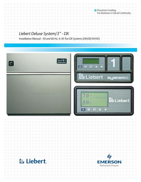
Liebert Deluxe System/3™ - DX
Liebert Deluxe System/3™ - DX

You also want an ePaper? Increase the reach of your titles
YUMPU automatically turns print PDFs into web optimized ePapers that Google loves.
Precision CoolingFor Business-Critical Continuity<strong>Liebert</strong> <strong>Deluxe</strong> <strong>System</strong>/3 - <strong>DX</strong>Installation Manual - 50 and 60 Hz, 6-30 Ton <strong>DX</strong> <strong>System</strong>s (DH/DE/VH/VE)
4.1 Drycooler Location . . . . . . . . . . . . . . . . . . . . . . . . . . . . . . . . . . . . . . . . . . . . . . . . . . . . . . . . . . 364.1.1 Outdoor Prop Fan Models . . . . . . . . . . . . . . . . . . . . . . . . . . . . . . . . . . . . . . . . . . . . . . . . . . . . . 364.1.2 Indoor Piggyback Models . . . . . . . . . . . . . . . . . . . . . . . . . . . . . . . . . . . . . . . . . . . . . . . . . . . . . . 364.2 Drycooler Installation . . . . . . . . . . . . . . . . . . . . . . . . . . . . . . . . . . . . . . . . . . . . . . . . . . . . . . . 364.3 Electrical Connections . . . . . . . . . . . . . . . . . . . . . . . . . . . . . . . . . . . . . . . . . . . . . . . . . . . . . . . 364.3.1 High Voltage . . . . . . . . . . . . . . . . . . . . . . . . . . . . . . . . . . . . . . . . . . . . . . . . . . . . . . . . . . . . . . . . 364.3.2 Low Voltage . . . . . . . . . . . . . . . . . . . . . . . . . . . . . . . . . . . . . . . . . . . . . . . . . . . . . . . . . . . . . . . . 364.3.3 Pump And Drycooler . . . . . . . . . . . . . . . . . . . . . . . . . . . . . . . . . . . . . . . . . . . . . . . . . . . . . . . . . 364.4 Glycol Piping. . . . . . . . . . . . . . . . . . . . . . . . . . . . . . . . . . . . . . . . . . . . . . . . . . . . . . . . . . . . . . . 364.5 Preparation of Glycol Solutions . . . . . . . . . . . . . . . . . . . . . . . . . . . . . . . . . . . . . . . . . . . . . . . . 455.0 WATER COOLED MODELS. . . . . . . . . . . . . . . . . . . . . . . . . . . . . . . . . . . . . . . . . . . . . . . . .485.1 Piping Considerations . . . . . . . . . . . . . . . . . . . . . . . . . . . . . . . . . . . . . . . . . . . . . . . . . . . . . . . 485.2 Condenser . . . . . . . . . . . . . . . . . . . . . . . . . . . . . . . . . . . . . . . . . . . . . . . . . . . . . . . . . . . . . . . . . 485.3 Water Regulating Valve. . . . . . . . . . . . . . . . . . . . . . . . . . . . . . . . . . . . . . . . . . . . . . . . . . . . . . 485.3.1 Testing Valve Function . . . . . . . . . . . . . . . . . . . . . . . . . . . . . . . . . . . . . . . . . . . . . . . . . . . . . . . 485.3.2 Manual Flushing . . . . . . . . . . . . . . . . . . . . . . . . . . . . . . . . . . . . . . . . . . . . . . . . . . . . . . . . . . . . 48ii
FIGURESFigure 1 Downflow (DH and DE models) cabinet and floor planning dimensional data . . . . . . . . . . . . . . . . 4Figure 2 Upflow 6, 8 and 10 ton (VH and VE models) cabinet and floor planning dimensional data . . . . . 6Figure 3 Upflow 6, 8 and 10 ton (VH and VE models) blower duct and deck dimensional data. . . . . . . . . . 7Figure 4 Upflow 15, 20 and 22 ton (VH and VE models) cabinet and floor planning dimensional data . . . 8Figure 5 Upflow 15, 20 and 22 ton (VH and VE models) blower duct and deck dimensional data. . . . . . . . 9Figure 6 Upflow 30 ton (VH and VE models) cabinet and floor planning dimensional data. . . . . . . . . . . . 10Figure 7 Upflow 30 ton (VH and VE models) blower duct and deck dimensional data . . . . . . . . . . . . . . . . 11Figure 8 Electrical connection details. . . . . . . . . . . . . . . . . . . . . . . . . . . . . . . . . . . . . . . . . . . . . . . . . . . . . . . 13Figure 9 Electrical field connections . . . . . . . . . . . . . . . . . . . . . . . . . . . . . . . . . . . . . . . . . . . . . . . . . . . . . . . 14Figure 10 Ducting configurations . . . . . . . . . . . . . . . . . . . . . . . . . . . . . . . . . . . . . . . . . . . . . . . . . . . . . . . . . . . 16Figure 11 Plenum dimensional data for 6 - 22 ton models . . . . . . . . . . . . . . . . . . . . . . . . . . . . . . . . . . . . . . . 17Figure 12 Plenum dimensional data for 30 ton models . . . . . . . . . . . . . . . . . . . . . . . . . . . . . . . . . . . . . . . . . . 18Figure 13 Piping: Fan speed control condensers . . . . . . . . . . . . . . . . . . . . . . . . . . . . . . . . . . . . . . . . . . . . . . . 21Figure 14 Piping: Lee-Temp control condensers . . . . . . . . . . . . . . . . . . . . . . . . . . . . . . . . . . . . . . . . . . . . . . . 22Figure 15 Downflow air cooled (DH) piping connections . . . . . . . . . . . . . . . . . . . . . . . . . . . . . . . . . . . . . . . . . 23Figure 16 Upflow air cooled (VH) piping connections . . . . . . . . . . . . . . . . . . . . . . . . . . . . . . . . . . . . . . . . . . . 24Figure 17 Outdoor air cooled 1-4 fan condenser cabinet and anchor dimensional data . . . . . . . . . . . . . . . . 25Figure 18 Outdoor air cooled 6 and 8 fan condenser cabinet and anchor dimensional data . . . . . . . . . . . . . 27Figure 19 Air cooled model general arrangement diagram . . . . . . . . . . . . . . . . . . . . . . . . . . . . . . . . . . . . . . . 28Figure 20 Piggyback condenser cabinet and floor planning dimensional data . . . . . . . . . . . . . . . . . . . . . . . 29Figure 21 Piggyback condenser piping connections . . . . . . . . . . . . . . . . . . . . . . . . . . . . . . . . . . . . . . . . . . . . . 30Figure 22 Lee-Temp control condenser. . . . . . . . . . . . . . . . . . . . . . . . . . . . . . . . . . . . . . . . . . . . . . . . . . . . . . . 34Figure 23 Lee-Temp control typical general arrangement diagram . . . . . . . . . . . . . . . . . . . . . . . . . . . . . . . . 35Figure 24 Downflow glycol cooled (DH) piping connections . . . . . . . . . . . . . . . . . . . . . . . . . . . . . . . . . . . . . . 38Figure 25 Upflow glycol cooled (VH) piping connections . . . . . . . . . . . . . . . . . . . . . . . . . . . . . . . . . . . . . . . . . 39Figure 26 Downflow GLYCOOL cooled (DE) piping connections . . . . . . . . . . . . . . . . . . . . . . . . . . . . . . . . . 40Figure 27 Upflow GLYCOOL cooled (VE) piping connections . . . . . . . . . . . . . . . . . . . . . . . . . . . . . . . . . . . 41Figure 28 1-4 fan drycooler cabinet and anchor dimensional data . . . . . . . . . . . . . . . . . . . . . . . . . . . . . . . . . 42Figure 29 6- and 8-fan drycooler cabinet and anchor dimensional data. . . . . . . . . . . . . . . . . . . . . . . . . . . . . 44Figure 30 Glycol general arrangement . . . . . . . . . . . . . . . . . . . . . . . . . . . . . . . . . . . . . . . . . . . . . . . . . . . . . . . 46Figure 31 GLYCOOL general arrangement . . . . . . . . . . . . . . . . . . . . . . . . . . . . . . . . . . . . . . . . . . . . . . . . . 47Figure 32 Water cooled general arrangement . . . . . . . . . . . . . . . . . . . . . . . . . . . . . . . . . . . . . . . . . . . . . . . . . 49Figure 33 Downflow water cooled (DH) piping connections . . . . . . . . . . . . . . . . . . . . . . . . . . . . . . . . . . . . . . 50Figure 34 Upflow water cooled (VH) piping connections . . . . . . . . . . . . . . . . . . . . . . . . . . . . . . . . . . . . . . . . . 51iii
PRODUCT MODEL INFORMATIONTable iVH = Upflow <strong>DX</strong>Model number designationDH 245 A – A A E IDH = Downflow <strong>DX</strong>DE = Downflow <strong>DX</strong>w/ Econ-O-CoilVE = Upflow <strong>DX</strong>w/ Econ-O-CoilNominal A =Capacity inThousandBTU/HAir U = 4 Step <strong>DX</strong> A = 460/3/60CooledB = 575/3/60W = Water H = <strong>DX</strong> withCooled Hot gasBypassG =GlycolCooledC = 208/3/60D = 230/3/60F = 380/3/50G = 415/3/50H = 230/3/50J = 200/3/50M = 380/415/3/50A = Advanced 0 = NoMicro-processor ReheatG = Advanced E = ElectricGraphicsReheatMicro-processorH = Hot WaterReheatG = Hot GasReheatT = SteamReheat0 = NoHumidifierEquipment InspectionUpon arrival of the unit, inspect all items for either visible or concealed damage. Damage should beimmediately reported to the carrier and a damage claim filed with a copy sent to <strong>Liebert</strong> or to yoursales representative.I =InfraredHumidifierG = Steam GridHumidifierS = SteamGeneratingHumidifier!WARNINGInstallation and service of this equipment should be done only by qualified personnel whohave been specially trained in the installation of air conditioning equipment. Improperinstallation could result in property damage, injury or loss of life.!WARNINGHazardous voltage! Always disconnect power before servicing.!CAUTIONEvaporator unit requires drain connections and may also require water supply. Do not locatedirectly above any equipment that could sustain water damage.v
Table iiUnit weightsAir Cooled ModelsDH/VH, 60 (50) HzWater Cooled ModelsDH/VH, 60 (50) HzGlycol Cooled ModelsDH/VH, 60 (50) HzGLYCOOL ModelsDE/VE, 60 (50) HzCapacity and Cooling Type Weight lbs (kg)75A 1205 (547)114A (115A) 1425 (647)125A (130A) 1440 (645)199A 1840 (835)245A 1960 (890)290A 2025 (920)380A 2160 (981)86W 1455 (661)127W (128W) 1675 (761)138W (143W) 1690 (768)219W 2110 (957)267W 2280 (1036)315W 2345 (1065)412W 2500 (1135)72G 1455 (661)110G (111G) 1685 (765)116G (121G 1700 (772)192G 2130 (967)240G 2300 (1045)265G 2365 (1074)363G 2530 (1148)72G 1615 (733)110G (111G) 1845 (837)116G (121G) 1860 (844)192G 2385 (1082)240G 2555 (1159)363G 2750 (1248)vi
Introduction1.0 INTRODUCTION1.1 <strong>System</strong> Descriptions<strong>Deluxe</strong> <strong>System</strong>/3 environmental control systems are available in several configurations. Each configurationcan operate with either Advanced Microprocessor Controls (AM), or Advanced MicroprocessorControls with Graphics (AG). A brief description of each, including operational differences, can befound below. Check model numbers to see what is supplied with your unit.1.1.1 Compressorized Two-Step <strong>System</strong>sThese systems may be air, water, or glycol cooled, depending on the heat rejection method selected.CoolingTwo stages of mechanical refrigeration are available.HeatingThree stages of electric reheat are standard; steam/hot water, hot gas (on water and glycol cooled systems)are optional.HumidificationInfrared is standard. Steam grid and steam generating humidification are optional.DehumidificationThese systems utilize the lag compressor.1.1.2 Compressorized Four-Step <strong>System</strong>sThe four-stage systems have all the features of a compressorized, two-stage system plus cylinderunloaders on one head of each compressor. This permits the compressors to operate at a reduced leveland increases energy efficiency during low-load conditions. The system responds to an increasingroom load with either a two-step or a four-step process of increasing the unit's cooling.CoolingThese systems have four stages of mechanical refrigeration:a. Lead compressor at reduced capacityb. Lead and lag compressors at reduced capacityc. Lead compressor at full capacity; lag compressor at reduced capacityd. Lead and lag compressors at full capacityHeatingThree stages of electric reheat are standard; hot water/steam are optional.HumidificationInfrared is standard; steam grid and steam generating humidification are optional.Dehumidification.These systems utilize the lag compressor.1
1.1.3 GLYCOOL (Chilled Glycol Cooling) <strong>System</strong>sIntroductionGLYCOOL systems have all of the features of a compressorized water or glycol system, plus a secondcooling coil that is connected into the water circuit. When fluid temperature is sufficiently low (belowroom temperature), cooling is provided by circulating the fluid through the second cooling coil (flow iscontrolled by a motorized valve.) This is then the primary cooling source, and it greatly reduces thecompressor operation.CoolingAt lower fluid temperatures, the second cooling coil acts as the main cooling system. The motorizedvalve opens proportionally to match the room load. At higher fluid temperatures, two or four stages ofmechanical refrigeration control the room load.HeatingThree stages of electric reheat are standard.HumidificationInfrared is standard; steam generating is optionalDehumidificationThese systems utilize the lag compressor.1.1.4 Dual Source Cooling <strong>System</strong>sThis system has all the features of a compressorized system but adds a second cooling coil that is connectedto a source of chilled water. This second coil is controlled by a modulating control valve. It isthe primary source of cooling and dehumidification so compressor operation is reduced.CoolingThe second coil acts as the primary cooling system. A modulating valve opens proportionally inresponse to the room load. Two and four stages of mechanical refrigeration as a secondary cooling systemat higher room loads.HeatingThree stages of electric reheat are standard.HumidificationInfrared is standard; steam generating is optionalDehumidificationThese systems utilize the chilled water valve, then the lag compressor if required by the load.2
Installation2.0 INSTALLATION2.1 Room PreparationThe room should be well-insulated and must have a sealed vapor barrier. The vapor barrier in theceiling can be a polyethylene film type. Use a rubber-base or plastic-base paint on concrete walls andfloors. Doors should not be undercut or have grilles in them.Outside, or fresh, air should be kept to an absolute minimum. Outside air adds to the heating, cooling,humidifying and dehumidifying loads of the site. It is recommended that outside air be kept below 5%of the total air circulated in the room.2.2 Location ConsiderationsFor a downflow unit, the unit can sit on an accessible, elevated flooring system. It may be necessary tofurnish additional pedestal support below the unit to ensure maximum structural support. A separatefloor stand for the unit may be used as support, independent of the elevated floor and installed priorto the flooring system.For downflow and upflow units, provide approximately 34" (864mm) service clearance on the left,right and in front of the unit whenever possible. The minimum space required for installation is 18"(45.7 cm) on the left end, 18" (45.7 cm) on the right end, and 24" (61 cm) in front of the unit. This spaceis necessary to permit routine maintenance, such as replacing filters, adjusting the fan speed andcleaning the humidifier.NOTEIf high efficiency 6" filters are used, 25" (63.5 cm) is required on the right end for removaland replacement of filters.Avoid locating units in an alcove or at the extreme end of a room that has a high aspect ratio (longnarrow room). Also avoid locating units too close together. This tends to reduce the effectiveness ofthe air distribution as compared to units located 30-40 feet (9-12m) apart.3
Installation2.3 Unit DimensionsFigure 1Downflow (DH and DE models) cabinet and floor planning dimensional dataSHADED AREASINDICATE A RECOMMENDEDCLEARANCE OF 34 (864mm)FOR COMPONENT ACCESS AND FILTERREMOVAL. FOR RECOMMENDEDMINIMUM CLEARANCE, REFERTO THE INSTALLATION MANUAL.UNIT DIMENSIONAL DATAUNITS WITHHIGH PRESSURE VALVE&FLOOR CUTOUT DIMENSIONSDPN000526 Rev04
InstallationTable 1Air CooledWater CooledGlycol CooledGLYCOOLDownflow (DH and DE models) dimensionsDimensional Datainches (mm)60 Hz 50 Hz A B C D E F G H J K LDH75ADH86WDH72GDE72GDH114ADH127WDH110GDE110GDH125ADH138WDH116GDE116GDH199ADH219WDH192GDE192GDH245ADH267WDH240GDE240GDH290ADH315WDH265GDH380ADH412WDH363GDE363GDH75ADH86WDH72GDE72GDH115ADH128WDH111GDE111GDH130HDH143WDH121GDE121GDH199ADH219WDH192GDE192GDH245ADH267WDH240GDE240GDH290ADH315WDH265GDH380ADH412WDH363GDE363G74(1880)74(1880)74(1880)99(2515)99(2515)99(2515)122(3098)70(1778)70(1778)70(1778)95(2413)95(2413)99(2515)118(2997)35(889)35(889)35(889)35(889)35(889)35(889)35(889)32(813)32(813)32(813)32(813)32(813)32(813)32(813)72(1829)72(1829)72(1829)97(2464)97(2464)97(2464)120(3048)33(838)33(838)33(838)33(838)33(838)33(838)33(838)14-1/4(362)14-1/4(362)14-1/4(362)16-1/4(413)16-1/4(413)16-1/4(413)16-1/4(413)54-3/4(1391)54-3/4(1391)54-3/4(1391)77-3/4(1975)77-3/4(1975)77-3/4(1975)100-3/4(2559)35-5/8(905)35-5/8(905)35-5/8(905)35-5/8(905)35-5/8(905)35-5/8(905)35-5/8(905)63-1/2161363-1/2161363-1/2161388-1/2(2248)88-1/2(2248)27(686)27(686)27(686)27(686)27(686)-- --111-1/2(2832)27(686)5
InstallationFigure 2Upflow 6, 8 and 10 ton (VH and VE models) cabinet and floor planning dimensional dataProjection ofDisplay Bezel5/8" (16mm)2" (51mm)35" overall(889mm)32"(838mm)PlenumFlangeUNIT DIMENSIONAL DATA74" overall(1880mm)70" (1778mm)Plenum Flange72"(1829mm)2"(51mm)DUCT CONNECTION DATAModels With Rear ReturnAir grillesupplied onunits withfront returnair onlyShaded areas indicatea recommendedclearance of 34"(864mm) for componentaccess and filterremoval72" base(1829mm)33" Base(838mm)1" (25.4mm)Flange provided onblower outlet forsupply air ducting1" (25.4mm) flangefor decorativeplenum alignmentFLOOR CUTOUT DIMENSIONSModels With Bottom Return20-1/4"(514mm)33"(838mm)22"(559mm)69-3/4"(1172mm)4-1/2"(114mm)Air returnopening4"(102mm)11"(279mm)2-1/8"(54mm)69-3/4"(1172mm)Air returnopening72"(1829mm)Floor Level1-1/8"(29mm)DPN000527 Rev06
InstallationFigure 3Upflow 6, 8 and 10 ton (VH and VE models) blower duct and deck dimensional data74" ref(1880mm)Duct Flange on BlowerABBlower DeckTop of UnitFDC35" ref(889mm)72" ref(1829mm)Front of UnitBlower Duct Flange LocationFront or Rear Air SupplyDPN000528 Rev0Table 2VH075AVH086WVH072GVE072GVH115A/VH114AVH128W/VH127WVH111G/VH110GVE111G/VE110GVH130A/VH125AVH143W/VH138WVH121G/VH116GVE121G/VE116GUpflow 6, 8 and 10 ton (VH and VE models) blower duct and deck dimensional dataBlower15 x 1515 x 1112 x 915 x 1515 x 1115 x 1515 x 11SupplyMotorHPTOP FRONT 1-5TOP REAR 1-5TOP FRONT 1-5TOP REAR 1-5TOP FRONT 1-5TOP REAR 1-5TOP FRONT 1.5-5TOP REAR 1.5-5TOP FRONT 2-7.5TOP REAR2-57.5TOP FRONT 2-5TOP REAR 2-5TOP FRONT 3-10TOP REAR3-57.5-10Dimensional Data inches (mm)A B C D F22-7/8(581)22-7/8(581)22-7/8(581)22-7/8(581)22-7/8(581)22-7/8(581)22-7/8(581)22-7/8(581)22-7/8(581)22-7/8(581)22-7/8(581)22-7/8(581)22-7/8(581)3-1/2(89)12-5/16(313)3-1/2(89)12-5/16(313)5-7/8(149)12-5/16(313)3-1/2(89)12-5/16(313)3-1/2(89)12-5/16(313)3-1/2(89)12-5/16(313)3-1/2(89)22-7/8(581) 12-5/1623 7/8 (313)(606)18-13/16(478)18-13/16(478)14-7/8(378)14-7/8(378)12-7/16(316)12-7/16(316)18-13/16(478)18-13/16(478)14-7/8(378)14-7/8(378)18-13/16(478)18-13/16(478)14-7/8(378)14-7/8(378)16-3/16(411)16-3/16(411)16-3/16(411)16-3/16(411)13 3/4(349)13 3/4(349)16-3/16(411)16-3/16(411)16-3/16(411)16-3/16(411)16-3/16(411)16-3/16(411)16-3/16(411)16-3/16(411)1-1/2(38)1-1/2(38)1-1/2(38)1-1/2(38)1-1/2(38)1-1/2(38)1-1/2(38)1-1/2(38)1-1/2(38)1-1/2(38)4 1/2(114)1-1/2(38)1-1/2(38)1-1/2(38)1-1/2(38)4 1/2(114)7
InstallationFigure 4 Upflow 15, 20 and 22 ton (VH and VE models) cabinet and floor planning dimensional dataProjection ofDisplay Bezel 35" overall5/8" (16mm) (889mm)UNIT DIMENSIONAL DATA2"(51mm)32"(838mm)PlenumFlange99" overall(2515mm)95"(2413mm)Plenum Flange76"(1930mm)2"(51mm)DUCT CONNECTION DATAModels With Rear ReturnAir grillesupplied onunits withfront returnair onlyShaded areasindicate arecommendedclearance of 34"(864mm) forcomponentaccess and filterremoval97" Base(2464mm)33" Base(838mm)1"(25.4mm)Flanges provided onblower outlets forsupply air ducting1" (25.4mm) flangefor decorativeplenum alignment33"(838mm)5-1/2"(140mm)FLOOR CUTOUT DIMENSIONSModels With Bottom Return24-1/4"(616mm)22"(559mm)Air returnopening94-3/4"(2407mm)Airreturnopening94-3/4"(2407mm)97"(2464mm)4"(102mm)11"(279mm)2-1/8"(54mm)Floor Level1-1/8"(29mm)DPN000529 Rev08
InstallationFigure 5Upflow 15, 20 and 22 ton (VH and VE models) blower duct and deck dimensional data99" (2514.6) ref.Duct Flanges on Two BlowerABBlower DeckTOP OF UNITFDCEC35"(889mm)ref.76"(1930.4mm)ref.FRONT OF UNITBlower Duct Flange LocationFront or Rear Air SupplyDPN000530 Rev0Table 3Upflow 15, 20 and 22 ton (VH and VE models) blower duct and deck dimensional dataBlowerSupplyMotorHPDimensional Data inches (mm)A B C D E FTOPFRONT3-7.5 20-3/8 (518) 3-1/210 22-7/8 (581) (89)18-13/16(478)16-3/16(411)12-11/16(322)1-1/2 (38)15 x 15TOPREAR3-5 20-3/8 (518)7.5-10 25-3/8 (645)12-5/16(313)18-13/16(478)16-3/16(411)12-11/16(322)10(254)1-1/2 (38)4-1/2 (114)VH199AVH219WVH192GVE192G15 x 11TOPFRONTTOPREAR5-7.5 20-3/8 (518)10 22-7/8 (581)15 25-3/8 (645)5 20-3/8 (518)7.5-15 25-3/8 (645)3-1/2(89)12-5/16(313)14-7/8(378)14-7/8(378)16-3/16(411)16-3/16(411)16-5/8(422)14-1/2(368)16 5/8(422)14 1/2(368)1-1/2 (38)1-1/2 (38)4-1/2 (114)12 x 9TOPFRONT7.5 20-3/8 (518)10 22-7/8 (581)15 25-3/8 (645)5-7/8(149)12-7/16(316)13-3/4(349)22-3/4(578)18-5/8(473)1-1/2 (38)TOPREAR7.5-15 25-3/8 (645)12-5/16(313)12-7/16(316)13-3/4(349)18-5/8(473)4-1/2 (114)VH245AVH290AVH267WVH315WVH240GVH265GVE240G15 x 1515 x 11TOPFRONTTOP REARTOPFRONT5-7.5 20 3/8 (518) 3-1/210 22-7/8 (581) (89)18-13/16(478)16-3/16(411)12-11/16(322)1-1/2 (38)12-11/165 20 3/8 (518) 12-5/16 18-13/16 16-3/161-1/2 (38)(322)(313) (478) (411)7.5-10 25 3/8 (645) 10 (254) 4 1/2 (114)7.5 20 3/8 (518)16-5/810 22-7/8 (581) 3-1/2 14-7/8 16-3/16(422) 1-1/2 (38)15 25 3/8 (645) (89) (378) (411)14-1/220 27 7/8 (708) (368) 4 1/2 (114)TOPREAR7.5-15 25 3/8 (645) 12-5/1620 27 7/8 (708) (313)14-7/8(378)16-3/16(411)14-1/2(368)4-1/2(114)9
InstallationFigure 6Projection ofdisplay bezel5/8" (16mm)2"(51mm)Upflow 30 ton (VH and VE models) cabinet and floor planning dimensional data35"(889mm)Overall32"(838mm)PlenumFlangeUNIT DIMENSIONAL DATA122"(3099mm)Overall118"(2997mm)Plenum Flange2" (51mm)76"(1930mm)DUCT CONNECTION DATAModels With Rear ReturnAir grillesupplied onunits withfront returnair onlyShaded areas indicate arecommended clearanceof 34" (864mm) forcomponent access andfilter removal120"(3048mm)Base33"(838mm)Base1"(25.4mm)Flanges provided onblower outlets forsupply air ducting1" (25.4mm) flangefor decorativeplenum alignment33"(838mm)FLOOR CUTOUT DIMENSIONSModels With Bottom Return5-1/2"(140mm)24-1/4"(616mm)22"(559mm)Air ReturnOpening4"(102mm)113-1/2"(2883mm)Air ReturnOpening113-1/2"(2883mm)120"(3048mm)11"(279mm)4-1/4"(108mm)Floor Level3-1/4"(83mm)DPN00531 Rev010
InstallationFigure 7Upflow 30 ton (VH and VE models) blower duct and deck dimensional data122" (3098.8) ref.TOP OF UNITDuct Flanges on Three BlowerABBlower DeckFDC E G E CFRONT OF UNITBlower Duct Flange Location35"(889)ref.Front or Rear Air Supply76"(1930.4)refDPN000532 Rev0Table 4VH380AVH412WVH363GVE363GUpflow 15, 20 and 22 ton (VH and VE models) blower duct and deck dimensional dataBlower15 x 515 x11SupplyTOPFRONTTOPREARTOPFRONTTOPREARMotorHP101010-152010-20Dimensional Data inches (mm)A B C D E F G22-7/8(581)22-7/8(581)27-7/8(708)27-7/8(708)3-1/2(89)12-5/16(313)3-1/2(89)12-5/16(313)18-13/16(478)18-13/16(478)14-7/8(378)14-7/8(378)16-3/16(411)16-3/16(411)16-3/16(411)16-3/16(411)10(254)10(254)10(254)10(254)1-1/2(38)4-1/2(114)18-5/8(473)18 5/8(473)1-1/2(38) 14-11/164-1/2 (373)(114)4-1/2(114)14-11/16(373)11
2.4 PipingInstallationAll fluid and refrigeration connections to the unit, with the exceptions of the condensate drain andlive steam, are sweat copper. Factory-installed piping brackets must not be removed. Field-installedpiping must be installed in accordance with local codes and must be properly assembled, supported,isolated and insulated. Avoid piping runs through noise-sensitive areas, such as office walls and conferencerooms.Refer to specific text and detailed diagrams in this manual for other unit-specific piping requirements2.4.1 Drain LineA 3/4" NPT is provided for the evaporator coil condensate drain. This drain line also drains thehumidifier, if applicable. The drain line must be located so it will not be exposed to freezing temperatures.The drain should be at least the full size of the drain connection and pitched a minimum of 1/8"per ft. (11mm per meter).NOTEThis line may contain boiling water. Use copper or other suitable material for the drain line.For units without a condensate pumpThe unit is shipped from the factory with an internally-mounted trap. No external trap isrequired. The drain line must comply with all applicable codes.For units with a factory-installed condensate pump optionThe unit is shipped from the factory with a condensate pump installed. The condensate pumpdischarge (drain) line must comply with all applicable codes.For units with a field-installed condensate pumpThe unit is shipped from the factory with the condensate pump option, unmounted in the unit,which must be installed in the field. The unit has an internally mounted trap. The drain linefrom the unit to the condensate pump does not require a trap. The discharge (drain) line fromthe pump must comply with all applicable codes.2.4.2 Piping Considerations for Raised-Floor ApplicationsAll piping below the elevated floor must be located so that it offers the least resistance to air flow.Careful planning of the piping layout under the raised floor is required to prevent the air flow frombeing blocked. When installing piping on the subfloor, it is recommended that the pipes be mounted ina horizontal plane rather than stacked one above the other. Whenever possible, the pipes should berun parallel to the air flow.2.5 Electrical ConnectionsThree-phase electrical service is required for all models in either 208, 230, 460 or 575V, 60Hz; or 200,230 or 400V, 50 Hz. Electrical service shall conform to national and local electrical codes.Install a manual electrical disconnect switch within 5 feet (1.6 m) of the unit in accordance withcodes. A factory-supplied disconnect switch may be factory-mounted within the unit and accessiblefrom the exterior.12
InstallationFigure 8Electrical connection detailsROOM UNIT CONNECTIONSNOTES3-phase line voltagesupply to line voltageconnection block oroptional main disconnectswitch (Note 2)Earth ground to groundlug bolt or optionalground bar2-wire connection forremote unit shutdown(Note 3)2-wire connection foreach Special Alarm(Note 4)2-wire connectionoptional SiteScan4-pin plug connections foroptional remotetemperature and humiditysensor2-wire connection forcommon alarm2-wire connection forheat rejection interlock(Note 5)OR37 38 24 50 51 55 56 77 7875 76 70 71L1L2L322 ga. 4-wire cable6-inchpigtails atjunctionboxTo line voltagecomponents on <strong>Liebert</strong>room unit electric panelTo line voltagecomponents in<strong>Liebert</strong> roomunitP16ControlBoardTerminals 75 & 76 areconnected to common alarmrelay (K3) NO contact (max 1Aat 24V)Wires 70 & 71 are connectedto compressor side switchesand Econ-O-Coil relay (R5).R5 is provided on FE/UEunits only.1. Refer to specification sheet forFull Load Amps and Wire SizingAmps.2. Field-supplied room unit maindisconnect switch in accordancewith local codes ordered asoptional equipment and factoryinstalledin <strong>Liebert</strong> room unit.3. For remote unit shutdown,replace jumper between 37 & 38 atterminal strip with NormallyClosed switch having a minimum75VA rating.4. Special alarm connection made byadding Normally Open contactsbetween Terminals 24 & 50, 24 &51, 24 & 55 and 24 & 56. Only onealarm (between 24 & 50) isavailable on standardmicroprocessor.5. Heat rejection interlock is notsupplied on chilled water models.6. Field-supplied disconnect switchmounted within sight ofcondenser/drycooler and inaccordance with local codes orordered as optional equipmentand factory-installed in <strong>Liebert</strong>condenser/drycooler. CDF-065,CDF-083, CDF-086, CDF-097 andCDF-104L are single-phase fanspeed condensers. All othercondensers and all drycooler andpump packages require a 3-phaseline voltage supply.7. Glycol pump package suppliedwith drycoolers only. Pump 2 issupplied only when dual pumppackage is ordered.8. Lee-Temp tanks and assemblysupplied on air-cooledcondensers with Lee-Tempcontrol systems only.InterconnectedRemote Heat Rejection Connections2-wire connection plusground for Lee-Temp heaterpads (Note 8)3- or single-phase line voltagesupply to optional maindisconnect switch (Note 6)Earth Ground2-wire connection for heatrejection interlock3-wire line voltageconnection plus ground forglycol pump. An additional3-wire line voltage neededfor dual pump packages(Note 7).Electric Panel1See Note 821 fan2 fan3 fanDiagram is for directdrive air-cooledcondensers(for air-cooled units)and direct drivedrycoolers(for glycol/GLYCOOLunits).Wire LegendFactory-supplied linevoltage wiringField-supplied linevoltage wiringFactory-supplied 24V,NEC Class 2 wiringField-supplied 24VNEC Class 2 wiringField-supplied earthgrounding wire13
InstallationFigure 9Electrical field connectionsField-supplied disconnect switch when factory-installedunit disconnect switch is not providedFactory-installed unitdisconnect switch (optional)Monitoring panel3-phaseelectricservicenot by<strong>Liebert</strong>3-phase connection; electricservice connection terminalswhen factory disconnect switchis suppliedFactory-installed disconnectswitch (optional)Smoke detector alarmconnections; field-supplied 24V;Class 2 wire to remote alarmcircuits; factory-wired contactsfrom optional smoke detector are#91-comm., #92-NO and #93-NCCommon alarm connection;field-supplied 24V; Class 2 wireto common alarm from pigtails75 +76, which arefactory-connected to commonalarm relay (R3)Electric handy boxfactory-installedwith coverHeat rejection connection;field-supplied 24V; Class 1 wiringto interlock heat rejection frompigtails 70 and 71, which arefactory-connected to compressorside switchesCondensate pump connection forpumps shipped loose; factory-suppliedwiring from pump to pigtails; fuses areinstalled on electric panelRemote unit shutdown; replace existingjumper between Terminals 37 and 38 witha normally closed switch having aminimum 50VA rating; use field-suppliedClass 1 wireField-wired to componentson electric panelElectric connection block3-phase connection; electric serviceconnection terminals when factorydisconnect switch is not suppliedEarth ground connection (60Hz);connection terminal for field-suppliedearth grounding wireEarth ground bar (50Hz only); connectionterminals with factory-ground from eachhigh-voltage component for field-suppliedearth grounding wire3-phase electric service not by <strong>Liebert</strong>Special alarm connections; field-supplied 24V, Class 1wire for special alarms; connections made by addingnormally open contact between terminals (24 & 50) forstandard microprocessor; advanced microprocessorhas four alarms at terminal: 24 & 50; 24 & 51; 24 & 55and 24 & 56Analog inputs; optional terminals 41 to 48 provideconnections for shielded, twisted-pair cable to asmany as four customer supplied analog sensors(AM and AG only)Site monitoring connection; terminals 77(-) and 78(+)are for connection of a 2-wire, twisted-paircommunication cable (available from <strong>Liebert</strong> orothers) to optional SiteScan and arefactory-connected to the interface board on the unitElectric conduit knockouts on bottom andrear of wire raceway; knockout sizes are1-3/8" (34.9mm) or 1-3/4" (44.5mm) or2-1/2" (63.5mm)DPN000538 Rev1NOTERefer to specification sheet for full load amp and wire size amp ratings.14
Installation2.6 Air Distribution Considerations2.6.1 Raised-Floor Air Flow Distribution ConsiderationsTo ensure proper air distribution, any unusual restrictions within the air circuit must be avoided. Forunder-floor air distribution, observe the following guidelines:Select the air supply grilles and perforated panels for the raised floor to ensure minimum loss of pressurein the circuit. Air volume dampers on grilles, which extend several inches below the surface ofthe raised floor, are usually detrimental to airflow. Consideration of the height of the damper on thegrille in conjunction with the floor height will determine whether this type of grille may be used.The grilles used in raised floors vary in size, the largest being approximately 18" x 6" (457 x 152 mm).A larger grille size would be detrimental to the structural capacity of the raised floor panel. An18" x 6" (457 x 152mm) heavy-duty pencil-proof type grille typically has 56 square inches (0.036m 2 ) offree area. Perforated panels are available from various manufacturers of raised floors. These panelsare usually 2' x 2' (610 x 610mm) square and have a nominal free area of approximately 108 to 144square inches (0.07 to 0.09 m 2 ). Use caution in selecting perforated panels as some manufacturershave only 36 to 40 square inches (0.023 to 0.026 m 2 ) of free area, requiring four times as many panels.Avoid floor elevations below 7-1/2" (190.5mm), loosely installed flooring systems, and below-floorobstructions such as: electrical wiring chases, unusually long computer system cables, or piping clusters.All piping below the elevated floor must be located so that it offers the least resistance to air flow.Careful planning of the piping layout under the raised floor is required to prevent the air flow frombeing blocked. When installing piping on the subfloor, it is recommended that the pipes be mounted ina horizontal plane rather than stacked one above the other. Whenever possible, the pipes should berun parallel to the air flow.Always check specifications of the floor supplier before specifying the total number of perforated panelsand grilles required to handle the air flow. The proper specifications for grilles and perforated panelsshould indicate the total free area required for air delivery rather than the number of panels andgrilles. (See Table 5 below for recommended free area required for each model.) This table indicatesthe recommended free area based on having the supply air grilles and perforated panels sized to handleapproximately 75% of the total cubic feet per minute (CFM) of the units at a velocity of 550 to 600ft./min. (2.8 - 3.1 m/s). The remaining 25 percent of the air flow in the raised floor passes throughcable cutouts, cracks between the panels and other leakage areas.Table 5DirectExpansionUnitsRecommended free area ft 2 (m 2 for grilles or perforated panels at output velocities of550 and 600 fpm (2.8 and 3.1 m/s)Model DH/DE or FH60 (50) Hz2.6.2 Upflow <strong>System</strong>s Additional Installation Considerations550 fpm(2.8 m/s)600 fpm(3.1 m/s)75A 86W 72G 4.6 (0.41) 4.2 (0.38)114A (115A) 122W (128W) 110G (111G) 6.3 (0.57) 5.8 (0.52)125A (130A) 138W (143W) 116G (121G) 7.7 (0.69) 7.1 (0.64)199A 219W 192G 11.5 (1.04) 10.5 (0.95)245A 267W 240G 13.9 (1.25) 12.8 (1.15)290A 315W 265G 16.4 (1.48) 15.0 (1.35)380A 412W 363G 20.4 (1.84) 18.8 (1.70)Upflow models can be configured in several different ways with front return, rear return, or bottomreturn and top front supply or top rear supply (on <strong>DX</strong> models). For in-room applications with no ductwork,and optional plenum with grill, proper clearance must be maintained on the return air side ofthe unit. For a front return, this means several feet in front of the unit. For a bottom return, at least6-8 inches of unrestricted under-floor height is needed.15
Installation2.6.3 Ducted Application InstallationDuct flanges are supplied on the blower outlets. Follow the SWACNA-Duct Construction Standard forsingle-, dual-, or triple-blower systems. Do not run ductwork off the perimeter flange on the top of theunit. This flange is for positioning and attaching the optional air discharge plenum with grill. Attachinga duct to this flange may reduce airflow to inadequate levels.Figure 10 Ducting configurations2122112.6.4 Plenum InstallationWhen installing the plenum to the top of system, secure the plenum to the unit flange using sheetmetal screws.2.6.5 Filter Box Installation1. Straight section of duct off of unit to be 1.5 to 2.5 times thelongest blower dimension.2. Typical ducting shown; may run to either side.* Follow standard practices on all duct work.DPN000533 Rev0When installing the filter box to the back of the unit, secure the box to the unit using self tappingsheet metal screws. Seal around all edges with a silicone sealant to prevent air leakage.16
InstallationFigure 11 Plenum dimensional data for 6 - 22 ton models2"(50mm)HCD1"(25mm)J18"(457mm)NOTE: FLANGES PROVIDEDON BLOWER(S) OUTLETFOR SUPPLY AIR DUCTINGWHEN SOLID PANELPLENUM IS USED.1"(25mm)1"(25mm)BFAE1"(25mm)BOTH TOP DUCT OPENINGS ANDFRONT GRILLE ARE SHOWN.SEE SPECIFICATION SHEETFOR SPECIFIC APPLICATION.2"(50mm)CD2"(50mm)1"(25mm)FLANGE IS STANDARD ON ALL UNITSEXCEPT DOWNFLOW (DH/DE)MODELS WHERE IT MUST BESPECIFIED IF REQUIRED.DPN000620 Rev0Table 6Plenum dimensional data for 6 - 22 ton models, in. (mm)Model A B C D E FDH/DE/VH/VE-75A, 86W, 72GDH/DE/VH/VE-115A, 128W, 111GDH/DE/VH/VE-114A, 127W, 110GDH/DE/VH/VE-130A, 143W, 121GDH/DE/VH/VE-125A, 138W, 116GDH/DE/VH/VE-199A, 219W, 192GDH/DE/VH/VE-245A, 267W, 240GDH/VH/-290A, 315W, 265G74(1880)99(2515)34(864)34(864)70(1778)95(2413)32(813)32(813)60(1524)70(1778)7(178)14-1/2(368)Grille Free AreaSq Ft (sq m)5.85(.54)6.83(.63)Plenum Height In. (mm)HJ20 (508) 1 (25)22-3/4 (578) 2-3/8 (60)34-3/4 (883) 2-3/8 (60)17
InstallationFigure 12 Plenum dimensional data for 30 ton modelsNote: Flanges providedon blower outlet(s) forsupply air ducting whensolid panel plenum is usedCD1" (25mm)LK1"(25mm)18" (457mm)BFEGAEHJBoth top duct openings andfront grilles are shown. Seespecification sheet for specificapplication2"(50.8mm)1"(25mm)CD1"(25mm)2"(50mm)Flange is standard on allunits except downflow (DH/DE)models where is must be specifiedif requiredDPN000621 Rev0Table 7Plenum dimensional data for 30 ton models in. (mm)Model A B C D E F G H J K LDH/DE/VH/VE-380A,412W, 363G122(3099)34(864)118(2997)32(813)44(1118)3-1/2(89)4(102)7(178)16(406)20508)1(25)GrilleFree AreaSq Ft (sq m)10.14(.94)18
Air Cooled Models3.0 AIR COOLED MODELS3.1 Condenser Location3.1.1 Outdoor Prop Fan ModelsThe air cooled condenser should be located for maximum security and maintenance accessibility.Avoid ground level sites with public access or areas that contribute to heavy snow or ice accumulations.Utilize centrifugal condensers whenever interior building locations must be used. To assureadequate air supply, <strong>Liebert</strong> recommends that condensers be located in a clean air area, away fromloose dirt and foreign matter that may clog the coil. Condensers should not be located in the vicinity ofsteam, hot air or fume exhausts. Also, condensers should be located no closer than 3 feet (1 meter)from a wall, obstruction or adjacent unit.Install condensers in a level position to assure proper refrigerant flow and oil return. For roof installation,mount condensers on steel supports in accordance with local codes. To minimize sound andvibration transmission, mount steel supports across load bearing walls.For ground installation, a concrete pad will provide adequate support. Condenser legs have mountingholes for securing the condenser to steel supports or concrete pad.3.1.2 Indoor Piggyback ModelsThe piggyback condenser can be located directly behind the <strong>Deluxe</strong> unit or in a separate remoteindoor location. It may be placed directly against an outside wall, with the proper openings cut in thewall for entering and leaving air. If it cannot be located near a wall, the unit may be ducted to the outside.Proper grilles/screens are required on the outside wall.3.2 Electrical Connections3.2.1 High VoltageHigh voltage electrical service is required for all air cooled condensers at the location of the condenser.This power supply does not have to be the same voltage as the indoor unit. This separatepower source may be 208/230, 460 or 575V, 60Hz; or 200/230 or 380/415V, 50Hz. The disconnectswitch may be factory supplied and mounted in the electrical panel or field supplied and mounted perlocal and national codes.3.2.2 Low VoltageA control interlock between the condenser and the indoor unit is required and is connected between70 and 71 on the wire raceway in the compressor compartment of the indoor unit and the electricpanel of the air cooled condenser.3.2.3 Lee-Temp/Flood Back Head Pressure Control Condensers (Standard on PiggybackModels)Lee-Temp condensers require a separate power supply for the heated receivers. This power supply isconnected to the electrical connection box on the end of the receiver.19
3.3 Refrigerant PipingAir Cooled ModelsAll refrigeration piping should be installed with high temperature brazed joints. Prevailing goodrefrigeration practices should be employed for piping supports, leak testing, dehydration and chargingof the refrigeration circuits. The refrigeration piping should be isolated from the building by theuse of vibration isolating supports. Piping, including inverted trap(s), must be routed to allowunobstructed access to the panel per the NEC.Traps should be installed in the hot gas lines on vertical risers every 25 feet (7.6 meters) in elevation.These traps will collect condensed refrigerant and refrigerant oil during the off cycle of the unit andensure flow of refrigerant oil during operation. Hot gas vertical risers may require downsizing of theline to provide for adequate refrigerant velocities to move oil up the riser. This is especially true onsystems with unloaders.Contact your local <strong>Liebert</strong> representative for factory approval whenever a refrigerant piping runexceeds 200 feet (60 meters) equivalent length or when condensers must be located below the level ofthe cooling coil.Table 8 Recommended line sizes – O.D. copper75A 114A (115A) 125A (130A) 199A 245A 290A 380A50 ft(15m)100 ft.(30m)150 ft.(45m)Hot GasLineLiq.LineHot GasLineLiq.LineHot GasLineLiq.LineHot GasLineLiq.LineHot GasLineLiq.LineHot GasLineLiq.LineHot GasLine5/8 1/2 7/8* 1/2 7/8* 1/2 7/8 5/8 1-1/8* 7/8 1-1/8 7/8 1-3/8 7/87/8 1/2 7/8* 5/8 7/8 5/8 1-1/8* 7/8 1-1/8 7/8 1-1/8 7/8 1-3/8 7/87/8 5/8 7/8 5/8 7/8 5/8 1-1/8 7/8 1-1/8 7/8 1-1/8 7/8 1-3/8 1-1/8*With 4-Step Models, use one (1) trade size smaller (7/8 = 3/4, 1-1/8 = 7/8).Liq.Line20
Air Cooled ModelsFigure 13 Piping: Fan speed control condensersReturningliquid line (Typ.)Entering hotgas line (Typ.)10060Pg4Inverted traps are to be field-supplied and installed (Typ.).When installing traps, clearance must be provided forswing of end access door. Traps are to extend above baseof coil by a minimum of 7-1/2" (190mm).Table 9Condenser ModelNumberFan speed control condenser piping connection sizes - Cu ODEntering HotGas LineIn. (mm)ReturningLiquid LineIn. (mm)CDF-065 1/2 (12.7) 1/2 (12.7)CDF-083L 1/2 (12.7) 1/2 (12.7)CDF-086 7/8 (22.2) 1/2 (12.7)CDF-097/107C 7/8 (22.2) 1/2 (12.7)CDF-104L 7/8 (22.2) 1/2 (12.7)CDF-130 7/8 (22.2) 5/8 (15.9)CDF-165L 7/8 (22.2) 5/8 (15.9)CDF-175 7/8 (22.2) 5/8 (15.9)CDF-205L 1-1/8 (28.6) 7/8 (22.2)CDF-217C/216C 1-1/8 (28.6) 7/8 (22.2)CDF-251L 1-1/8 (28.6) 7/8 (22.2)CDF-258 1-1/8 (28.6) 7/8 (22.2)CDF-291 1-1/8 (28.6) 1-1/8 (28.6)CDF-308L 1-3/8 (34.9) 1-1/8 (28.6)CDF-330L 1-3/8 (34.9) 1-1/8 (28.6)CDF-360/349C 1-3/8 (34.9) 1-1/8 (28.6)CDF-415L 1-3/8 (34.9) 1-1/8 (28.6)CDF-480C 1-5/8 (41.3) 1-1/8 (28.6)CDF-510C 1-5/8 (41.3) 1-1/8 (28.6)For runs longer than 150 feet (45.7m) equivalent length, consultfactory for proper line sizing.21
Air Cooled ModelsFigure 14 Piping: Lee-Temp control condensersLee-Temp receiver tankEntering hot gas line (Typ.)Returning liquid line (Typ.)10061Pg6Table 10Lee-Temp control condenser piping connection sizesCondenser Connections-ODSinches (mm)Lee-Temp Connections-ODSinches (mm)Model # Hot Gas A Liquid BLee-TempSizeHot GasTee FLiq. to L-TValve CReceiverOut DCDL-065 1/2 (12.7) 1/2 (12.7) (2) W-4 1-1/8 (28.6) 7/8 (22.2) 5/8 (15.9)CDL-083L 1/2 (12.7) 1/2 (12.7) (2) W-4 1-1/8 (28.6) 7/8 (22.2) 5/8 (15.9)CDL-086 7/8 (22.2) 1/2 (12.7) (2) W-4 1-1/8 (28.6) 7/8 (22.2) 5/8 (15.9)CDL-097 7/8 (22.2) 1/2 (12.7) (2) W-4 1-1/8 (28.6) 7/8 (22.2) 5/8 (15.9)CDL-104L 7/8 (22.2) 1/2 (12.7) (2) W-4 1-1/8 (28.6) 7/8 (22.2) 5/8 (15.9)CDL-130 7/8 (22.2) 5/8 (15.9) (2) W-4 1-1/8 (28.6) 7/8 (22.2) 5/8 (15.9)CDL-165 7/8 (22.2) 5/8 (15.9) (2) W-4 1-1/8 (28.6) 7/8 (22.2) 5/8 (15.9)CDL-175 7/8 (22.2) 5/8 (15.9) (2) W-4 1-1/8 (28.6) 7/8 (22.2) 5/8 (15.9)CDL-205L 1-1/8 (28.6) 7/8 (22.2) (2) W-4 1-1/8 (28.6) 7/8 (22.2) 5/8 (15.9)CDL-217C 1-1/8 (28.6) 7/8 (22.2) (2) W-5 1-3/8 (34.9) 7/8 (22.2) 7/8 (22.2)CDL-251L 1-1/8 (28.6) 7/8 (22.2) (2) W-4 1-3/8 (34.9) 7/8 (22.2) 7/8 (22.2)CDL-258 1-1/8 (28.6) 7/8 (22.2) (2) W-5 1-3/8 (34.9) 7/8 (22.2) 7/8 (22.2)CDL-291 1-1/8 (28.6) 5/8 (15.9) (2) W-5 1-3/8 (34.9) 7/8 (22.2) 7/8 (22.2)CDL-308L 1-3/8 (34.9) 1-1/8 (28.6) (2) W-5 1-3/8 (34.9) 7/8 (22.2) 7/8 (22.2)CDL-330L 1-3/8 (34.9) 1-1/8 (28.6) (2) W-5 1-3/8 (34.9) 7/8 (22.2) 7/8 (22.2)CDL-360 1-3/8 (34.9) 1-1/8 (28.6) (2) W-5 1-3/8 (34.9) 7/8 (22.2) 7/8 (22.2)CDL-415L 1-3/8 (34.9) 1-1/8 (28.6) (2) W-5 1-3/8 (34.9) 7/8 (22.2) 7/8 (22.2)CDL-480C 1-5/8 (41.3) 1-1/8 (28.6) (2) W-6 1-3/8 (34.9) 1-1/8 (28.6) 7/8 (22.2)CDL-510C 1-5/8 (41.3) 1-1/8 (28.6) (2) W-41 1-3/8 (34.9) 1-1/8 (28.6) 7/8 (22.2)For runs longer than 150 feet (45.7m) equivalent length, consult factory for proper line sizing.22
Air Cooled ModelsFigure 15 Downflow air cooled (DH) piping connectionsMONITORINGPANELNOTE: Install all pipingper local codes.C - Steam Reheat Supply LineD - Hot Water Reheat Supply Line.E - Steam Reheat Return Line (Fieldinstall factory supplied steamtrap with vacuum breaker).F - Hot Water Reheat Return Line.1/2" NPT Male SteamHumidifier Supply Line.1/2" NPT Male SteamHumidifier Return LineCondensate Drain. Field pitch a min. of1/8" (3.2mm) per ft. (305mm). 3/4" NPT for unitswithout factory installed condensate pump. Donot install an external trap. 1/2" OD CU for unitswith factory installed condensate pump.1/4" OD CU Humidifier Supply Line (Steam Gen./Infrared)B - Liquid Refrigerant Lines.A - Hot Gas Refrigerant Lines (Field install factorysupplied muffler on 245A, 290A and 380A models).DPN000536_Rev0Table 11Air Cooled Models60 Hz (50 Hz)Downflow air cooled (DH) piping connection sizes, inchesA(AO Cu)B(OD Cu)C(NPT Male)D(OD Cu)E(NPT Male)F(OD Cu)DH075A (DH075A) 5/8 1/2 1/2 5/8 1/2 5/8DH114A (DH115A) 5/8 1/2 1/2 5/8 1/2 5/8DH125A (DH130A) 5/8 1/2 1/2 5/8 1/2 5/8DH199A (DH199A) 7/8 1/2 3/4 7/8 3/4 7/8DH245A (DH245A) 1-1/8 5/8 3/4 7/8 3/4 7/8DH290A (DH290A) 1-1/8 5/8 NA NA NA NADH380A (DH380A) 1-1/8 5/8 NA NA NA NA23
Air Cooled ModelsFigure 16 Upflow air cooled (VH) piping connectionsInstall field pipingthrough factorysuppliedcover plate(not shown for clarity).Seal around allpiping penetrations.UnitLeft EndPanelTable 12Air Cooled ModelsFactory provided piping connection sizes, inches, upflow air cooled (VH)AOD CuBOD CuCNPT FemaleDOD CuENPT FemaleFOD Cu50Hz 60HzVH-075A VH-075A 5/8 1/2 1/2 5/8 1/2 5/8VH-115A VH-114A 5/8 1/2 1/2 5/8 1/2 5/8VH-130A VH-125A 5/8 1/2 1/2 5/8 1/2 5/8VH-199A VH-199A 7/8 1/2 3/4 7/8 3/4 7/8VH-245A VH-245A 11/8 5/8 3/4 7/8 3/4 7/8VH-290A VH-290A 1-1/8 5/8 NA NA NA NAVH-380A VH-380A 1-1/8 5/8 NA NA NA NADPN000537 Rev024
Air Cooled ModelsFigure 17 Outdoor air cooled 1-4 fan condenser cabinet and anchor dimensional dataEyebolts for liftingcondenser provided onfour-fan models onlyA70"(1778mm)43-9/16"(1107mm)37-7/8"(962mm)Height to topof fan guard43-1/8"(1095mm)43-3/16"(1097mm)18" (457mm)Optionaldisconnectswitch handleBClearance of 36" (914.4mm) recommendedon all sides for proper operation andcomponent accessSL-18200-03-011" (25.4mm)1-3/4"(44.5mm) 4-1/4"(108mm)CBD1-3/4"(44.5mm)4-1/4"(108mm)1"(25.4mm)37-11/16"(957mm)1/2" (12.7mm)diameter anchorbolts (typ.)4 legs furnished for 1-,2- and 3-fan models6 legs furnished for4-fan modelsTYPICAL FOOTPRINTCondenser Physical dataUNIT ANCHOR PLANDPN000701 Rev025
Air Cooled ModelsTable 13ModelCSF/CDF 1Outdoor air cooled 1-4 fan condenser physical data# ofFans-065 1-083L 1-086 1-097 1-104L 1-107C 1-130 2-165L 2-175 2-205L 2-216C 2-217C 2-251L 3-258 3-291 3-308L 3-330L 4-349C 3-415L 4-480C 4-510C 4A B C DTotal HeatRejection 60 Hz 3in. (mm) in. (mm) in. (mm) in. (mm) BTU/H/°F kW/°C51-1/2(1308)51-1/2(1308)51-1/2(1308)51-1/2(1308)51-1/2(1308)51-1/2(1308)91-1/2(2324)91-1/2(2324)91-1/2(2324)91-1/2(2324)91-1/2(2324)91-1/2(2324)131-1/2(3340)131-1/2(3340)131-1/2(3340)131-1/2(3340)171-1/2(4356)131-1/2(3340)171-1/2(4356)171-1/2(4356)171-1/2(4356)44(1118)44(1118)44(1118)44(1118)44(1118)44(1118)84(2134)84(2134)84(2134)84(2134)84(2134)84(2134)124(3150)124(3150)124(3150)124(3150)164(4166)124(3150)164(4166)164(4166)164(4166)42(1067)42(1067)42(1067)42(1067)42(1067)42(1067)82(2083)82(2083)82(2083)82(2083)82(2083)82(2083)122(3099)122(3099)122(3099)122(3099)82(2083)122(3099)82(2083)82(2083)82(2083)_ 1464 .772_ 1655 .873_ 1921 1.013_ 2228 1.176_ 1945 1.026_ 1938 1.022_ 2928 1.545_ 3310 1.746_ 3842 2.027_ 3976 2.098_ 4324 2.281_ 4721 2.491_ 4965 2.619_ 5763 3.040_ 6685 3.527_ 5664 2.98880(2032)6619 3.492_ 6984 3.68480(2032)80(2032)80(2032)7779 4.1048915 4.70310086 5.321CFM Total HeatRejection 50 Hz 3(l/s)60 Hz 2 BTU/H/°F kW/°C6866(3240)6000(2831)6633(3130)6322(2983)5400(2548)6322(2984)13732(6480)12000(5663)13266(6260)10443(4928)12176(5747)12644(5967)18000(8494)19899(9390)18966(8950)15665(7392)24000(11326)17397(8211)21600(10193)25288(11933)21687(10234)1349 .7121526 .8051751 .9241995 1.0531733 .9141750 .923NetCFM50 Hz 2 lb (kg)(l/s) Weight5722(2700)5000(2359)5527(2608)5268(2486)4500(2123)5265(2485)2698 1.423 11443(5400)3051 1.610 10000(4719)3502 1.847 11055(5217)3509 1.8518703(4107)3836 2.023 10132(4782)4204 2.218 10537(4972)4577 2.415 15000(7078)5252 2.771 16582(7825)5986 3.158 15805(7458)5264 2.777 13054(6160)6103 3.220 20000(9438)6174 3.256 14532(6859)6932 3.657 18000(8494)7981 4.211 21073(9944)8763 4.623 18072(8528)1. CSF model prefix is for single refrigeration circuit. CDF model prefix is for dual refrigeration circuits.2. All condenser fan motors are 3/4 HP.3. Total Heat Rejection given above is per circuit for CDF models. For CSF models double the capacity shown. The Total Heat Rejection isfor each degree differential between saturated condensing temperature and entering ambient air temperature. To calculate Total HeatRejection per condenser, multiply table value by temperature differential.295(134)295(134)315(413)335(152)315(143)420(191)425(193)425(193)495(225)495(225)655(297)515(234)500(227)670(305)741(337)670(305)780(355)916(415)815(370)1025(466)1188(540)26
Figure 18 Outdoor air cooled 6 and 8 fan condenser cabinet and anchor dimensional dataNOTE: Refer tosheet 10067 Pg. 4for connectionsizesAir Cooled ModelsRecommended rigging and spreaderbars required for installation; riggingand bars not supplied by <strong>Liebert</strong>Location of holes andsupport for rigging (typ. 4)L87-1/8"(2213mm)Height to topof fan guard43-1/8"(1095mm) 37-7/8"(962mm)1" (25.4mm)1-3/4"(44.5mm) 4-1/4"(108mm)86-3/4"(2203.5mm)Optionaldisconnectswitchhandle 18"Center legprovided on8-fan modelsonlyEC(457mm)Clearance of 36" (914.4mm) recommendedon all sides for proper operation andcomponent access1-3/4"(44.5mm)A42"(1067mm)CB4-1/4"(108mm)1"(25.4mm)4 legs furnished for6-fan models6 legs furnished for8-fan models86-3/4"(2203.5mm)Table 14Model# ofFans-616L 6-660L 8-830L 8-960C 8-1010C 8TYPICAL FOOTPRINTCondenser Physical dataOutdoor air cooled 6 and 8 fan condenser physical dataA B C E Lin(mm)122(3099)82(2083)82(2083)82(2083)82(2083)in(mm)_80(2032)80(2032)80(2032)80(2032)in(mm)124(3150)164(4166)164(4166)164(4166)164(4166)in(mm)59(1499)70(1778)70(1778)70(1778)70(1778)in(mm)131-1/2(3340)171-1/2(4356)171-1/2(4356)171-1/2(4356)171-1/2(4356)THR - Total Heat Rejection, 1°F TD, for Total CondenserTHR - Total Heat Rejection, 1°C TD, for Total Condenser (50 Hz)1/2" (12.7mm) diameteranchor bolts (typ.)CFM (l/s)60 Hz31330(14785)48000(22651)43200(20386)50576(23876)43400(20485)Additional legs provided on condenserswith Lee-Temp receiversUNIT ANCHOR PLAN DPN000701 Rev0THR 60 Hz.BTU/hr (kw)23854(12.6)26478(14.0)31114(16.4)35660(18.8)40344(21.3)CFM (l/s)50 Hz26108(12320)40000(18875)36000(16988)42146(19888)36167(17070)THR 50 HzBTU/hr (kW)21056(11.2)24412(12.8)27366(14.6)31926(16.8)35050(18.5)NetWeightlb (kg)1380(627)1600(727)1670(759)2090(950)2640(1198)27
Air Cooled ModelsFigure 19 Air cooled model general arrangement diagramCondenser CoilSchraderValveFusiblePlugInverted traps* on discharge and returnlines to extend above base of coil by aminimum of 7-1/2" (190mm)Traps*every 25ft.(7.6m) ofriseEvaporator CoilLiquidReturnShutoff*ValveSightGlassSolenoidValvesExpansionValveHot GasBypassExternalEqualizersSensingBulbFilterDryerHot GasBypass(optional)MufflerCylinderUnloaders(optional)NOTETwo refrigeration circuits required - Single circuit shown only for clarityTable 15 Refrigerant control settings psi (kPa)ModelMuffler**Hot GasDischargeRefrigerant TypeServiceValvesCompressorFactory PipingOptional PipingField PipingLow PressureCut OutSingle Refrigeration Circuit Shown* Components are not supplied by<strong>Liebert</strong> but are recommended forproper operation and maintenance** Components supplied by <strong>Liebert</strong> andmust be field-installed (DH/VH and DE/VE245A, 290A and 380A models only)Low PressureCut InHigh PressureCut OutFan Speed Control R-22 15 (103.4) 35 (241.3) 360 (2482)Lee-Temp R-22 20 (137.9) 65 (448.2) 360 (2482)DPN000525 Rev028
Air Cooled ModelsFigure 20 Piggyback condenser cabinet and floor planning dimensional data1 1/8"(29mm)KKEHJROPTIONAL FANDISCHARGEBOverall DimensionsDOverall DimensionsS35 1/8"(892mm)HJRDISCONNECTSWTICH(OPTIONAL)FAN DISCHARGE72"(1829mm)SHADED AREASINDICATE A RECOMMENDEDCLEARANCE OF 34" (864mm)FOR COMPONENT ACCESS.5"(127mm)GCONDENSER COIL INLETAND DUCT CONNECTION 10"(254mm)CUnit BaseAUnit Base1"(25.4mm)CDRAIN OUTLETOPENINGUNIT DIMENSIONAL DATAFAN DISCHARGE DATAREAR DISCHARGEOPTIONAL TOP DISCHARGEFFLOOR LEVELAFLOOR CUTOUT DIMENSIONSSL10063Page5NOTEA 1” (25.4mm) flange is provided on all units for duct connection to coil duct opening and fanair discharge opening.Table 16ModelPB350APB550APB675APB925APB1100APB1350APiggyback condenser dimensional dataDimensional Data in. (mm)A B C D E F G H J K R S72(1829)72(1829)72(1829)97(2464)97(2464)97(2464)74(1880)74(1880)74(1880)99(2515)99(2515)99(2515)31(787)31(787)31(787)33(838)33(838)33(838)32(813)32(813)32(813)34(864)34(864)34(864)1-1/8(29)1-1/8(29)1-1/8(29)3-1/8(79)3-1/8(79)3-1/8(79)33(838)33(838)33(838)45-1/2(1156)45-1/2(1156)45-1/2(1156)60(1524)60(1524)60(1524)85(2159)85(2159)85(2159)8-5/8(219)8-5/8(219)8-5/8(219)23-5/16(592)23-5/16(592)16-5/16(421)50-3/16(1275)50-3/16(1275)50-3/16(1275)50-3/16(1275)50-3/16(1275)63-7/8(1622)16-1/16(408)16-1/16(408)16-1/16(408)16-1/16(408)16-1/16(408)19-1/8(486)13-3/16(335)13-3/16(335)13-3/16(335)23-1/2(597)23-1/2(597)16-13/16(427)14-11/16(373)14-11/16(373)14-11/16(373)14-11/16(373)14-11/16(373)11-5/8(295)ShippingWeightlb (kg)1180(535)1180(535)1180(535)1630(739)1630(739)1630(739)29
Air Cooled ModelsFigure 21 Piggyback condenser piping connectionsSEE NOTE 2SEE NOTE 1SEE NOTE 1SEE NOTE 2NOTES:1. Multiple K.O. of 1 3/8" (35mm), 1 3/4" (45mm)and 2 1/2" (64mm) for main power supply (typ.).2. 7/8" (22.2mm) K.O. for Lee-Temp power supply (typ.).3. Cover plate for access of liquid line and hot gas line.SEE NOTE 31 13 16"(46mm)1 13/16"(46mm)AEDFBCG3" (76mm)m)SEE NOTE 1SEE NOTE 2E1" (25mm)m)3" (76mm)SEE NOTE 312 5/8"(321mm)5 1/2" (140mm)SEENOTE 13 1/4" (85mm)m)SEENOTE 29 11/16"(246mm)2 1/2" (64mm)DRAIN OUTLETLOCATION1-1/ 1/4"(32mm)F.P.T.SEENOTE 31 1/2"(38mm)3"(76mm) m)6"(152mm)3"(76mm)8"(203mm)m)7 7/8"(200mm) m)SL-10063Page6Table 17Piggyback condenser piping connection dimensional dataDimensional DataConnection Sizes O.D.S., inches (mm)Model A B C D E F G Liquid Line Hot Gas Line DrainPB350A – – 27-1/4 (692) 1-1/2 (38) 6 (152) 9-1/8 (232) 28-3/4 (730) 2 @ 1/2 (13) 2 @ 5/8 (16) 1-1/4 (32)PB550A – – 27-1/4 (692) 1-1/2 (38) 6 (152) 9-1/8 (232) 28-3/4 (730) 2 @ 1/2 (13) 2 @ 5/8 (16) 1-1/4 (32)PB675A – – 27-1/4 (692) 1-1/2 (38) 6 (152) 9-1/8 (232) 28-3/4 (730) 2 @ 1/2 (13) 2 @ 7/8 (22) 1-1/4 (32)PB925A – – 27-1/4 (692) 1-1/2 (38) 6 (152) 9-1/8 (232) 28-3/4 (730) 2 @ 1/2 (13) 2 @ 7/8 (22) 1-1/4 (32)PB1100A – – 27-1/4 (692) 1-1/2 (38) 6 (152) 9-1/8 (232) 28-3/4 (730) 2 @ 5/8 (16) 2 @ 1-1/8 (29) 1-1/4 (32)PB1350A 9-1/4(235)Table 1827-1/2(699)29-1/2 (749) 6 (152) 6 (152) – – 2 @ 5/8 (16) 2 @ 1-1/8 (29) 1-1/4 (32)Piggyback condenser approximate refrigerant chargesModel lb (kg) per circuitPB350A 19 (8.6)PB550A 18 (8.2)PB675A 26 (11.8)PB925A 23 (10.4)PB1100A 36 (16.3)PB1350A 36 (16.3)30
3.4 Fan Speed Control <strong>System</strong>sAir Cooled ModelsFan Speed Control provides an infinite number of speed variations on specially designed permanentsplit-capacitor motors. The control module varies the air quantity passing over the condenser coil bymonitoring refrigerant pressure.3.4.1 Materials Supplied•Built-in, pre-wired condenser control box• Air cooled condenser• Piping access cover to be reinstalled when piping is complete• Bolts – four per leg (3/8"x5/8")• Terminal block for two-wire, 24V interlock connection between unit and condenser• Condenser legs – four with 1-fan, 2-fan and 3-fan models; six with 4-fan models3.4.2 Dehydration1. Open all disconnect switches.2. Pull all fuses except transformer fuses. On units supplied with circuit breakers, open all breakersexcept for the transformer.3. Turn disconnects ON and jumper Fan Safety Switch between Common and Normal Open.4. To energize the solenoid valves, use manual override jumpers (on SM). On AM and AG, set thetemperature set point (see operation manual) to 60°F (15°C) to ensure that solenoid valves areopen during the dehydration procedure.5. Connect refrigeration gauges to the suction and discharge service valves of compressors 1 & 2.6. Open all service valves.Connect refrigerant gauges to both the suction and discharge service valves of the compressors. Startingwith circuit #1, open the service valves and place 150 PSIG (1034 kPa) of dry nitrogen with atracer of Freon. Check system for leaks.With pressure in circuit: #1, open the service valves in circuit #2. If pressure increases in circuit #2,the system is cross-circuited and must be rechecked for proper piping. If there is no pressure increase,repeat leak check procedure for circuit #2.After completion of leak testing, release the test pressure and pull a vacuum on the system. Leavethis vacuum for approximately 4 hours. Check the pressure to make sure that it has not increased. Ifthere is no change in pressure, pull another vacuum to 250 microns or less. Recheck the pressureafter two hours. After completion of this step, fill the circuits with Freon vapor until suction and dischargepressures have equalized.3.4.3 ChargingRemove the reheat and humidifier fuses (or open circuit breakers). Remove all shipping blocks fromthe compressors and insure that all operational components are clear of debris. Turn the disconnecton and check the evaporator fan for proper rotation. Set the temperature set point (see OperationManual) to 60°F (15°C) to ensure that solenoid valves are open during the charging procedure. Connectthe refrigerant gauge charging hose to the drum of refrigerant and purge the hoses of non-condensables.Add refrigerant vapor to the suction side of the compressor to eliminate short-cycling. Thelow-pressure switch may be manually energized to expedite charging.As head pressure builds the condenser fan will start rotating. The fan will become fully energizedwhen sufficient head pressure is developed. Charge the unit until the liquid line sight glasses becomeclear. Watch the sight glasses for a period of 10 minutes to insure that no bubbles reappear. At thispoint, add additional refrigerant to the circuit so that 5-10°F (3-5°C) subcooling is obtained in eachliquid line.31
Air Cooled ModelsTable 19 Indoor unit approximate refrigerant charge lb (kg.) R–22RefrigerantModel 60 Hz (50 Hz) Charge/Circuit75A 4.0 (1.8)114A (115A) 5.0 (2.3)125A (130A) 5.0 (2.3)199A 6.0 (2.7)245A 7.0 (3.2)290A 7.0 (3.2)380A 8.0 (3.6)Table 20Outdoor condenser approximate refrigerant charge lb (kg) per circuitModelFan SpeedControlLee-Temp(Includes Receiver)097 5 (2.3) 27 (12.3)108 6 (2.7) 33 (15.0)130 5 (2.3) 27 (12.3)104L 4 (1.8) 21 (9.5)175 7 (3.2) 38 (17.2)165L 5 (2.3) 27 (12.3)205L 7 (3.2) 38 (17.2)216 12 (5.4) 64 (29.0)291 15 (6.8) 75 (34.0)308L 11 (5.0) 58 (26.3)349 22 (10.0) 113 (51.3)408 20 (9.1) 101 (45.8)415L 15 (6.8) 75 (34.0)451 25 (11.3) 124 (56.3)480C 20 (9.1) 101 (45.8)488 30 (13.6) 149 (67.6)510C 30 (13.6) 149 (67.6)580 30 (13.6) 150 (68.0)820 39 (17.7) N/A830L 30 (13.6) 149 (67.6)Table 21 Liquid line charge lb/10 ft. (kg/.3m) R–22Line Size, OD CuCharge1/2” .73 (.33)5/8” 1.17 (.52)7/8” 2.44 (1.09)1-1/8” 4.16 (1.86)1-3/8” 6.33 (2.83)Total Charge per Circuit.(There are two circuits per system)Table 22= Unit Charge+ Condenser Charge+ Liquid Line ChargeRefrigerant control settings for air cooled units psi (kPa)ModelRefrigerantTypeLow PressureCut OutLow PressureCut InHigh PressureCut OutFan Speed Control R-22 15 (103.4) 35 (241.3) 360 (2482)Lee-Temp R-22 20 (137.9) 65 (448.2) 360 (2482)32
3.5 Lee-Temp/Flood Back Head Pressure Control <strong>System</strong>sAir Cooled ModelsThe Lee-Temp system consists of a modulating type head pressure control valve and insulated receiverswith heater pads to ensure operation at ambient temperatures as low as -30°F (-34.4°C).3.5.1 PipingBe sure to install the valve with the refrigerant flow in the proper direction. When soldering or brazingthe valves, it is very important that the internal parts be protected by wrapping the valve with adamp cloth to keep the valve temperature below 250°F (121°C).3.5.2 Materials Supplied•Built-in, pre-wired condenser control box• Air cooled condenser• Piping access cover to be reinstalled when piping is complete• Bolts – four per leg (3/8"x5/8")• Terminal block for two-wire, 24V interlock connection between the unit and the condenser• Condenser legs: four on one-fan models, six on two- and three-fan models, and eight on four-fanmodels• Lee-Temp system:• Insulated storage receiver – one per circuit• Head pressure control valve with integral check valve – one per circuit• Adapter assembly – one per circuit• Rotalock valve – one per circuit• Pressure relief valve – one per circuit• Liquid level sight glass – two per circuit• Check valve – one per circuit.• Bolts – six per receiver (3/8" x 1")NOTELee-Temp heater pads require a separate, continuous electrical source ofeither 115 VAC or 200/208/230 VAC.3.5.3 Dehydration1. Open all disconnect switches.2. Pull all fuses except transformer fuses. On units supplied with circuit breakers, open all breakersexcept for the transformer.3. Jumper Fan Safety Switch between Common and Normal Open. Turn disconnects ON.4. Use the manual override switches to energize the solenoid valves.5. Connect refrigeration gauges to the suction and discharge service valves of compressors 1 & 2.6. Open all service valves.7. Charge circuit #1 to 150 psig (1034 kPa) with dry nitrogen containing a tracer of Freon.8. Check for pressure increase in circuit #2. This would indicate that the refrigeration circuits arecross-circuited and must be re-piped.9. If there is no pressure increase, charge circuit #2 to 150 psig (1034 kPa) with dry nitrogencontaining a tracer of Freon and leak-test both circuits.10. After completion of leak testing, release test pressure and pull a vacuum on both circuits.11. After 4 hours, check gauge readings and, if they have not changed, purge with Freon.12. Pull a second and third vacuum of 250 microns (29.84 in. Hg), leave for 2 hours and recheckgauges.33
Air Cooled Models3.5.4 Charging1. Make sure unit is OFF and that jumper is removed on Fan Safety Switch.2. Connect a set of manifold gauges to the refrigerant drum and to the receiver at the rotalock valve.Purge the hoses.3. Open the rotalock valve and fill the receiver with liquid refrigerant per Table 26.4. Close the valve and disconnect gauges.5. Start the compressor and recheck the refrigerant level. If the level has dropped, recharge withvapor through the suction port.6. Replace all fuses (or close circuit breakers) except reheat and humidifier.7. Connect refrigerant charging hose to suction port of compressors and purge with Freon.8. To energize the solenoid valves, use manual override jumpers (on SM) or test outputs (on AM andAG).9. Charge with vapor until the refrigerant level is in accordance with 3.5.5 - Refrigerant Level.3.5.5 Refrigerant LevelOn each receiver at the condenser are two refrigerant-level sight glasses. Refrigerant level will varywith outside temperature.Check refrigerant level after the unit has been on for at least 15 minutes.40°F (4.5°C) and belowBottom sight glass is 3/4 full40°F to 60°C (4.5°C to 15.5°C)Bottom sight glass is full60°F (15.5°C) and aboveTop sight glass is 3/4 fullFigure 22 Lee-Temp control condenserEntering Hot Gas Line (typ)Returning Liquid Gas Line (typ)Lee-Temp Receiver TankSL-10061-6NOTEThe following materials are supplied by <strong>Liebert</strong> for each circuit (shipped loose with condenser)for field installation: insulated Lee-Temp storage tank, head pressure control valve, checkvalve, rotalock valve, two sight glasses and a pressure relief valve. All other piping to besupplied and installed by others.34
Air Cooled ModelsFigure 23 Lee-Temp control typical general arrangement diagramCondenser CoilInverted traps* on discharge andreturn lines to extend abovebase of coil by a minimumof 7-1/2" (190mm)Piping Assembly**Rotalock Valve**Head PressureControl WithIntegral CheckValveCheckValveLee-TempReceiverSight Glass1/4" (6.4mm)PressureRelief Valve**Traps* every25’ (7.6m) of rise onhot gas line onlyLiquid Returnfrom CondenserEvaporator CoilShutoff*ValveSightGlassSolenoidValvesExpansion ValveSensing BulbLiquidReturnHot GasBypass(optional)Filter DryerMufflerCylinderUnloaders(optional)External EqualizersServiceValvesHot GasDischargeMuffler***CompressorSingle circuit shownFactory PipingOptional PipingField Piping* Components are not supplied by<strong>Liebert</strong> but are recommended forproper circuit operation and maintenance** Components suppliedby <strong>Liebert</strong> and must befield-installed*** Components suppliedby <strong>Liebert</strong> and must befield-installed (DH/VH andDE/VE 245A, 290A and380A models only)DPN00680 Rev035
Glycol Cooled/GLYCOOL Models4.0 GLYCOL COOLED/GLYCOOL MODELS4.1 Drycooler Location4.1.1 Outdoor Prop Fan ModelsThe drycooler should be located for maximum security and maintenance accessibility. Avoid groundlevelsites with public access or areas that contribute to heavy snow or ice accumulations. To assureadequate air supply, it is recommended that drycoolers be located in a clean air area, away from loosedirt and foreign matter that may clog the coil. In addition, drycoolers should not be located in thevicinity of steam, hot air or fume exhausts. Also, drycoolers should not be located closer than 3 feet (1meter) from a wall, obstruction or adjacent unit.4.1.2 Indoor Piggyback ModelsThe Piggyback drycooler can be located directly behind the <strong>Deluxe</strong> unit or in a separate remote indoorlocation. It may be placed directly against an outside wall, with the proper openings cut in the wall forentering and leaving air. If it cannot be located near a wall, the unit may be ducted to the outside.Proper grills/screens are required on the outside wall.4.2 Drycooler InstallationFor roof installation, mount drycoolers on steel supports in accordance with local codes. To minimizesound and vibration transmission, mount steel supports across load bearing walls. For ground installation,a concrete pad will provide adequate support. Drycooler legs have mounting holes for securingthe drycooler to steel supports or concrete pad.4.3 Electrical Connections4.3.1 High VoltageHigh voltage electrical service is required for all drycoolers at the location of the drycooler. This powersupply does not have to be the same voltage as the indoor unit. This separate power source may be208, 230, 460 or 575 Volt 60 Hertz; or 200, 230 or 400 Volt 50 Hertz. The disconnect switch is factorysupplied and mounted in the electric panel.4.3.2 Low VoltageA control interlock between the drycooler and the indoor unit is required and is connected between 70&71 on the wire raceway in the compressor compartment of the indoor unit and the pump and drycoolercontrol box of the drycooler.4.3.3 Pump And DrycoolerAll wiring to the pump and drycooler from the control box should be done in accordance with the electricalschematic on the inside lid of the drycooler control box and with local and national codes (onPiggyback Models, the pump is located within the drycooler).4.4 Glycol PipingManual shut-off valves should be installed at the supply and return line to each indoor unit and drycooler.This will provide for routine service or emergency isolation of the unit.To provide for the emergency of water leaks and the consequences of subfloor flooding, floor drainsshould be provided with wet traps or a water detection system such as a Liqui-Tect that should beinstalled near the base of the unit or below the elevated floor.The temperature of the glycol supplied by the drycooler will determine whether the glycol supply andreturn lines should be insulated to prevent condensation.36
Table 23Room dew point temperatures °F (°C)Dry Bulb Wet Bulb Relative Humidity Dew Point70 (21.1) 57.2 (14.0) 45 48.9 (8.9)70 (21.1) 58.5 (14.7) 50 50.5 (10.3)72 (22.2) 58.9 (14.9) 45 50.0 (10.0)72 (22.2) 60.0 (15.5) 50 52.4 (11.3)75 (23.8) 61.2 (16.2) 45 52.4 (11.3)75 (23.8) 62.5 (16.9) 50 55.0 (12.7)*Minimum glycol temperature before condensation will occur.Table 24Glycol concentrationGlycol Cooled/GLYCOOL Models% Glycol byVolume 0 10 20 30 40 50Freezing Point °F (°C) 32 (0) 25 (-3.9) 16 (-8.9) 5 (-15.0) -10 (-23.3) -32 (-35.5)Apparent specificGravity @ 50°F (10°C)1.000 1.014 1.028 1.042 1.057 1.071Table 25Refrigerant control settings for glycol cooled units—psi (kPa)Refrigerant Type Low Pressure Cut Out Low Pressure Cut In High Pressure Cut OutR–22 20 (137.9) 65 (448.2) 360 (2482)Table 26<strong>Deluxe</strong> glycol volume approximate gal. (l) maxModel GlycolGLYCOOL(50 Hz) Cooled Upflow Downflow—72G 2.0 (7.5) 9.0 (34.0) 8.5 (32.0)—110G/(111G) 2.0 (7.5) 9.0 (34.0) 8.5 (32.0)—116G/(121G) 2.5 (9.5) 10.0 (38.0) 10.0 (38.0)—192G 4.5 (17.0) 14.0 (53.0) 13.5 (51.0)—240G 5.5 (21.0) 15.0 (57.0) 15.0 (57.0)—265G 5.5 (21.0) – –—363G 6.5 (24.6) 18.0 (68.1) 18.0 (68.1)Table 27Volume in standard Type L copper pipingDiameter (in.)VolumeOutside Inside gal./ft. l/m1/2 0.123 0.008 0.015/8 0.545 0.012 0.153/4 0.666 0.018 0.227/8 0.785 0.025 0.311-1/8 1.025 0.043 0.531-3/8 1.265 0.065 0.811-5/8 1.505 0.092 1.152-1/8 1.985 0.161 2.002-5/8 2.465 0.248 3.083-1/8 2.945 0.354 4.403-5/8 3.425 0.479 5.954-1/8 3.905 0.622 7.7337
Glycol Cooled/GLYCOOL ModelsFigure 24 Downflow glycol cooled (DH) piping connectionsMONITORINGPANELNOTE: Install all pipingper local codes.C - Steam Reheat Supply LineD - Hot Water Reheat Supply Line.E - Steam Reheat Return Line (Fieldinstall factory supplied steamtrap with vacuum breaker).F - Hot Water Reheat Return Line.1/2" NPT Male SteamHumidifier Supply Line.1/2" NPT Male SteamHumidifier Return Line.A - Glycol Return Line.3/4" NPT Condensate Drain.Field pitch a min. of1/8" (3.2mm) per ft. (305mm).Do not install an external trap.1/4" OD CU Humidifier Supply Line(Steam Gen./Infrared)B - Glycol Supply Line.DPN000572_Rev0Table 28Downflow glycol cooled (DH) piping connection sizes, inchesGlycol Cooled Models60 Hz (50 Hz)DH072G (DH072G)DH110G (DH111G)DH116G (DH121G)DH192G (DH192G)DH240G (DH240G)DH265G (DH265G)DH363G (DH363G)A(OD CU)B(OD CU)C(NPT Male)D(OD CU)E(NPT Male)F(OD CU)1-5/8 1-5/8 1/2 5/8 1/2 5/82-1/8 2-1/83/4 7/8 3/4 7/8NA NA NA NA38
Glycol Cooled/GLYCOOL ModelsFigure 25 Upflow glycol cooled (VH) piping connectionsInstall fieldpiping throughfactory-suppliedcover plate (not shownfor clarity). Seal aroundall piping penetrations.UnitLeftEnd PanelTable 29DPN00573 Rev0Factory-provided piping connection sizes, inches, upflow glycol cooled (VH)Glycol Cooled Models50 Hz 60 HzAOD CuBOD CuCNPT FemaleDOD CuENPT FemaleFOD CuVH-072G VH-072G 1-5/8 1-5/8 1/2 5/8 1/2 5/8VH-111G VH-110G 1-5/8 1-5/8 1/2 5/8 1/2 5/8VH-121G VH-116G 1-5/8 1-5/8 1/2 5/8 1/2 5/8VH-192G VH-192G 2-1/8 2-1/8 3/4 7/8 3/4 7/8VH-240G VH-240G 2-1/8 2-1/8 3/4 7/8 3/4 7/8VH-265G VH-265G 2-1/8 2-1/8 NA NA NA NAVH-363G VH-363G 2-1/8 2-1/8 NA NA NA NA39
Glycol Cooled/GLYCOOL ModelsFigure 26 Downflow GLYCOOL cooled (DE) piping connectionsMONITORINGPANELNOTE: Install all pipingper local codes.A - Glycol Return Line.3/4" NPT Condensate Drain.Field pitch a min. of1/8" (3.2mm) per ft. (305mm).Do not install an external trap.1/4" OD CU Humidifier Supply LineSteam Gen./Infrared)B - Glycol Supply Line.DPN000588_Rev0Table 30GLYCOOL Models60 Hz (50 Hz)DE072G (DE072G)DE110G (DE111G)DE116G (DE121G)DE192G (DE192G)DE240G (DE240G)DE363G (DE363G)Downflow GLYCOOL (DE) piping connection sizes, inchesA(OD CU)B(OD CU)1-5/8 1-5/82-1/8 2-1/840
Glycol Cooled/GLYCOOL ModelsFigure 27 Upflow GLYCOOL cooled (VE) piping connectionsUNIT CONNECTION LOCATIONSPiping stubbed out inside unit end compartment for fieldconnection through 2 3/8" x 16" (60.3 x 406mm)opening as shown. Piping is recessed inside the unit andnot flush as indicated. Piping may also exit through bottomof end compartment by field cutting an opening in asuitable location (except bottom return air units).16"(406mm)1" (25.4mm) REAR PANEL7/8"(22.2mm)2 3/8"(60.3mm)A - Glycol Supply Line.B - Glycol Return Line.1/4" OD CU HumidifierWater Supply Line.3/4" NPT Condensate Drain.Field pitch a min. of 1/8"(3.2mm) per ft. (305mm). Donot install an external trap.3 3/8"(85mm)UNIT LEFTEND PANELNOTE: Install all pipingper local codes.DPN000588_Rev0Table 31Upflow GLYCOOL (VE) piping connection sizes, inchesGLYCOOL Models60 Hz (50 Hz)VE072G (VE072G)VE110G (VE111G)VE116G (VE121G)VE192G (VE192G)VE240G (VE240G)VE363G (VE363G)A(OD Cu)B(OD Cu)1-5/8 1-5/82-1/8 2-1/841
Glycol Cooled/GLYCOOL ModelsFigure 28 1-4 fan drycooler cabinet and anchor dimensional dataEyebolts for lifting condenserprovided on four-fan models onlyInlet Connection(upper header)OutletConnection(lowerheader)A 43-9/16"70"(1107mm)(1778mm)Height totop of fanguard37-7/8" 43-1/8"(962mm) (1095mm)4"(101.6mm)43-3/16"(1097mm)DisconnectSwitchHandle18"(457mm)BClearance of 36" (914.4mm)recommended on all sidesfor proper operation andcomponent access11.5"EXPANSION TANK(292.1mm)(GLYCOOL CSU3000 unitssupplied with compression tank)32"(812.8mm)9"(228.6mm)1" (25.4mm)1-3/4"(44.5mm) 4-1/4"(108mm)1-3/4"(44.5mm)CBD4-1/4"(108mm)1"(25.4mm)37-11/16"(957mm)1/2" (12.7mm)diameter anchorbolts (typ.)4 legs furnished for 1-,2- and 3-fan models6 legs furnished for4-fan modelsTable 32TYPICAL FOOTPRINTCondenser Physical dataPumpGlycol pump dataPump SuctionConnectionin.Pump DischargeConnectionin.Hp Hz1-1/2 601-1/4 3/42 603 6011-1/25 60 1-1/41 501-1/4 3/42 503 50 1-1/2 1-1/4Note: Connection sizes apply to primary pump supplier.UNIT ANCHOR PLANDPN000274 Rev042
Glycol Cooled/GLYCOOL ModelsTable 33Model(Notes2,3,4)1-4 fan drycooler physical data# ofFans-033 1-069 1-092 1-109 1-112 1-139 2-174 2-197 2-225 2-260 3-310 3-350 3-352 4-419 4-466 4-491 4A B C Din.(mm)51-1/2(1308)51-1/2(1308)51-1/2(1308)51-1/2(1308)51-1/2(1308)91-1/2(2324)91-1/2(2324)91-1/2(2324)91-1/2(2324)131-1/2(3340)131-1/2(3340)131-1/2(3340)171-1/2(4356)171-1/2(4356)171-1/2(4356)171-1/2(4356)in.(mm)44(1118)44(1118)44(1118)44(1118)44(1118)84(2134)84(2134)84(2134)84(2134)124(3150)124(3150)124(3150)164(4166)164(4166)164(4166)164(4166)in.(mm)42(1067)42(1067)42(1067)42(1067)42(1067)82(2083)82(2083)82(2083)82(2083)122(3099)122(3099)122(3099)82(2083)82(2083)82(2083)82(2083)in.(mm)____________80(2032)80(2032)80(2032)80(2032)CFM CFM Internal60 Hz 1 50 Hz 1 gal. (l)(l/s) (l/s) Volume7200(3398)6866(3240)6633(3130)6322(2984)6088(2873)13732(6481)13265(6261)12645(5968)12177(5748)19898(9392)18965(8951)17398(8218)24800(11705)23650(11163)22770(10747)21700(10242)6000(2932)5722(2700)5527(2609)5268(2486)5074(2394)11443(5401)11054(5217)10535(4973)10147(4789)16582(7827)15804(7459)14499(6843)20667(9755)19708(9302)18975(8956)18083(8535)1.2(4.6)2.4(9.2)3.7(13.9)4.9(18.6)5.8(22.0)4.8(18.2)6.9(26.2)9(34)11.1(42.1)10.0(37.8)13.1(50.0)19.4(65.9)13.1(49.6)17.4(65.9)22.0(83.3)26.3(99.6)Net Weightlb (kg)390(177)410(186)430(195)450(204)470(213)565(256)605(274)645(293)685(310)826(375)886(402)946 (429)1040(471)1120(508)1150(522)1200(544)PipingConnectionSizesInletin. (mm)3/4(19.1)1-1/4(31.8)1-1/2(38.1)2(50.8)2(50.8)2(50.8)2(50.8)2(50.8)2(50.8)2(50.8)2(50.8)2(50.8)2(50.8)2(50.8)2-1/2(63.5)2-1/2(63.5)Outletin. (mm)3/4(19.1)1-1/4(31.8)1-1/2(38.1)2(50.8)2(50.8)2(50.8)2(50.8)2(50.8)2(50.8)2(50.8)2(50.8)2(50.8)2(50.8)2(50.8)2-1/2(63.5)2-1/2(63.5)1. All drycooler fan motors are 3/4 HP.2. DSO model prefix indicates control section in drycooler includes controls for a single pump package. DDO model prefix indicates controlsection in drycooler includes controls for a dual pump package. DSF model prefix indicates control section in drycooler includes controlsfor a single pump package on a fan speed control drycooler.3. DNT prefix indicates a single circuit with fan cycling but no pump controls.4. DNC prefix indicates a single circuit with no fan or pump controls.43
Figure 29 6- and 8-fan drycooler cabinet and anchor dimensional dataNOTE: Refer to sheet 10067 Pg. 4for connection sizesHeight to topof fan guard43-1/8"(1095mm)37-7/8"(962mm)Glycol Cooled/GLYCOOL ModelsRecommended rigging andspreader bars required forinstallation; rigging and barsnot supplied by <strong>Liebert</strong>Location of holes andsupport for rigging (typ. 4)L 87-1/8"(2213mm)1" (25.4mm)1-3/4"(44.5mm) 4-1/4"(108mm)86-3/4"(2203.5mm)Optionaldisconnectswitchhandle 18"Center leg (457mm)provided on8-fan modelsonly EClearance of 36" (914.4mm)recommended on all sides for properoperation and component access1-3/4"(44.5mm)UNIT ANCHOR PLAN4-1/4"(108mm)1"(25.4mm)42"(1067mm)ACBTable 34Model# ofFans-620 6-650 6-700 6-790 8-880 8-940 8TYPICAL FOOTPRINTCondenser Physical data1/2" (12.7mm) diameteranchor bolts (typ.)6- and 8-fan drycooler physical dataA B C E Lin (mm) in (mm) in (mm) in (mm) in (mm)122124 59 131-1/2_(3099)(3150) (1499) (3340)122124 59 131-1/2_(3099)(3150) (1499) (3340)122124 59 131-1/2_(3099)(3150) (1499) (3340)82 80 164 70 171-1/2(2083) (2032) (4166) (1778) (4356)82 80 164 70 171-1/2(2083) (2032) (4166) (1778) (4356)82 80 164 70 171-1/2(2083) (2032) (4166) (1778) (4356)CFM(l/s)60 Hz37900(17889)36500(17228)34800(16426)47300(22326)45500(21476)43400(20485)CFM(l/s)50 Hz31600(14915)30400(14349)29000(13688)39400(18597)37900(17889)36200(17086)CoilInternalVolumegal. (l)27.0(102.2)33.0(124.9)40.0(151.4)35.0(132.5)44.0(166.5)52.0(196.8)4 legs furnished for6-fan models6 legs furnished for8-fan modelsAdditional legs provided on condenserswith Lee-Temp receivers DPN000701 Rev0Net Weightlb (kg)1940(880)2000(907.2)2060(934.4)2550(1157)2730(1238.3)2910(1320)Piping ConnectionSizesInletin. (mm)2-1/8(54)2-1/8(54)2-1/8(54)2-1/8(54)2-1/8(54)2-1/8(54)86-3/4"(2203.5mm)Outletin. (mm)2-1/8(54)2-1/8(54)2-1/8(54)2-1/8(54)2-1/8(54)2-1/8(54)44
4.5 Preparation of Glycol SolutionsGlycol Cooled/GLYCOOL ModelsTypical ethylene glycol manufacturers and suppliers are Union Carbide (Ucartherm) or Dow ChemicalCompany (Dowtherm SR-1). These ethylene glycols are supplied with an inhibitor and do not containan anti-leak formula.NOTEFor glycol solution preparation and periodic testing, follow manufacturer'srecommendations. Do not mix products of different manufacturers.!CAUTIONAutomotive antifreeze is unacceptable and must NOT be used.Commercial ethylene glycol, when pure, is generally less corrosive to the common metals of constructionthan water itself. Aqueous solutions of these glycols, however, assume the corrosivity of thewater from which they are prepared and may become increasingly corrosive with use if not properlyinhibited.There are two basic types of corrosion inhibition; they are classified as corrosion inhibitors or environmentalstabilizers. The corrosion inhibitors function by forming a surface barrier that protects themetals from attack. Environmental stabilizers, while not corrosion inhibitors in the strict sense of theword, decrease corrosion by stabilizing or favorably altering the overall environment. An alkalinebuffer, such as borax, is a simple example, since its prime purpose is to maintain an alkaline condition(pH above 7).The quality of the water used for dilution must be considered because water may contain corrosiveelements which reduce the effectiveness of the inhibited formulation. Preferably, surface water that isclassified as soft (low in chloride and sulfate ion content—less than 100 parts per million each) shouldbe used. Before an inhibited glycol solution is charged into a new or old system, residual contaminantssuch as sludge, rust, brine deposits, oil, etc., should be flushed out as completely as possible.Avoid the use of strong acid cleaners. However, if they are required, inhibited acids should be considered.In any event, assure that the cleaning agent is completely removed before charging with glycol.Contact <strong>Liebert</strong> Customer Service and Support for additional recommendations.!CAUTIONGalvanized pipe must not be used in glycol systems.45
Glycol Cooled/GLYCOOL ModelsFigure 30 Glycol general arrangementFill*Expansion Tankfield-installed athighest point insystem DrycoolerElectric BoxDrycoolerCoilUnions*Optional DualPump <strong>System</strong>ShownPumpHousingHoseBibs*Air Vents*at top ofrisersUnions*AquastatSensingBulbsFlow RegulatingValve*FluidReturn toPumpFluidSupplyfromPumpFlow Switch suppliedwith dual pump systemsPressure Ports*SolenoidValvesCheck Valves * (dualpump systems only)Gate Valves*ExpansionValveEvaporatorCoilHot GasReheatCoil(optional)LiquidReturnFilterDryerHot GasBypass(optional)SightGlassMufflerHot GasBypassValveServiceValvesSensingBulbExternalEqualizers CylinderUnloader(optional)Glycol CoolantCircuit (onerequired perunit)Shutoff ValveReliefValveCompressorSolenoid Valveprovided withoptional hot gasreheatCondenserFluidReturnfrom UnitFluidSupplyto UnitShutoffValves*BypassValveCondenser2-Way GlycolRegulatingValveBypassValveCheckValveTo 2ndrefrigerationunit3-Way GlycolRegulatingValve (optional)Hose Bibs*Factory Piping2-Way GlycolRegulatingOptional PipingValveField Piping* Components are not supplied by <strong>Liebert</strong> butare recommended for proper circuitoperation and maintenanceDPN000561 Rev046
Glycol Cooled/GLYCOOL ModelsFigure 31 GLYCOOL general arrangementFill*Expansion Tankfield-installed athighest point insystemDrycoolerElectric BoxDrycooler CoilGate Valves*Unions*GlycolPumpsOptional DualPump <strong>System</strong>ShownPumpHousingHoseBibs*Air Vents*at top ofrisersGlycol CoolantCircuit(one requiredper unit)FluidFluid SupplyReturn to Unitfrom UnitAquastatSensingBulbsShutoffValves*FlowRegulatingValve*Econ-O-CycleComparatorEcon-O-CoilCircuit(one suppliedper unit)FluidReturnFlow Switchto Pumpsupplied withdual pump Fluid Supplysystems from Pump3-WayChilledGlycolValveLiquidReturnPressurePorts*ValveActuatorSightGlassFilterDryerHot GasBypass(optional)ShutoffValveCondenser3-Way GlycolRegulatingValve (optional)ExpansionValveSolenoidValvesReliefValveMuffler3-Way GlycolRegulatingValveCheck Valves * (dualpump systems only)Hot GasBypassValveServiceValvesCompressorEcon-O-CoilSensingBulbExternalEqualizersCylinderUnloader(optional)CheckValveTo 2ndrefrigeration unitEvaporatorCoilSolenoid Valveprovided withoptional hotgas reheatHot GasReheatCoil(optional)Factory PipingOptional PipingField PipingHose Bibs** Components are not supplied by <strong>Liebert</strong>but are recommended for proper circuitoperation and maintenanceDPN000579 Rev047
Water Cooled Models5.0 WATER COOLED MODELS5.1 Piping ConsiderationsManual shut-off valves should be installed at the supply and return lines of each unit. This will providefor routine maintenance or emergency isolation of the unit.When the water source for the condenser is of poor quality, it is good practice to provide cleanable filtersin the supply line. These filters will trap the particles in the water supply and extend the servicelife of the water-cooled condenser.To provide for the emergency of water leaks and the consequences of sub-floor flooding, floor drainsshould be provided with wet traps or a water detection system such as a Liqui-Tect sensor that isinstalled near the base of the unit or below the elevated floor.5.2 CondenserThe condenser is designed to operate in conjunction with either a cooling tower or city water.5.3 Water Regulating ValveWater regulating valves automatically open on refrigerant pressure increase and close on pressuredecrease.To adjust the head pressure, attach refrigeration gauges to the compressor discharge and suction servicevalves. Raise the head pressure by turning the adjusting screw counterclockwise. Lower the headpressure by turning the adjusting screw clockwise. Allow enough time between changes for the systemto stabilize.5.3.1 Testing Valve FunctionWhen the refrigeration system has been off for approximately 10-15 minutes, the water flow shouldstop.Should the water continue to flow, the valve is either improperly adjusted or the pressure sensingcapillary is not connected properly to the condenser.5.3.2 Manual FlushingThe valve may be flushed by inserting a screwdriver or similar tool under the two sides of the mainspring and lifting. This action will open the valve seat and flush any dirt particles from the seat.Table 35 Refrigerant control settings for water cooled units—psi (kPa)RefrigerantTypeLowPressureCut OutLowPressureCut InHighPressureCut OutR–22 20 (137.9) 65 (448.2) 360 (2482)48
Water Cooled ModelsFigure 32 Water cooled general arrangementSingle Refrigeration Circuit ShownSolenoidValvesEvaporator CoilExpansionValveSensingBulbHot GasReheat Coil(optional ondownflowunits only)Water CoolantCircuit(one requiredper unit)FluidFluidReturnSupplyfrom Unitto UnitBypassValves(optional)ShutoffValveFilterDryerLiquidReturnSightGlassHot GasBypass(optional)ReliefValveCondenserMufflerHot GasBypassValveServiceValvesCompressorCheckValveExternalEqualizersCylinderUnloader(optional)Solenoid Valveprovided withoptional hotgas reheatShutoffValves*2-way WaterRegulatingValvesTo 2ndrefrigerationunitCondenserHose Bibs*Factory PipingOptional PipingField Piping3-way WaterRegulating Valve(optional)* Components are not supplied by<strong>Liebert</strong> but are recommended forproper circuit operation andmaintenanceDPN000543 Rev049
Water Cooled ModelsFigure 33 Downflow water cooled (DH) piping connectionsMONITORINGPANELNOTE: Install all pipingper local code s.C - Steam Reheat Supply LineD - Hot Water Reheat Supply Line.E - Steam Reheat Return Line(Field-install factory-suppliedsteam trap with vacuum breaker)F - Hot Water Reheat Return Line.1/2" NPT Male SteamHumidifier Supply Line.1/2" NPT Male SteamHumidifier Return Line.A - Condenser Water Return Line.3/4" NPT Condensate Drain.Field pitch a min. of1/8" (3.2mm) per ft. (305mm).Do not install an external trap.1/4" OD CU Humidifier Supply Line(Steam Gen./Infrared)B - Condenser Water Supply LineDPN000554_Rev0Table 36Downflow water cooled (DH) piping connection sizes, inchesWater Cooled Models60 Hz (50 Hz)DH086W (DH086W)DH127W (DH128W)DH138W (DH143W)DH219W (DH219W)DH267W (DH267W)DH315W (DH315W)DH412W (DH412W)A(OD Cu)B(OD Cu)C(NPT Male)D(OD Cu)E(NPT Male)F(OD Cu)1-5/8 1-5/8 1/2 5/8 1/2 5/82-1/8 2-1/83/4 7/8 3/4 7/8NA NA NA NA50
Water Cooled ModelsFigure 34 Upflow water cooled (VH) piping connections(22.2mm)Optional Steam HumidifierInstall fieldpipingUnitthrough Left End Panelfactorysuppliedcover plate(not shown for clarity).Seal around all pipingpenetrations.See Figure 37 for pipingconnecton sizes.Optional Steam ReheatOptional Hot Water Reheat (2-Way Valve)Optional Hot Water Reheat (3-Way Valve)DPN000555 Rev051
Table 37Factory-provided piping connection sizes, inches, upflow water cooled (VH)Water Cooled ModelsAOD CuBOD CuCNPT FEMALEDOD CuENPT FEMALEWater Cooled ModelsFOD Cu50 Hz 60 HzVH-086W VH-086W 1-5/8 1-5/8 1/2 5/8 1/2 5/8VH-128W VH-127W 1-5/8 1-5/8 1/2 5/8 1/2 5/8VH-143W VH-138W 1-5/8 1-5/8 1/2 5/8 1/2 5/8VH-219W VH-219W 2-1/8 2-1/8 3/4 7/8 3/4 7/8VH-267W VH-267W 2-1/8 2-1/8 3/4 7/8 3/4 7/8VH-315W VH-315W 2-1/8 2-1/8 NA NA NA NAVH-412W VH-412W 2-1/8 2-1/8 NA NA NA NA52
Water Cooled ModelsNOTES53
54Water Cooled Models
Ensuring The High Availability0f Mission-Critical Data And Applications.Emerson Network Power, the global leader in enabling business-criticalcontinuity, ensures network resiliency and adaptability througha family of technologies—including <strong>Liebert</strong> power and coolingtechnologies—that protect and support business-critical systems.<strong>Liebert</strong> solutions employ an adaptive architecture that respondsto changes in criticality, density and capacity. Enterprises benefitfrom greater IT system availability, operational flexibility andreduced capital equipment and operating costs.While every precaution has been taken to ensure the accuracyand completeness of this literature, <strong>Liebert</strong> Corporation assumes noresponsibility and disclaims all liability for damages resulting from use ofthis information or for any errors or omissions.© 2006 <strong>Liebert</strong> CorporationAll rights reserved throughout the world. Specifications subject to changewithout notice.® <strong>Liebert</strong> and the <strong>Liebert</strong> logo are registered trademarks of <strong>Liebert</strong>Corporation. All names referred to are trademarksor registered trademarks of their respective owners.Technical Support / ServiceWeb Sitewww.liebert.comMonitoring800-222-5877monitoring@emersonnetworkpower.comOutside the US: 614-841-6755Single-Phase UPS800-222-5877upstech@emersonnetworkpower.comOutside the US: 614-841-6755Three-Phase UPS800-543-2378powertech@emersonnetworkpower.comEnvironmental <strong>System</strong>s800-543-2778Outside the United States614-888-0246LocationsUnited States1050 Dearborn DriveP.O. Box 29186Columbus, OH 43229EuropeVia Leonardo Da Vinci 8Zona Industriale Tognana35028 Piove Di Sacco (PD) Italy+39 049 9719 111Fax: +39 049 5841 257Asia7/F, Dah Sing Financial Centre108 Gloucester Road, WanchaiHong Kong852 2572220Fax: 852 28029250SL-18200_REV1_08-06Emerson Network Power.The global leader in enabling Business-Critical Continuity .AC Power <strong>System</strong>s Embedded ComputingConnectivityEmbedded PowerDC Power <strong>System</strong>s Integrated Cabinet SolutionsOutside PlantPower Switching & ControlPrecision CoolingEmersonNetworkPower.comServicesSite MonitoringSurge ProtectionBusiness-Critical Continuity, Emerson Network Power and the Emerson Network Power logo are trademarks and service marks of Emerson Electric Co.©2006 Emerson Electric Co.