Liebert Deluxe System/3 - DX
Liebert Deluxe System/3™ - DX
Liebert Deluxe System/3™ - DX

Create successful ePaper yourself
Turn your PDF publications into a flip-book with our unique Google optimized e-Paper software.
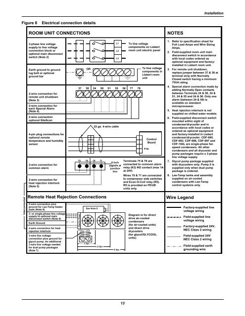
InstallationFigure 8Electrical connection detailsROOM UNIT CONNECTIONSNOTES3-phase line voltagesupply to line voltageconnection block oroptional main disconnectswitch (Note 2)Earth ground to groundlug bolt or optionalground bar2-wire connection forremote unit shutdown(Note 3)2-wire connection foreach Special Alarm(Note 4)2-wire connectionoptional SiteScan4-pin plug connections foroptional remotetemperature and humiditysensor2-wire connection forcommon alarm2-wire connection forheat rejection interlock(Note 5)OR37 38 24 50 51 55 56 77 7875 76 70 71L1L2L322 ga. 4-wire cable6-inchpigtails atjunctionboxTo line voltagecomponents on <strong>Liebert</strong>room unit electric panelTo line voltagecomponents in<strong>Liebert</strong> roomunitP16ControlBoardTerminals 75 & 76 areconnected to common alarmrelay (K3) NO contact (max 1Aat 24V)Wires 70 & 71 are connectedto compressor side switchesand Econ-O-Coil relay (R5).R5 is provided on FE/UEunits only.1. Refer to specification sheet forFull Load Amps and Wire SizingAmps.2. Field-supplied room unit maindisconnect switch in accordancewith local codes ordered asoptional equipment and factoryinstalledin <strong>Liebert</strong> room unit.3. For remote unit shutdown,replace jumper between 37 & 38 atterminal strip with NormallyClosed switch having a minimum75VA rating.4. Special alarm connection made byadding Normally Open contactsbetween Terminals 24 & 50, 24 &51, 24 & 55 and 24 & 56. Only onealarm (between 24 & 50) isavailable on standardmicroprocessor.5. Heat rejection interlock is notsupplied on chilled water models.6. Field-supplied disconnect switchmounted within sight ofcondenser/drycooler and inaccordance with local codes orordered as optional equipmentand factory-installed in <strong>Liebert</strong>condenser/drycooler. CDF-065,CDF-083, CDF-086, CDF-097 andCDF-104L are single-phase fanspeed condensers. All othercondensers and all drycooler andpump packages require a 3-phaseline voltage supply.7. Glycol pump package suppliedwith drycoolers only. Pump 2 issupplied only when dual pumppackage is ordered.8. Lee-Temp tanks and assemblysupplied on air-cooledcondensers with Lee-Tempcontrol systems only.InterconnectedRemote Heat Rejection Connections2-wire connection plusground for Lee-Temp heaterpads (Note 8)3- or single-phase line voltagesupply to optional maindisconnect switch (Note 6)Earth Ground2-wire connection for heatrejection interlock3-wire line voltageconnection plus ground forglycol pump. An additional3-wire line voltage neededfor dual pump packages(Note 7).Electric Panel1See Note 821 fan2 fan3 fanDiagram is for directdrive air-cooledcondensers(for air-cooled units)and direct drivedrycoolers(for glycol/GLYCOOLunits).Wire LegendFactory-supplied linevoltage wiringField-supplied linevoltage wiringFactory-supplied 24V,NEC Class 2 wiringField-supplied 24VNEC Class 2 wiringField-supplied earthgrounding wire13