Liebert Deluxe System/3 - DX
Liebert Deluxe System/3™ - DX
Liebert Deluxe System/3™ - DX

You also want an ePaper? Increase the reach of your titles
YUMPU automatically turns print PDFs into web optimized ePapers that Google loves.
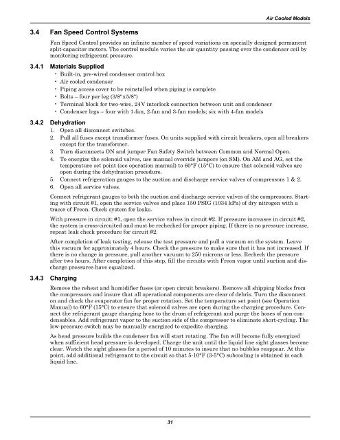
3.4 Fan Speed Control <strong>System</strong>sAir Cooled ModelsFan Speed Control provides an infinite number of speed variations on specially designed permanentsplit-capacitor motors. The control module varies the air quantity passing over the condenser coil bymonitoring refrigerant pressure.3.4.1 Materials Supplied•Built-in, pre-wired condenser control box• Air cooled condenser• Piping access cover to be reinstalled when piping is complete• Bolts – four per leg (3/8"x5/8")• Terminal block for two-wire, 24V interlock connection between unit and condenser• Condenser legs – four with 1-fan, 2-fan and 3-fan models; six with 4-fan models3.4.2 Dehydration1. Open all disconnect switches.2. Pull all fuses except transformer fuses. On units supplied with circuit breakers, open all breakersexcept for the transformer.3. Turn disconnects ON and jumper Fan Safety Switch between Common and Normal Open.4. To energize the solenoid valves, use manual override jumpers (on SM). On AM and AG, set thetemperature set point (see operation manual) to 60°F (15°C) to ensure that solenoid valves areopen during the dehydration procedure.5. Connect refrigeration gauges to the suction and discharge service valves of compressors 1 & 2.6. Open all service valves.Connect refrigerant gauges to both the suction and discharge service valves of the compressors. Startingwith circuit #1, open the service valves and place 150 PSIG (1034 kPa) of dry nitrogen with atracer of Freon. Check system for leaks.With pressure in circuit: #1, open the service valves in circuit #2. If pressure increases in circuit #2,the system is cross-circuited and must be rechecked for proper piping. If there is no pressure increase,repeat leak check procedure for circuit #2.After completion of leak testing, release the test pressure and pull a vacuum on the system. Leavethis vacuum for approximately 4 hours. Check the pressure to make sure that it has not increased. Ifthere is no change in pressure, pull another vacuum to 250 microns or less. Recheck the pressureafter two hours. After completion of this step, fill the circuits with Freon vapor until suction and dischargepressures have equalized.3.4.3 ChargingRemove the reheat and humidifier fuses (or open circuit breakers). Remove all shipping blocks fromthe compressors and insure that all operational components are clear of debris. Turn the disconnecton and check the evaporator fan for proper rotation. Set the temperature set point (see OperationManual) to 60°F (15°C) to ensure that solenoid valves are open during the charging procedure. Connectthe refrigerant gauge charging hose to the drum of refrigerant and purge the hoses of non-condensables.Add refrigerant vapor to the suction side of the compressor to eliminate short-cycling. Thelow-pressure switch may be manually energized to expedite charging.As head pressure builds the condenser fan will start rotating. The fan will become fully energizedwhen sufficient head pressure is developed. Charge the unit until the liquid line sight glasses becomeclear. Watch the sight glasses for a period of 10 minutes to insure that no bubbles reappear. At thispoint, add additional refrigerant to the circuit so that 5-10°F (3-5°C) subcooling is obtained in eachliquid line.31