GV-IPCam H.264
GV-IPCam H.264
GV-IPCam H.264
- No tags were found...

You also want an ePaper? Increase the reach of your titles
YUMPU automatically turns print PDFs into web optimized ePapers that Google loves.
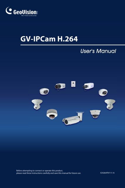
<strong>GV</strong>-<strong>IPCam</strong> <strong>H.264</strong>User's ManualBefore attempting to connect or operate this product,please read these instructions carefully and save this manual for future use.ICH264TIV111-A
© 2012 GeoVision, Inc. All rights reserved.Under the copyright laws, this manual may not be copied, in whole or inpart, without the written consent of GeoVision.Every effort has been made to ensure that the information in this manual isaccurate. GeoVision, Inc. makes no expressed or implied warranty of anykind and assumes no responsibility for errors or omissions. No liability isassumed for incidental or consequential damages arising from the use ofthe information or products contained herein. Features and specificationsare subject to change without notice. Note: no SD/SDHC card slot or localstorage function for Argentina.GeoVision, Inc.9F, No. 246, Sec. 1, Neihu Rd.,Neihu District, Taipei, TaiwanTel: +886-2-8797-8377Fax: +886-2-8797-8335http://www.geovision.com.twTrademarks used in this manual: GeoVision, the GeoVision logo and <strong>GV</strong>series products are trademarks of GeoVision, Inc. Windows and WindowsXP are registered trademarks of Microsoft Corporation.May 2012
Safety NoticeFCC Compliance for <strong>GV</strong>-CBW120/220This device complies with Part 15 of the FCC Rules. Operation is subject tothe following two conditions: (1) this device may not cause harmfulinterference and (2) this device must accept any interference received,including interference that may cause undesired operation of the device.UL Certification for <strong>GV</strong>-MFD120/130/220/320/520The <strong>GV</strong>-IPCAM <strong>H.264</strong> uses a 3.0V CR2032 Lithium battery as the powersupply for its internal real-time clock (RTC). The battery should not bereplaced unless required!If the battery does need replacing, please observe the following:• Danger of Explosion if battery is incorrectly replaced• Replace only with the same or equivalent battery, as recommendedby the manufacturer• Dispose of used batteries according to the manufacturer'sinstructionsI
PrefaceWelcome to the <strong>GV</strong>-IPCAM <strong>H.264</strong> User’s Manual.The <strong>GV</strong>-IPCAM <strong>H.264</strong> has a series of models designed to meet differentneeds. This Manual is designed for the following models and firmwareversions:Note:1. <strong>GV</strong>-<strong>IPCam</strong> <strong>H.264</strong> with 128 MB flash memory is only supported inV1.09 or later. To look up your camera’s flash memory, seeAppendix I Supported Firmware for Flash Memory.2. To upgrade your camera to firmware V1.09 or later, it is required touse <strong>GV</strong> IP Device Utility V8.5.3.0.ModelBox CameraModel Number<strong>GV</strong>-BX110D<strong>GV</strong>-BX120D<strong>GV</strong>-BX130D-0<strong>GV</strong>-BX130D-1<strong>GV</strong>-BX140DW<strong>GV</strong>-BX220D-0<strong>GV</strong>-BX220D-1<strong>GV</strong>-BX220D-2<strong>GV</strong>-BX220D-3<strong>GV</strong>-BX320D-0<strong>GV</strong>-BX321D-1<strong>GV</strong>-BX520D-0Fixed LensVarifocal LensVarifocal LensVarifocal LensFixed LensVarifocal LensFirmwareVersionV1.08V1.11II
ModelIR Arctic BoxCameraModel NumberFirmwareVersion<strong>GV</strong>-BX120D-E<strong>GV</strong>-BX220D-E<strong>GV</strong>-BX320D-EVarifocal Lens V1.11<strong>GV</strong>-BX520D-E<strong>GV</strong>-MFD110 V1.08Mini FixedDome<strong>GV</strong>-MFD120<strong>GV</strong>-MFD130<strong>GV</strong>-MFD220<strong>GV</strong>-MFD320<strong>GV</strong>-MFD520Fixed Lens V1.11Mini FixedRuggedDome<strong>GV</strong>-MDR120<strong>GV</strong>-MDR220Fixed Lens V1.11<strong>GV</strong>-MDR320<strong>GV</strong>-MDR520<strong>GV</strong>-BL110D Varifocal Lens V1.08Bullet Camera<strong>GV</strong>-BL120D<strong>GV</strong>-BL130D<strong>GV</strong>-BL220D<strong>GV</strong>-BL320DVarifocal Lens V1.11PTZ Camera <strong>GV</strong>-PTZ010DNTSCV1.08PALPT Camera <strong>GV</strong>-PT110D V1.08III
ModelFixed IPDomeCube CameraWirelessCube CameraModel Number<strong>GV</strong>-FD120D<strong>GV</strong>-FD220D<strong>GV</strong>-FD320D<strong>GV</strong>-CB120<strong>GV</strong>-CB220<strong>GV</strong>-CBW120<strong>GV</strong>-CBW220FirmwareVersionVarifocalV1.11LensFixed Lens V1.11Fixed Lens V1.11V
ContentsNaming and Definition...................................................XVIOptions ..........................................................................XVIINote for Connecting to <strong>GV</strong>-System............................XVIIINote for Adjusting Focus and Zoom............................XIXNote for Installing Camera Outdoor..............................XXChapter 1 Introduction .....................................................11.1 System Requirement ..................................................................7Chapter 2 Box Camera .....................................................82.1 Packing List...............................................................................102.2 Features.....................................................................................112.2.1 <strong>GV</strong>-BX140DW with WDR Function ......................................122.3 Overview....................................................................................132.3.1 <strong>GV</strong>-BX110D........................................................................132.3.2 <strong>GV</strong>-BX120D / 130D Series / 140DW / 220D Series / 320DSeries / 520D-0.............................................................................162.4 Connecting the Camera............................................................182.4.1 <strong>GV</strong>-BX110D........................................................................182.4.2 <strong>GV</strong>-BX120D / 130D Series / 140DW / 220D Series / 320DSeries / 520D-0.............................................................................202.5 Accessory Installation ..............................................................222.5.1 C-Mount Lenses..................................................................222.5.2 Infrared Illuminators (Optional) ............................................242.6 I/O Terminal Block ....................................................................252.6.1 Pin Assignment ...................................................................252.6.2 Connecting to <strong>GV</strong>-Relay V2 (Optional) ................................27VI
Chapter 3 IR Arctic Box Camera ...................................293.1 Packing List...............................................................................303.2 Features.....................................................................................313.3 Overview....................................................................................323.4 Installation.................................................................................333.5 Connecting the Camera............................................................373.5.1 Wire Definition.....................................................................373.6 Notice for Using the IR Arctic Box Camera.............................393.6.1 Enabling IR LED after Loading Default ................................393.6.2 Disabling Status LED under Low Light Conditions ...............40Chapter 4 Mini Fixed Dome & Mini Fixed RuggedDome………...………………………………………………...414.1 Packing List...............................................................................424.2 Features.....................................................................................434.3 Overview....................................................................................454.3.1 <strong>GV</strong>-MFD110.........................................................................454.3.2 <strong>GV</strong>-MFD120 / 130 / 220 / 320 / 520......................................464.3.3 <strong>GV</strong>-MDR120 / 220 / 320 / 520 ..............................................474.4 Installation.................................................................................494.4.1 <strong>GV</strong>-MFD Series....................................................................494.4.2 <strong>GV</strong>-MDR Series ...................................................................514.5 Connecting the Camera.............................................................544.5.1 Wire Definition......................................................................544.5.2 Power and Network Connection ...........................................554.5.3 Vehicle Installation ...............................................................56Chapter 5 Bullet Camera ................................................575.1 Packing List...............................................................................585.2 Features.....................................................................................595.3 Overview.....................................................................................60VII
5.4 Installation.................................................................................615.4.1 Connecting the Camera ......................................................625.4.2 Adjusting the Angles ...........................................................665.4.3 Adjusting Lens and Inserting a Micro SD Card.....................705.4.4 Installing the Sun-Shield Cover ...........................................72Chapter 6 PTZ Camera ...................................................736.1 Packing List...............................................................................746.2 Features.....................................................................................756.3 Overview....................................................................................766.4 Installation.................................................................................786.4.1 Ceiling Mount......................................................................786.4.2 L-Shaped Wall Mount..........................................................806.5 Connecting the Camera............................................................836.6 Focus Adjustment.....................................................................846.7 I/O Terminal Block ....................................................................856.7.1 Pin Assignment ...................................................................856.7.2 Voltage Load Expansion (Optional) .....................................866.8 PTZ Control ...............................................................................876.8.1 The PTZ Control Panel.........................................................876.8.2 Automatic Focus ..................................................................896.8.3 PTZ Camera Settings...........................................................896.8.4 Image Settings.....................................................................916.8.5 Preset Settings.....................................................................946.8.6 Sequence Settings...............................................................976.8.7 Auto Pan Settings ................................................................996.8.8 System Configuration........................................................102Chapter 7 PT Camera....................................................1037.1 Packing List.............................................................................1037.2 Features...................................................................................105VIII
7.3 Overview..................................................................................1067.4 Installation...............................................................................1087.5 Connecting the Camera..........................................................1087.6 Focus Adjustment...................................................................1087.7 I/O Terminal Block ..................................................................1097.7.1 Pin Assignment .................................................................1097.7.2 Voltage Load Expansion (Optional) ...................................1097.8 PT Control ...............................................................................110Chapter 8 Vandal Proof IP Dome.................................1128.1 Packing List.............................................................................1138.2 Features...................................................................................1148.3 Overview..................................................................................1158.4 Installation...............................................................................1168.4.1 Hard-Ceiling Mount ...........................................................1168.4.2 In-Ceiling Mount................................................................1218.5 Connecting the Camera..........................................................1248.5.1 Wire Definition...................................................................1248.5.2 Power Connection............................................................. 1258.5.3 Voltage Load Expansion (Optional) ...................................126Chapter 9 Fixed IP Dome .............................................1279.1 Packing List.............................................................................1289.1.1 Packing List for Hard-Ceiling Mount...................................1289.1.2 Packing List for In-Ceiling Mount .......................................1299.2 Features...................................................................................1309.3 Overview..................................................................................1319.4 Installation...............................................................................1339.4.1 Hard-Ceiling Mount ...........................................................1339.4.2 In-Ceiling Mount................................................................1379.4.3 Wall-Surface Mount...........................................................141IX
9.5 Connecting the Camera..........................................................1439.6 I/O Terminal Block ..................................................................1449.6.1 Pin Assignment .................................................................1449.6.2 Voltage Load Expansion (Optional) ...................................145CHAPTER 10 Cube & Wireless Camera......................14610.1 Packing List...........................................................................14710.2 Features.................................................................................14810.3 Overview................................................................................14910.4 Installation.............................................................................15010.5 Connecting the Camera........................................................152Chapter 11 Getting Started ..........................................15311.1 Accessing the Live View.......................................................15311.1.1 Checking the Dynamic IP Address...................................15511.1.2 Configuring the IP Address..............................................15711.1.3 Configuring the Wireless Connection............................... 15911.2 Adjusting Image Clarity ........................................................16211.2.1 Using Focus Adjustment Cap ..........................................16511.2.2 Locations of Adjustment Screws......................................16711.3 Configuring the Basics.........................................................169Chapter 12 Accessing the Camera..............................17012.1 Accessing Your Surveillance Images ..................................17012.2 Functions Featured on the Main Page.................................17212.2.1 The Live View Window ....................................................17312.2.2 The Control Panel of the Live View Window ....................17612.2.3 Snapshot of Live Video....................................................18112.2.4 Video Recording..............................................................18112.2.5 Wide Angle Dewarpping..................................................182X
12.2.6 Picture-in-Picture and Picture-and-Picture View............... 18312.2.7 Alarm Notification............................................................18612.2.8 Video and Audio Configuration ........................................18812.2.9 Remote Configuration .....................................................18912.2.10 Camera Name Display ..................................................18912.2.11 Image Enhancement .....................................................18912.2.12 Visual PTZ ....................................................................19012.2.13 I/O Control.....................................................................19312.2.14 Visual Automation .........................................................19412.2.15 Network Status..............................................................195Chapter 13 Administrator Mode ..................................19613.1 Video and Motion ..................................................................19813.1.1 Video Settings................................................................. 19913.1.2 Motion Detection .............................................................20613.1.3 Privacy Mask...................................................................20813.1.4 Text Overlay....................................................................20913.1.5 Tampering Alarm.............................................................21113.1.6 Visual Automation ...........................................................21313.2 I/O Settings............................................................................21513.2.1 Input Settings..................................................................21513.2.2 Output Settings ...............................................................21713.2.3 PTZ Settings ...................................................................21813.3 Events and Alerts..................................................................21913.3.1 E-mail .............................................................................22013.3.2 FTP.................................................................................22213.3.3 Center V2........................................................................22513.3.4 VSM................................................................................22713.3.5 Backup Center ................................................................ 22913.3.6 Video Gateway / Recording Server..................................23213.3.7 ViewLog Server............................................................... 235XI
13.3.8 RTSP..............................................................................23613.4 Monitoring .............................................................................23713.5 Recording Schedule .............................................................23913.5.1 Recording Schedule Settings ..........................................23913.5.2 I/O Monitoring Settings....................................................24013.6 Remote ViewLog ...................................................................24113.7 Network .................................................................................24213.7.1 LAN Configuration...........................................................24213.7.2 Wireless Client Mode ......................................................24413.7.3 Advanced TCP/IP............................................................24613.7.4 IP Filter Settings..............................................................25013.7.5 SNMP Settings................................................................25113.8 Management..........................................................................25313.8.1 Date & Time Settings ......................................................25313.8.2 GPS Maps Settings.........................................................25513.8.3 Storage Settings.............................................................. 25713.8.4 User Account ..................................................................25913.8.5 Log Information ...............................................................26013.8.6 System Log.....................................................................26113.8.7 Tools...............................................................................263Chapter 14 Recording and Playback ..........................26514.1 Recording..............................................................................26514.2 Playback ................................................................................26614.2.1 Playback Using the Memory Card....................................26614.2.2 Playback over Network....................................................26814.2.3 Access to the Recorded Files through FTP Server........... 26914.2.4 Playback of Daylight Saving Time Events........................269XII
Chapter 15 Advanced Applications ............................27115.1 Upgrading System Firmware................................................27115.1.1 Using the Web Configuration Interface ............................27315.1.2 Using the IP Device Utility ...............................................27415.2 Backing Up and Restoring Settings.....................................27615.3 Restoring to Factory Default Settings .................................27815.4 Verifying Watermark .............................................................28815.4.1 Accessing AVI Files.........................................................28915.4.2 Running Watermark Proof ...............................................29015.4.3 The Watermark Proof Window.........................................29115.5 Downloading Videos from the SD Card...............................29215.5.1 Installing the <strong>GV</strong>-SDCardSync Utility ...............................29315.5.2 The <strong>GV</strong>-SDCardSync Utility Window ...............................297Chapter 16 DVR Configurations ..................................29916.1 Setting up an IP Camera.......................................................30316.1.1 Customizing IP Camera Settings .....................................30616.2 Remote Monitoring with Multi View .....................................30816.2.1 Connecting to the IP Camera ..........................................30816.3 Remote Monitoring with E-Map............................................30916.3.1 Creating an E-Map for the IP Camera..............................30916.3.2 Connecting to the IP Camera ..........................................310Chapter 17 CMS Configurations..................................31117.1 Center V2...............................................................................31117.2 VSM........................................................................................31417.3 Dispatch Server.....................................................................315Chapter 18 Mobile Phone Connection........................31718.1 PDA........................................................................................319XIII
18.1.1 Installing <strong>GV</strong>iew V2 ......................................................... 31918.1.2 Activating the <strong>GV</strong>iew Function.........................................32018.1.3 Connecting to the IP Camera ..........................................32118.1.4 Playing Back the Recordings from the IP Camera............ 32318.1.5 Other Functions...............................................................32418.2 Windows Smartphone ..........................................................32918.2.1 Installing MSView V2 / V3 ...............................................32918.2.2 Activating the MSView V2 / V3 Function.......................... 33018.2.3 Connecting to the IP Camera ..........................................33118.2.4 Playing Back the Recordings from the IP Camera............ 33318.2.5 Other Functions...............................................................33418.3 Symbian Smartphone ...........................................................33518.3.1 Installing SSView V3 ....................................................... 33518.3.2 Activating the SSView V3 Function.................................. 33618.3.3 Connecting to the IP Camera ..........................................33718.3.4 Quick Connection............................................................33818.3.5 Playing Back the Recordings from the IP Camera............ 33818.3.6 Other Functions...............................................................33918.4 3G Mobile Phone...................................................................34018.4.1 Activating the 3G Mobile Phone Function ........................ 34018.4.2 Connecting to the IP Camera ..........................................34118.5 Android Smartphone ............................................................34318.5.1 Connecting to <strong>GV</strong>-IPCAM <strong>H.264</strong> .....................................34418.6 iPhone, iPod Touch and iPad...............................................34718.6.1 Installing <strong>GV</strong>-Eye V1.0 / HD V1.0 ....................................34718.6.2 Connecting to <strong>GV</strong>-IPCAM <strong>H.264</strong> .....................................348Specifications: Box Camera .........................................351Specifications: IR Arctic Box Camera .........................365Specifications: Mini Fixed & Rugged Dome1 .............373XIV
Specifications: Bullet Camera ......................................387Specifications: PTZ Camera .........................................395Specifications: PT Camera ...........................................400Specifications: Vandal Proof IP Dome.........................405Specifications: Fixed IP Dome .....................................413Specifications: Cube Camera & Wireless Cube Camera...........................................................................................420Appendix ........................................................................425A. Settings for Internet Explorer 8 ...............................................425B. Supported Lenses for Box Camera.........................................426C. Resolution and Frame Rate .....................................................427D. Support Lists ............................................................................432E. RTSP Protocol Command ........................................................438F. The CGI Command ...................................................................439G. Dual Stream Support List ........................................................441H. Power Supply Support List......................................................444I. Supported Firmware for Flash Memory....................................445XV
Naming and Definition<strong>GV</strong>-SystemGeoVision Analog and Digital Video Recording Software.The <strong>GV</strong>-System also refers to <strong>GV</strong>-Multicam System,<strong>GV</strong>-NVR System, <strong>GV</strong>-DVR System and <strong>GV</strong>-HybridDVR System at the same time.XVI
OptionsOptional devices can expand your camera’s capabilities and versatility.Contact your dealer for more information.Device<strong>GV</strong>-IR LED<strong>GV</strong>-PA191 PoEAdapter<strong>GV</strong>-MountAccessoriesDescriptionA mountable infrared LED device that improvesimage performance of Box Cameras under lowlight conditions. Note that the <strong>GV</strong>-IR LED is onlycompatible with <strong>GV</strong>-BX110D and <strong>GV</strong>-IR LED T2is compatible with <strong>GV</strong>-BX120D / 130D Series /140DW / 220D Series / 320D Series / 520D-0.The <strong>GV</strong>-PA191 PoE adapter is designed toprovide power and network connection to thecameras over a single Ethernet cable.The <strong>GV</strong>-Mount Accessories provide acomprehensive lineup of accessories forinstallation on ceiling, wall and pole. For details,see <strong>GV</strong>-Mount Accessories Installation Guide onthe software CD.XVII
Note for Connecting to <strong>GV</strong>-SystemThe <strong>GV</strong>-IPCAM <strong>H.264</strong> is designed to work with <strong>GV</strong>-System, a hybrid ordigital video management system. Note the following when <strong>GV</strong>-IPCAM<strong>H.264</strong> is connected to <strong>GV</strong>-System:1. Normally, the images are recorded to the memory card inserted in the<strong>GV</strong>-IP Camera <strong>H.264</strong> (except <strong>GV</strong>-MFD110 and <strong>GV</strong>-IR Arctic BoxCamera). Once the camera is connected to <strong>GV</strong>-System for videomanagement or the camera’s Live View (Figure 11-3) is accessedthrough the Web browser, the recording to the memory card will bestopped and the recording will be taken control by <strong>GV</strong>-System. Whenthe connection between the camera and <strong>GV</strong>-System is interrupted,the recording to the memory card will be resumed to back up theimages on the camera.2. Once the camera is connected to the <strong>GV</strong>-System, the resolution seton the <strong>GV</strong>-System will override the resolution set on the camera’sWeb interface. You can only change the resolution settings throughthe Web interface when the connection to the <strong>GV</strong>-System isinterrupted.XVIII
Note for Adjusting Focus andZoomWhen adjusting the Focus and Zoom Screws (on Box Camera, IR ArcticBox Camera, Bullet Camera, Vandal Proof IP Dome and Fixed IP Camera),please do not over tighten the Focus and Zoom screws. The screws onlyneed to be as tight as your finger can do it; don't bother using any tools toget them tighter. Doing so can damage the structure of lens.For example,Bullet CameraFixed IP CameraThe maximum torque value for all the zoom and focus screws is 3.9 to4.9 N.cmXIX
Note for Installing Camera OutdoorWhen installing the IR Arctic Box Camera, Bullet Camera, Vandal ProofIP Dome or Mini Fixed Rugged Dome outdoor, be sure that:1. The camera is set up above the junction box to prevent water fromentering the camera along the cables.2. Any PoE, power, audio and I/O cables are waterproofed usingwaterproof silicon rubber or the like.XX
3. After opening the camera cover, ensure the screws are tightenedand the cover is in place.4. To prevent the lens from fogging up, ensure to replace the silica gelbag every time you open the camera, and conceal the gel bag incamera within 2 minutes of exposing to open air. The silica gel bagloses it effectiveness when the dry camera is openedXXI
Chapter 1 IntroductionThe <strong>GV</strong>-IPCAM <strong>H.264</strong> series offers a full range of IP cameras that bringyou the advantage to instantly access live images and monitor surveillanceareas of different environmental conditions from remote sites. Ten seriesare available: Box Camera, Mini Fixed Dome, Mini Fixed Rugged Dome,Bullet Camera, PTZ Camera, PT Camera, Vandal Proof IP Dome, FixedIP Dome, Cube Camera and Wireless Cube Camera. For detailedfeatures of each model, please refer to the corresponding chapter.Model Model No. DescriptionBoxCamera<strong>GV</strong>-BX110D<strong>GV</strong>-BX120D<strong>GV</strong>-BX130D-0<strong>GV</strong>-BX130D-1<strong>GV</strong>-BX140DWFixedLensVarifocalLensVarifocalLensVarifocalLensFixedLensVarifocalLens1.3 MP, <strong>H.264</strong>, D/N,Fixed Iris1.3 MP, <strong>H.264</strong>, D/N,Auto Iris1.3 MP, <strong>H.264</strong>, LowLux, D/N, Auto Iris, f:2.8 ~ 12 mm, F/1.4,1/3’’ CS Lens1.3 MP, <strong>H.264</strong> D/N,Auto Iris, f: 2.8 ~ 12mm, F/1.4, 1/3’’ CSLens1.3 MP, <strong>H.264</strong> D/N,Fixed Iris, f: 4 mm,F/1.5, 1/3’’ CS Lens1 MP, <strong>H.264</strong> D/NWDR Box IP Cam,Fixed Iris, f: 2.8 ~ 12mm, F/1.4, 1/3’’ CSLens
Model Model No. Description<strong>GV</strong>-BX220D-02 MP, <strong>H.264</strong> D/N,Auto Iris, f: 2.8 ~ 8.5mm, F/1.4,1/3” CS Lens<strong>GV</strong>-BX220D-12 MP, <strong>H.264</strong> D/N,Auto Iris, f: 3.1 ~ 8mm, F/1.2,1/3’’ CS Lens<strong>GV</strong>-BX220D-22 MP, <strong>H.264</strong> D/N,Auto Iris, f: 2.8 ~ 6mm, F/1.3,1/3’’ CS LensBoxCamera<strong>GV</strong>-BX220D-3VarifocalLens2 MP, <strong>H.264</strong> D/N,Auto Iris, f: 2.8 ~ 12mm, F/1.4,1/3’’ CS Lens3 MP, <strong>H.264</strong> D/N,<strong>GV</strong>-BX320D-0Auto Iris, f: 3.1 ~ 8mm, F/1.2,1/3’’ CS Lens3 MP, <strong>H.264</strong> D/N,<strong>GV</strong>-BX320D-1Auto Iris, f: 2.8 ~ 6mm, F/1.3,1/3’’ CS Lens<strong>GV</strong>-BX520D-05 MP, <strong>H.264</strong> D/N,Manual Iris,f: 4.5 ~ 10 mm, F/1.6,1/2’’ CS Lens2
1IntroductionModel Model No. Description<strong>GV</strong>-BX120D-E1.3 MP, <strong>H.264</strong>,Low Lux, D/N, AutoIris, f: 2.8 ~ 12 mm,F/1.4, 1/3’’ CSLensIR ArcticBoxCamera<strong>GV</strong>-BX220D-E<strong>GV</strong>-BX320D-EVarifocalLens2 MP, <strong>H.264</strong> D/N,Auto Iris, f: 2.8 ~ 6mm, F/1.3,1/3’’ CS Lens3 MP, <strong>H.264</strong> D/N,Auto Iris, f: 2.8 ~ 6mm, F/1.3,1/3’’ CS Lens5 MP, <strong>H.264</strong> D/N,<strong>GV</strong>-BX520D-EManual Iris, f: 4.5 ~10 mm, F/1.6,1/3’’ CS Lens<strong>GV</strong>-MFD1101.3 MP, <strong>H.264</strong>,Color, Fixed Iris<strong>GV</strong>-MFD1201.3 MP Low Lux<strong>H.264</strong>, Color, FixedIrisMini FixedDome<strong>GV</strong>-MFD130<strong>GV</strong>-MFD220FixedLens1.3 MP <strong>H.264</strong>,Color, Fixed Iris2 MP <strong>H.264</strong>, Color,Fixed Iris<strong>GV</strong>-MFD3203 MP <strong>H.264</strong>, Color,Fixed Iris<strong>GV</strong>-MFD5205 MP <strong>H.264</strong>, Color,Fixed Iris3
Model Model No. DescriptionMini FixedRuggedDomeBulletCameraPTZCamera<strong>GV</strong>-MDR120<strong>GV</strong>-MDR220<strong>GV</strong>-MDR320<strong>GV</strong>-MDR520<strong>GV</strong>-BL110D<strong>GV</strong>-BL120D<strong>GV</strong>-BL130D<strong>GV</strong>-BL220D<strong>GV</strong>-BL320D<strong>GV</strong>-PTZ010DFixedLensVarifocalLensNTSCPAL1.3 MP Low Lux<strong>H.264</strong>, Color, FixedIris2 MP <strong>H.264</strong>, Color,Fixed Iris3 MP <strong>H.264</strong>, Color,Fixed Iris5 MP <strong>H.264</strong>, Color,Fixed Iris1.3 MP, <strong>H.264</strong>,Auto Iris1.3 MP, <strong>H.264</strong>,Low Lux, Auto Iris1.3 MP, <strong>H.264</strong>,Auto Iris2 MP, <strong>H.264</strong>, AutoIris3 MP, <strong>H.264</strong>, AutoIris10x Optical Zoom,D1, <strong>H.264</strong>, D/N,Fixed IrisPTCamera<strong>GV</strong>-PT110D1.3 MP, <strong>H.264</strong>,Fixed Iris4
1IntroductionModel Model No. DescriptionVandalProof IPDomeFixed IPDome<strong>GV</strong>-VD120D(IK10+, Transparent Cover)<strong>GV</strong>-VD121D(IK10+, Smoked Cover)<strong>GV</strong>-VD122D(IK7, Transparent Cover)<strong>GV</strong>-VD123D(IK7, Smoked Cover)<strong>GV</strong>-VD220D(IK10+, Transparent Cover)<strong>GV</strong>-VD221D(IK10+, Smoked Cover)<strong>GV</strong>-VD222D(IK7, Transparent Cover)<strong>GV</strong>-VD223D(IK7, Smoked Cover)<strong>GV</strong>-VD320D(IK10+, Transparent Cover)<strong>GV</strong>-VD321D(IK10+, Smoked Cover)<strong>GV</strong>-VD322D(IK7, Transparent Cover)<strong>GV</strong>-VD323D(IK7, Smoked Cover)<strong>GV</strong>-FD120D<strong>GV</strong>-FD220D<strong>GV</strong>-FD320DVarifocalLensVarifocalLens1.3 MP, <strong>H.264</strong>,Low Lux,Auto Iris2 MP, <strong>H.264</strong>,Auto Iris3 MP, <strong>H.264</strong>,Auto Iris1.3 MP, <strong>H.264</strong>,Low Lux, Auto Iris2 MP, <strong>H.264</strong>, AutoIris3 MP, <strong>H.264</strong>, AutoIris5
Model Model No. DescriptionCubeCameraWirelessCubeCamera<strong>GV</strong>-CB120<strong>GV</strong>-CB220<strong>GV</strong>-CBW120<strong>GV</strong>-CBW220FixedLens1.3 MP, <strong>H.264</strong>,Fixed Iris2 MP, <strong>H.264</strong>,Fixed Iris1.3 MP, <strong>H.264</strong>,Wireless Fixed Iris2 MP, <strong>H.264</strong>,Wireless Fixed Iris6
1Introduction1.1 System RequirementTo perform the <strong>GV</strong>-IPCAM <strong>H.264</strong> operations through Web browser, ensureyour PC is in good network connection, and use one of the following webbrowsers:Microsoft Internet Explorer 7.x or laterGoogle ChromeMozilla FirefoxSafariNote:1 For the users of Internet Explorer 8, additional settings are required.For details, see Appendix A.2 With non-IE browsers,A. Motion Detection, Tampering Alarm, Visual Automation, TextOverlay, two-way audio and GPS map settings are notsupported.B. only the Play function is available on the live view window(Figure 11-3)C. RTSP streaming must be kept as enabled. For more detail, see13.3.8 RTSP.7
Chapter 2 Box CameraThe Box Camera series offers fixed focal or varifocal models, ranging from1.3 to 5 megapixel and is designed with an automatic infrared cut filter forday and night surveillance.Box CameraModel No. Specifications Description<strong>GV</strong>-BX110DFixed LensVarifocal LensMegapixel, Fixed Iris,f:4 mm, F/1.5, 1/3” CSLensMegapixel, Auto Iris,f:4 ~ 9 mm, F/1.4, 1/3”CS Lens1.3 MP,<strong>H.264</strong>, D/N1.3 MP,<strong>H.264</strong>, D/N<strong>GV</strong>-BX120DVarifocal LensMegapixel, Auto Iris,f:2.8 ~ 12 mm, F/1.4,1/3” CS Lens1.3 MP,<strong>H.264</strong>, LowLux, D/N<strong>GV</strong>-BX130D-0Varifocal LensMegapixel, Auto Iris,f: 2.8 ~ 12 mm, F/1.4,1/3’’ CS Lens1.3 MP,<strong>H.264</strong>, D/N<strong>GV</strong>-BX130D-1Fixed LensMegapixel, Fixed Iris,f: 4 mm, F/1.4,1/3’’ CS Lens1.3 MP,<strong>H.264</strong>, D/N
2Box CameraModel No. Specifications Description<strong>GV</strong>-BX140DWMegapixel, Fixed Iris,f: 2.8 ~ 12 mm, F/1.4,1/3’’ CS Lens1 MP, <strong>H.264</strong>,D/N, WDR<strong>GV</strong>-BX220D-0Megapixel, Auto Iris,f:2.8 ~ 8.5 mm, F/1.4,1/3” CS Lens<strong>GV</strong>-BX220D-1<strong>GV</strong>-BX220D-2<strong>GV</strong>-BX220D-3Varifocal LensMegapixel, Auto Iris,f: 3.1 ~ 8 mm,F/1.2, 1/3’’ CS LensMegapixel, Auto Iris,f: 2.8 ~ 6 mm,F/1.3, 1/3’’ CS LensMegapixel, Auto Iris,f: 2.8 ~ 12 mm, F/1.4,1/3’’ CS Lens2 MP, <strong>H.264</strong>,D/N<strong>GV</strong>-BX320D-0<strong>GV</strong>-BX320D-1Megapixel, Auto Iris,f:3.1 ~ 8 mm, F/1.2,1/3” CS LensMegapixel, Auto Iris,f: 2.8 ~ 6 mm, F/1.3,1/3’’ CS Lens3 MP, <strong>H.264</strong>,D/N<strong>GV</strong>-BX520D-0Megapixel, ManualIris, f: 4.5 ~ 10 mm,F/1.6, 1/2’’ CS Lens5 MP, <strong>H.264</strong>,D/N9
2.1 Packing ListBox CameraTerminal BlockFixed Focal or Varifocal Megapixel LensPin Wrench (for <strong>GV</strong>-BX110D only)C-mount Lens Adapter (for <strong>GV</strong>-BX110D only)Six Lens Rings (for <strong>GV</strong>-BX120D / 130D series / 220D series / 520Dseries)One 0.125 mm Lens Ring (for <strong>GV</strong>-BX140DW only)Video Out Wire (not available for <strong>GV</strong>-BX110D)DC 12V Power Adapter<strong>GV</strong>-IPCAM <strong>H.264</strong> Software CD<strong>GV</strong>-IPCAM <strong>H.264</strong> Quick Start Guide<strong>GV</strong>-NVR Software DVD<strong>GV</strong>-NVR Quick Start Guide10
2Box Camera2.2 Features1.3 / 2 / 3 / 5 megapixel progressive scan CMOSDual video streamsFor <strong>GV</strong>-BX110D: Dual streams from <strong>H.264</strong>, MPEG4 or MJPEGFor Box Camera (except <strong>GV</strong>-BX110D): Stream 1 from <strong>H.264</strong> orMJPEG; Stream 2 from <strong>H.264</strong>, MPEG4 or MJPEGFrame rate:Camera ModelFrame Rate<strong>GV</strong>-BX110D Up to 15 fps at 1280 x 1024<strong>GV</strong>-BX120D<strong>GV</strong>-BX130D SeriesUp to 30 fps at 1280 x 1024<strong>GV</strong>-BX140DW Up to 30 fps at 1280 x 720<strong>GV</strong>-BX220D Series Up to 30 fps at 1920 x 1080<strong>GV</strong>-BX320D Series Up to 20 fps at 2048 x 1536<strong>GV</strong>-BX520D-0 Up to 10 fps at 2560 x 1920Day / Night function (with removable IR-cut filter)Wide dynamic range (for <strong>GV</strong>-BX140DW only)Two-way audioOne sensor input and alarm outputTV-out supportMicro SD / SDHC memory card slotMotion detectionTampering alarmVisual automationPrivacy maskText overlayIP address filteringPower supply: DC 12V and PoEMegapixel lens11
Support for iPhone, iPad, Android and 3GPP28 languages on Web interface2.2.1 <strong>GV</strong>-BX140DW with WDR Function<strong>GV</strong>-BX140DW is equipped with a wide dynamic range (WDR) sensor. Thespecial sensor can deal with the scenes having a large difference inforeground and background light intensities, and heighten the detailsvisible in the camera view. An example of WDR in action is shown below.The first image shows the image from a camera without the WDR functionand the second image shows how it looks with WDR function.No WDR: underexposureWDR: perfect exposure12
2Box Camera2.3 Overview2.3.1 <strong>GV</strong>-BX110DFigure 2-1Note: The Zoom Screw and Auto Iris Connector are only available inthe varifocal model.13
No. Name Description1 Audio Out Connects a speaker for audio output.2 Audio In Connects a microphone for audio input.3 DefaultResets all configurations of the <strong>GV</strong>-IPCAM<strong>H.264</strong> to the default factory settings. See15.3 Restoring to Factory Default Settings.4 Memory Card SlotInserts a micro SD/SDHC card to storerecording data.5 Video OutConnects to a portable monitor for settingthe focus and angle of Box Camera duringinitial installation.6 I/O Terminal Block For details, see 2.6 I/O Terminal Block.7 LAN / PoE Connects to a 10/100 Ethernet or PoE.8 DC 12V Connector Connects to power.9 Status LED See Status LED later in this chapter.10 Zoom ScrewAdjusts the zoom of the camera. Thisscrew is not available for <strong>GV</strong>-BX110Dfixed lens type.11 Focus Screw Adjusts the focus of the camera.12 Microphone Records the sounds.13 Auto Iris ConnectorIf the varifocal lens is in use, plug the iriscontrol cable to the connector. Note thatAuto Iris Connector is not functional infixed focal <strong>GV</strong>-BX110D.14
2Box CameraStatus LEDThe status LED is used to reflect the system status of the camera.Status LEDRed Light ONFlashing Red and GreenLightsGreen Light ONDescriptionThe system powers on and succeeds toboot up.The camera is ready for use with networkconnectivity.Error occurs on the system.15
2.3.2 <strong>GV</strong>-BX120D / 130D Series / 140DW / 220D Series /320D Series / 520D-0Figure 2-2Note:1. The Light Sensor (No.11) is only available in <strong>GV</strong>-BX140DW. Keepthe Light Sensor unobscured for accurate light detection.2. The Iris Screw (No.13) is only available for <strong>GV</strong>-BX520D-0.3. The Zoom Screw (No. 15) is not available for <strong>GV</strong>-BX110D (fixedlens model) and <strong>GV</strong>-BX130D-1.16
2Box CameraNo. Name Description1 Video OutConnects to a portable monitor for settingthe focus and angle of Box Camera duringinitial installation.2 Memory Card SlotInserts a micro SD/SDHC card to storerecording data.3 Audio Out Connects a speaker for audio output.4 Audio In Connects a microphone for audio input.5 I/O Terminal Block For details, see 2.6 I/O Terminal Block.6 Power LED Indicates the power is supplied.7 Auto Iris ConnectorPlug the iris control cable to the connector.Note that Auto Iris Connector is notfunctional in <strong>GV</strong>-BX130D-1, <strong>GV</strong>-BX140DWand <strong>GV</strong>-BX520D-0.8 DC 12V Port Connects to power.9 LAN / PoE Connects to a 10/100 Ethernet or PoE.10 Default Resets all configurations of the <strong>GV</strong>-IPCAM<strong>H.264</strong> to the default factory settings. See15.3 Restoring to Factory Default Settings.11 Light Sensor Detects light to switch between day andnight mode.12 Focus Screw Adjusts the focus of the camera.13 Iris Screw Adjusts the iris of the camera.14 Microphone Records the sounds.15 Zoom Screw Adjusts the zoom of the camera.16 Status LED Turns on when the unit is ready for use.17
2.4 Connecting the CameraThe Box Camera is designed for indoor use. Please make sure theinstalling site is shielded from rain and moisture.2.4.1 <strong>GV</strong>-BX110D3 3 43762Figure 2-3518
2Box Camera1. If you are using the auto iris model, plug the iris control cable to theAuto Iris Connector on the camera.2. Use a standard network cable to connect the camera to your network.3. Optionally connect a speaker and an external microphone.4. Optionally connect a monitor using an RCA video-out wire. Enablethis function by selecting your signal format at the TV Out field on theWeb interface. See 13.1.1 Video Settings.5. Connect power using one of the following methods: plugging the supplied power adapter to the DC jack. using the Power over Ethernet (PoE) function and the power willbe provided over the network cable.6. Optionally connect to input / output devices or an infrared illuminator.For details, see 2.5.2 Infrared Illuminator and 2.6 I/O Terminal Block.7. The status LED of the camera will be red.8. You are ready to access the live view, adjust the image clarity andconfigure the basics. See Getting Started, Chapter 11.19
2.4.2 <strong>GV</strong>-BX120D / 130D Series / 140DW / 220D Series /320D Series / 520D-0Figure 2-41. If you are using the auto iris model, plug the iris control cable to theAuto Iris Connector on the camera.2. Use a standard network cable to connect the camera to your network.3. Optionally connect a speaker and an external microphone.4. Optionally connect a monitor using a Video Out wire. Enable thisfunction by selecting your signal format at the TV Out field on theWeb interface. See 13.1.1 Video Settings.5. Optionally connect to input / output devices or an infrared illuminator.For details, see 2.5.2 Infrared Illuminator and 2.6 I/O Terminal Block.6. Connect power using one of the following methods: plugging the supplied power adapter to the power port. using the Power over Ethernet (PoE) function and the power willbe provided over the network cable.7. The status LED of the camera will be on.20
2Box Camera8. You are ready to access the live view, adjust the image clarity andconfigure the basics. See Getting Started, Chapter 11.21
2.5 Accessory Installation2.5.1 C-Mount LensesIf you use a C-mount lens, it requires a certain distance from the camera’simaging chip to focus the lens. Mount the supplied C-mount lens adapter /lens ring to the camera, and then attach the lens onto the camera body.• <strong>GV</strong>-BX110DInstall the supplied C-mount lens adapter to extend focal length of <strong>GV</strong>-BX110D as illustrated below.C-mount lens adapterFigure 2-522
2Box Camera• <strong>GV</strong>-BX120D / 130D Series / 140DW / 220D Series / 320D Series /520D-0Three types of C-mount lens rings are provided for <strong>GV</strong>-BX120D / 130DSeries / 220D Series / 320D Series / 520D-0: 0.188 mm (transparent color) x 2 0.125 mm (black color with a glossy surface) x 2 0.254 mm (black color with a matt surface) x 2For <strong>GV</strong>-BX140DW, a 0.125 mm is provided.Note: The C-mount lens rings are specially designed for <strong>GV</strong>-BX120D /130D Series / 140DW / 220D Series / 320D Series / 520D-0. Besidesthe supplied C-mount lens rings, each of these models has alreadyincluded with the necessary lens ring.Figure 2-623
2.5.2 Infrared Illuminators (Optional)If you use an infrared (IR) illuminator with I/O function, follow the stepsbelow to install it.1. Connect the infrared illuminator to the terminal block on the camera.See 2.6 The I/O Terminal Block.2. Access the Web interface of the camera.3. Select Video and Motion, select Video Settings, select Streaming 1and set the IR Check Function option to be Trigger by Input orTrigger IR by D/N.4. Click Apply.For the Trigger by Input or Trigger IR by D/N function and D/N sensitivitysettings, see 13.1.1 Video Settings.24
2Box Camera2.6 I/O Terminal BlockThe terminal block, located on the back panel of the Box Camera, providesthe interface to one input and one output devices. The I/O terminal blockcan be used for applications such as motion detection, event alerts via E-Mail and FTP, and center monitoring through Center V2 and VSM.2.6.1 Pin AssignmentThe pin assignment for the I/O terminal block:• <strong>GV</strong>-BX110D12345Figure 2-7Pin Function1 Input +2 Input -3 Output Common4 Output N/C5 Output N/OThe <strong>GV</strong>-BX110D only supports the input device of Wet Contact, 7V ~ 30V.For the output point, please check if your output device meets the followingAbsolute Maximum Ratings before connecting it to the output point.Breakdown Voltage277V AC, 30V DCContinuous Load Current 5A (NO), 3A (NC)Note: Absolute Maximum Ratings are those values beyond whichdamage to the camera may occur. Continuous operation of the camera atthe absolute rating level may affect the camera reliability.25
• <strong>GV</strong>-BX120D / 130D Series / 140DW / 220D Series / 320D Series /520D-0The <strong>GV</strong>-BX120D / 130D Series / 140DW / 220D Series / 320D Series /520D-0 support one digital input and one digital output of dry contact.PinFunction1 Digital Input2 GNDFigure 2-8 3 Digital OutputFor details on how to enable an installed I/O device, see 13.2 I/O Settings.26
2Box Camera2.6.2 Connecting to <strong>GV</strong>-Relay V2 (Optional)The Box Camera (except <strong>GV</strong>-BX110D) can only drive a maximum load of200mA 5V DC. Connect the camera to a <strong>GV</strong>-Relay V2 module (optionalproduct) to expand the maximum voltage load. See a comparison onmaximum voltage loads with and without <strong>GV</strong>-Relay:ModelsMaximum Voltage LoadWithout <strong>GV</strong>-Relay V2With <strong>GV</strong>-Relay V2<strong>GV</strong>-BX110D<strong>GV</strong>-BX120D<strong>GV</strong>-BX130D Series<strong>GV</strong>-BX140DW<strong>GV</strong>-BX220D Series<strong>GV</strong>-BX320D Series<strong>GV</strong>-BX520D-010A 250V AC10A 125V AC5A 100V DC200 mA 5V DCN/A10A 250V AC,10A 125V AC,5A 100V DCNote: <strong>GV</strong>-BX110D contains built-in relay. Therefore, it does not requirea <strong>GV</strong>-Relay to maximize its voltage load.27
To connect the Box Camera to <strong>GV</strong>-Relay V2, refer to the figure and tablebelow.Figure 2-9<strong>GV</strong>-Relay V2COMDO1I/O Terminal BlockPin 2 (GND)Pin 3 (Digital Output)28
Chapter 3 IR Arctic Box CameraThe IR Arctic Box Camera series is a variant of the Box Camera series.They are outdoor cameras with IP66 rating. They are designed for day andnight surveillance in environments with extreme temperatures.IR Arctic Box CameraModel No. Specifications Description<strong>GV</strong>-BX120D-EMegapixel, Auto Iris,f: 2.8 ~ 12 mm, F/1.4,1/3” CS Lens1.3 MP,<strong>H.264</strong>, LowLux, D/N<strong>GV</strong>-BX220D-EMegapixel, Auto Iris,f: 2.8 ~ 6 mm,F/1.3, 1/3’’ CS Lens2 MP, <strong>H.264</strong>,D/N<strong>GV</strong>-BX320D-EVarifocal LensMegapixel, Auto Iris,f: 2.8 ~ 6 mm, F/1.3,1/3’’ CS Lens3 MP, <strong>H.264</strong>,D/N<strong>GV</strong>-BX520D-EMegapixel, ManualIris, f: 4.5 ~ 10 mm,F/1.6, 1/2’’ CS Lens5 MP, <strong>H.264</strong>,D/N
3.1 Packing List IR Arctic Box Camera Screw Anchor x 4 Screw x 4 Washer x 4 Big Torx Wrench Small Torx Wrench Silica Gel Bag x 2 Sticker x 2 <strong>GV</strong>-PA481<strong>GV</strong>-PA481 Power Cord<strong>GV</strong>-IPCAM <strong>H.264</strong> Software CD<strong>GV</strong>-IPCAM <strong>H.264</strong> Quick Start Guide<strong>GV</strong>-NVR Software DVD<strong>GV</strong>-NVR Quick Start Guide30
3IR Arctic Box Camera3.2 Features1.3 / 2 / 3 / 5 megapixel progressive scan CMOSStream 1 from <strong>H.264</strong> or MJPEG; Stream 2 from <strong>H.264</strong>, MPEG4 orMJPEGFrame rate:Camera ModelFrame Rate<strong>GV</strong>-BX120D-E Up to 30 fps at 1280 x 1024<strong>GV</strong>-BX220D-E Up to 30 fps at 1920 x 1080<strong>GV</strong>-BX320D-E Up to 20 fps at 2048 x 1536<strong>GV</strong>-BX520D-E Up to 10 fps at 2560 x 1920Day / Night function (with removable IR-cut filter)IP66 ratingBuilt-in heater and fanSupport for TV-outTwo-way audioMotion detectionTampering alarmPrivacy maskText overlayIP address filteringPower supplied through PoE (IEEE 802.3at)Megapixel lensSupport for iPhone, iPad, Android and 3GPP28 languages on Web interface31
3.3 OverviewFigure 3-1Note: The Iris Screw (No. 7) is only available in <strong>GV</strong>-BX520D-E.No. Name Description1 Silica gel bagDesiccant that keeps the camera housingdry.2 IR power plug Supplies power to the built-in IR LEDs.3 Focus Screw Adjusts the focus of the camera.4 Module screw Holds the module in place.5 Status LED Turns on when the unit is ready for use.6 Zoom Screw Adjusts the zoom of the camera.7 Iris Screw Adjusts the iris of the camera.32
3IR Arctic Box Camera3.4 InstallationThe IR Arctic Box Camera is designed for outdoor use.1. Mark the installation site and drill four holes for screw anchors.2. Insert the supplied screw anchors.3. Secure the camera to the wall using the supplied washers and screws.Figure 3-24. Connect the camera to the network and supply power via the PoEcable. See 3.5 Connecting the Camera.5. Access the live view. See 11.1 Accessing the Live View.6. Based on the live view, adjust the angle of the camera. Loosen theindicated screw with the supplied big torx wrench and adjust the joint.Figure 3-333
Tilt AdjustmentFigure 3-4Pan AdjustmentFigure 3-57. Based on the live view, adjust the focus, zoom and iris (in <strong>GV</strong>-BX520D-E only) of the camera.Unscrew the cover with the supplied small torx wrench.Figure 3-634
3IR Arctic Box CameraHold the connectors and unplug them.Figure 3-7Important: Unscrew and remove the cover carefully. Pulling the coveroff may cause damages to the inner wiring of the camera.Adjust the focus, zoom and iris screws.Figure 3-835
8. Replace the silica gel bag. Paste the sticker to the front side of thesilica gel bag. Press the sticker several times to make sure it adheresproperly. Paste the silica gel bag to the indicated place.Figure 3-9Important:1. Be sure that the new silica gel bag is concealed in the camerahousing within 2 minutes of exposing to open air.2. To prevent the lens from fogging up, you must replace the silicagel bag every time you open the camera. The gel bag loses itseffectiveness when the dry camera is opened.9. Refer to step 7 to plug the connectors and secure the camera cover.36
3IR Arctic Box Camera3.5 Connecting the Camera3.5.1 Wire DefinitionFigure 3-10No. Wire Color Definition1 Black (thick) PoE2 Black BNC TV out3 Green RCA Audio Out4 Pink RCA Audio In1. Optionally connect a speaker (green) and an external microphone(pink).2. Optionally connect a monitor using a Video Out wire. Enable thisfunction by selecting your signal format at the TV Out field on theWeb interface. See 13.1.1 Video Settings.37
3. Connect the camera’s cable to the <strong>GV</strong>-PA481 PoE adapter asillustrated below. The power and network will be suppliedsimultaneously.Figure 3-114. The status LED of the camera will be on.5. You are ready to access the live view, adjust the image clarity andconfigure the basics. See Getting Started, Chapter 11.38
3IR Arctic Box Camera3.6 Notice for Using the IR Arctic Box CameraEnsure that you:enable IR LED function on the Web interface after loading the defaultsettings.disable the status LED to reduce reflection when a green light spotappears on the live view.3.6.1 Enabling IR LED after Loading DefaultEach <strong>GV</strong>-BX-E series is equipped with 4 IR LEDs to provide infraredillumination at night. The factory loaded setting for the IR LED function isenabled. If you have restored the camera to default settings, please followthe steps below to enable the IR LED function.1. In the left menu of Web interface, select Video Settings and thenStreaming 1.2. Enable Trigger IR by D/N in IR Check Function.3. Click Apply.Figure 3-1139
3.6.2 Disabling Status LED under Low Light ConditionsIf you have a green light spot on the live view, this is likely due toinsufficient light at the installation site, which causes the status LED toreflect on the camera cover. In this case, it is advisable that you disable thestatus LED.1. In the left menu of Web interface, select Video Settings and thenStreaming 1.2. Select Disable in LED Control.3. Click Apply.Figure 3-1240
Chapter 4 Mini Fixed Dome & MiniFixed Rugged DomeThe Mini Fixed Dome is a fixed, mini-sized ceiling-mount network camera.Two series are available, the Mini Fixed Dome series, which are designedfor indoor surveillance and the Mini Fixed Rugged Dome series for outdoorenvironments. Both series are equipped with built-in microphone and areadjustable in 2-axis (pan and tilt for <strong>GV</strong>-MFD series) or in 3 axis (pan, tiltand rotate for <strong>GV</strong>-MDR series).Model No. Specifications DescriptionMegapixel, Fixed<strong>GV</strong>-MFD110Iris, f: 3.6 mm, 1.3 MP, <strong>H.264</strong>,F/1.8, 1/3’’ M12 ColorMount<strong>GV</strong>-MFD120<strong>GV</strong>-MDR120Megapixel, FixedIris, f: 4.05 mm,F/1.5, 1/3’’ M121.3 MP, <strong>H.264</strong>,Low Lux, ColorMountMegapixel, Fixed<strong>GV</strong>-MFD130 Fixed LensMountIris, f: 2.54 mm, 1.3 MP, <strong>H.264</strong>,F/2.8, 1/2.5’’ M12 Color<strong>GV</strong>-MFD220<strong>GV</strong>-MDR220<strong>GV</strong>-MFD320<strong>GV</strong>-MDR320<strong>GV</strong>-MFD520<strong>GV</strong>-MDR520Megapixel, FixedIris, f: 2.54 mm,F/2.8, 1/2.5’’ M12Mount2 MP, <strong>H.264</strong>,Color3 MP, <strong>H.264</strong>,Color5 MP, <strong>H.264</strong>,Color
4.1 Packing List Mini Fixed Dome or Mini Fixed Rugged Dome Torx Wrench Self Tapping Screw x 2 Screw Anchor x 2 Cable stopper x 1 Installation sticker (for <strong>GV</strong>-MDR series only) Silica gel bag x 2 (for <strong>GV</strong>-MDR series only) Ferrite core for vehicle installation 3-pin terminal block (for <strong>GV</strong>-MFD120 / 130 / 220 / 320 / 520 only) DC 12V Power Adapter (for <strong>GV</strong>-MFD120 / 130 / 220 / 320 / 520 only) <strong>GV</strong>-IPCAM <strong>H.264</strong> Software CD <strong>GV</strong>-IPCAM <strong>H.264</strong> Quick Start Guide <strong>GV</strong>-NVR Software DVD <strong>GV</strong>-NVR Quick Start Guide42
4Mini Fixed & Rugged Dome4.2 Features1/3’’ progressive scan CMOSMegapixel lensDual video streamsCamera Model Frame RateDual video streams from two of <strong>H.264</strong>,<strong>GV</strong>-MFD110MPEG4 or MJPEG<strong>GV</strong>-MFD series(except <strong>GV</strong>-MFD110)<strong>GV</strong>-MDR seriesStream 1 from <strong>H.264</strong> or MJPEG; Stream2 from <strong>H.264</strong>, MPEG4 or MJPEGFrame rate:Camera Model Frame Rate<strong>GV</strong>-MFD110 Up to 15 fps at 1280 x 1024<strong>GV</strong>-MFD120<strong>GV</strong>-MFD130Up to 30 fps at 1280 x 1024<strong>GV</strong>-MDR120<strong>GV</strong>-MFD220<strong>GV</strong>-MDR220Up to 30 fps at 1920 x 1080<strong>GV</strong>-MFD320Up to 20 fps at 2048 x 1536<strong>GV</strong>-MDR320<strong>GV</strong>-MFD520Up to 10 fps at 2560 x 1920<strong>GV</strong>-MDR52043
Day and night function (electronic)IK7 rating (for <strong>GV</strong>-MDR series only)IP66 rating (for <strong>GV</strong>-MDR series only) Endurable to low environment temperatures (-20°C ~ 50°C / -4°F ~122°F) (for <strong>GV</strong>-MDR series only)2-axis mechanism (<strong>GV</strong>-MFD series); 3-axis mechanism (<strong>GV</strong>-MDRseries)Camera Type Pan Tilt Rotate<strong>GV</strong>-MFD series -45° ~ +45° 0° ~ 90° n/a<strong>GV</strong>-MDR series -45° ~ +45° 0° ~ 90° 0° ~ 360°Built-in microphoneMotion detectionTampering alarmPrivacy maskText overlayIP address filteringSupport for iPhone, iPad, Android and 3GPP28 languages on Web interface44
4Mini Fixed & Rugged Dome4.3 Overview4.3.1 <strong>GV</strong>-MFD110Figure 4-1No. Name Description1 Default ButtonResets the camera to factory default. See15.3 Restoring to Factory Default Settings.2 Lens Rotates the les right/left to adjust focus.3 Focus Screw Loosens the screw to adjust the focus.4 Tilt Screw Loosens the screw to adjust the tilt angle.5 Built-In Microphone Provides one-way audio.6 Pan Screw Loosens the screw to pan.7 Network / PoEConnectionConnects the Network cable for powerand Ethernet connection.45
4.3.2 <strong>GV</strong>-MFD120 / 130 / 220 / 320 / 520Figure 4-2No. Name Description1 Default ButtonResets the camera to factory default. See15.3 Restoring to Factory Default Settings.2 Lens Receives image inputs.3 Tilt Screw Loosens the screw to adjust tilt angle.4 Built-In Microphone Provides one-way audio.5 Pan Screw Loosens the screw to pan.6 LED Indicators See LED Indicators below.7 Memory Card SlotInserts a micro SD/SDHC card to storerecording data.46
4Mini Fixed & Rugged DomeLED NameDescription1. Link Turns on when the network is connected.2. ACT Turns on when data are being transmitted.3. PWR Turns on when power is on.4. SW RDY (Status) Turns on when the system is ready.4.3.3 <strong>GV</strong>-MDR120 / 220 / 320 / 520Figure 4-3No. Name Description1 Silica gel bag Absorbs the moisture inside the camera.2 Conceal paper Prevents water or moisture from enteringthe camera.3 Lens Receives image inputs.4 Rotation Disc Rotates the camera lens.5 Pan Disc Pans the camera lens.6 Tilt Screw Loosens to tilt the camera.47
No. Name Description7 Built-In Microphone Provides one-way audio.8 Default ButtonResets the camera to factory default. See15.3 Restoring to Factory DefaultSettings.9Power and statusLEDTurns red when the power is on. Flashesorange light twice when the system isready.10 LAN LED Turns on when the network is connected.11 Memory Card SlotInserts a micro SD/SDHC card to storerecording data.IMPORTANT: In case of damage and possible condensation inside thecamera housing, be sure not touch or remove the conceal paper.48
4Mini Fixed & Rugged Dome4.4 InstallationTo install a Mini Fixed Dome, make sure the installing site is shielded fromrain and moisture.4.4.1 <strong>GV</strong>-MFD Series1. Unscrew the housing cover using the supplied torx wrench.2. Put the camera on the desired location and make 2 marks on theceiling for screw anchors. If you want to run the cables inside theceiling, make a round mark with a diameter of 2.5 cm.3. Drill the marks and insert the screw anchors.4. Secure the Mini Fixed Dome to the ceiling with the self-tappingscrews.5. Connect the camera to network and power. For details, see 4.5Connecting the Camera.6. Access the live view. For details, see 11.1 Accessing the Live View.7. Adjust the angles based on the live view.Pan AdjustmentFigure 4-449
Tilt AdjustmentFigure 4-58. For <strong>GV</strong>-MFD110, adjust image clarity using the <strong>GV</strong>-IP Device Utilityprogram. For details, see 11.2 Adjusting Image Clarity.9. Except for <strong>GV</strong>-MFD110, insert a Micro SD/SDHC card into thememory card slot (No. 7, Figure 4-2).10. Secure the housing cover using the supplied torx wrench.11. Optionally conceal the cable opening with the supplied cable stopper.Figure 4-650
4Mini Fixed & Rugged Dome4.4.2 <strong>GV</strong>-MDR Series1. Paste the installation sticker on the desired location. The arrow shouldpoint toward the direction that the camera faces.2. Drill one hole on each of the two curves for screw anchors. Drill thecircle (30 mm in diameter) if you want to run the cable into the ceiling.30 mmDrill a holeon eachFigure 4-73. Insert the screw anchors.4. Unscrew the housing cover using the supplied torx wrench.5. Secure the camera body to the ceiling with the self-tapping screws.Figure 4-86. Connect the camera to PoE cable.51
7. Access the live view. For details, see 11.1 Accessing the Live View.8. Adjust the angles based on the live view.Pan AdjustmentFigure 4-9Tilt AdjustmentFigure 4-10Rotational AdjustmentFigure 4-1152
4Mini Fixed & Rugged Dome9. Insert a Micro SD/SDHC card into the memory card slot (No. 9, Figure4-3).10. Secure the housing cover using the supplied torx wrench.11. Optionally conceal the cable opening with the supplied cable stopper.Figure 4-1253
4.5 Connecting the CameraRefer to the wire definition and illustrations below to connect the power andnetwork.4.5.1 Wire Definition<strong>GV</strong>-MFD120 / 130 / 220 / 320 / 520The data cable provides connections for power and network access. Thewires are illustrated and defined below:Figure 4-13No. Wire Color Definition1 Yellow DC 12V+2 Orange GND3 Gray PoE, Ethernet<strong>GV</strong>-MFD110 and <strong>GV</strong>-MDR120 / 220 / 320 / 520Power and network connectivity is provided through a PoE cable.Wire ColorGrayDefinitionPoE, Ethernet54
4Mini Fixed & Rugged Dome4.5.2 Power and Network ConnectionFor <strong>GV</strong>-MFD120 / 130 / 220 / 320 / 520, there are two ways to supplypower to the camera:Use a Power over Ethernet (PoE) adapter to connect the camera tothe network, and the power will be provided at the same time.Use the supplied 3-pin Terminal Block and power adapter. Follow thesteps below to connect the Terminal Block and power adapter.1. Insert the orange wire of the Mini Fixed Dome (except <strong>GV</strong>-MFD110)to the left pin and the yellow wire to the right pin of the suppliedterminal block.Figure 4-142. Connect the DC 12V Power Adapter to the 3-Pin Terminal Block.Figure 4-153. Connect the camera to network using a network cable.55
4.5.3 Vehicle InstallationTo install the Mini Fixed Rugged Dome on a vehicle, clip the ferrite coreto the camera cable. In accordance to EN 50155, the ferrite core is usedfor reduction of the cable-based and radiated interferences, ensuring stableimage quality. The ferrite core must be attached as close as possible to thecamera with the maximum distance of 15 cm.Figure 4-1656
Chapter 5 Bullet CameraThe Bullet Cameras is specifically designed for outdoors and is weathersealedand IP66 rating. The camera also features IR LEDs for infraredillumination in night vision applications. Four models are available:Model No. Specifications Description<strong>GV</strong>-BL110D 1.3 MP, <strong>H.264</strong><strong>GV</strong>-BL120D1.3 MP, <strong>H.264</strong>,Megapixel, Auto Iris, Low Lux<strong>GV</strong>-BL130D Varifocal Lensf: 3.6 ~ 9 mm, F/1.3,1/3’’ ø 14 mm Lens1.3 MP, <strong>H.264</strong><strong>GV</strong>-BL220DMount2 MP, <strong>H.264</strong><strong>GV</strong>-BL320D3 MP, <strong>H.264</strong>
5.1 Packing List Bullet Camera Lens (Megapixel and Built-In 16 IR LEDs) Self Tapping Screw x 3 Plastic Screw Anchor x 3 Torx Wrench x 2 Sun-Shield Cover Kit (1 Sun-Shield Cover, 2 Philips Head Screws, 2Plastic Screw Spacers and 2 Hexagon Screws included) Silica Gel Bag x 2 3-Pin Terminal Block DC 12V Power Adapter <strong>GV</strong>-IPCAM <strong>H.264</strong> Software CD <strong>GV</strong>-IPCAM <strong>H.264</strong> Quick Start Guide <strong>GV</strong>-NVR Software DVD <strong>GV</strong>-NVR Quick Start Guide58
5Bullet Camera5.2 Features1/3’’ progressive scan CMOS for <strong>GV</strong>-BL110D / 120D1/2.5’’ progressive scan CMOS for <strong>GV</strong>-BL130D / 220D / 320DDual video streams<strong>GV</strong>-BL110D: Dual streams from <strong>H.264</strong>, MPEG4 or MJPEG<strong>GV</strong>-BL120D / 220D / 320D: Stream 1 from <strong>H.264</strong> or MJPEG; Stream2 from <strong>H.264</strong>, MPEG4 or MJPEGUp to 30 fps at 1280 x 1024 for <strong>GV</strong>-BL120D / 130DUp to 30 fps at 1920 x 1080 for <strong>GV</strong>-BL220DUp to 20 fps at 2048 x 1536 for <strong>GV</strong>-BL320DIntelligent IRDay and night function (with removable IR-cute filter)IP66 ratingCable-concealed bracket preventing cable from being cutOne alarm input and sensor outputMicro SD / SDHC memory card slotTwo-way audioMotion detectionTampering alarmVisual automationText overlayPrivacy maskIP address filteringDC 12V / AC 24V / PoEMegapixel lensSupport for iPhone, iPad, Android and 3GPP28 languages on Web interface59
5.3 Overview1 2 3 4Figure 5-1No. Name Description1 Memory Card Slot Receives a Micro SD/SDHC memory card.2 Zoom Screw Holds the zoom lens in place.3 Focus Screw Holds the focus lens in place4 Default ButtonResets all configurations to factory default.See 15.3. Restoring to Factory DefaultSettings.60
5Bullet Camera5.4 InstallationThese instructions describe the basic installation of the Bullet Camera.1. Slide the cable clamp to the camera base.Figure 5-22. Install the Bullet Camera to the wall.Figure 5-33. Remove the protection sticker from the camera’s cover4. Connect the power, network and other wires to the Bullet Camera.See 5.4.1 Connecting the Camera.61
5. Access the live view. For details, see 11.1. Accessing the Live View.6. Adjust angles of the camera body based on the live view. Threeshafts can be adjusted. See 5.4.2 Adjusting the Angles.7. Loosen the camera’s cover, adjust the focus of the camera andoptionally insert a micro SD card into the SD card slot. See 5.4.3Adjusting Lens and Inserting a Micro SD Card.8. Fasten the camera’s cover.9. Install the sun-shield cover to the Bullet Camera. For details, see5.4.4 Installing the Sun-Shield Cover.5.4.1 Connecting the CameraWire DefinitionThe 7-Pin Data Cable provides connections for power, ground, 1 sensorinput, 1 alarm output, audio input and audio output. The wires areillustrated and defined below:Figure 5-462
5Bullet CameraNo. Wire Color Definition1 Red Digital In2 Brown DC 12V+ / AC 24V-3 Orange Digital Out4 Black DC 12V- / AC 24V+5 Yellow Ground6 Red RCA Audio in7 Green RCA Audio outPower ConnectionThere are two ways to supply power to the camera:Use a Power over Ethernet (PoE) adapter to connect the camera tothe network, and the power will be provided at the same time.Use the supplied 3-pin Terminal Block and power adapter. Follow thesteps below to connect the Terminal Block and the power adapter.1. Insert the black wire of the Bullet Camera to the left-side pin ofthe 3-Pin Terminal Block and the brown wire to the right-side pin.Figure 5-52. Connect the DC 12V Power Adapter to the 3-Pin Terminal Block.Figure 5-6Note: A DC 12V power adapter is provided in the package, but both AC24V power adapter and DC 12V power adapters are compatible.63
Voltage Load Expansion (Optional)The camera can only drive a maximum load of 200mA 5V DC. Connect thecamera to a <strong>GV</strong>-Relay V2 module (optional product) to expand themaximum voltage load. See a comparison on maximum voltage loads withand without <strong>GV</strong>-Relay below:ModelsWithout <strong>GV</strong>-Relay V2Maximum Voltage LoadWith <strong>GV</strong>-Relay V2<strong>GV</strong>-BL110D<strong>GV</strong>-BL120D<strong>GV</strong>-BL130D<strong>GV</strong>-BL220D<strong>GV</strong>-BL320D200mA 5V DC10A 250V AC,10A 125V AC,5A 100V DC64
5Bullet CameraTo connect the <strong>GV</strong>-Relay V2 module to the Bullet Camera, refer to thefigure and table below.Output DevicesConnect to PowerFigure 5-7<strong>GV</strong>-Relay V2COMDO1Bullet CameraGround (Yellow)Digital Out (Orange)65
5.4.2 Adjusting the AnglesThe Bullet Camera is designed to be adjustable in three shafts for easyand flexible installation.First ShaftYou can adjust the camera body by 360 degrees to the right or the left.1. Unscrew the panning lock screw with the torx wrench.Panning Lock ScrewTorx WrenchFigure 5-82. Adjust the angle of camera body to the right or the left, and fasten thepanning lock screw.0 ~ 360°Figure 5-966
5Bullet CameraSecond ShaftYou can adjust the camera body up and down by 90, 112.5, 135, 157.5 or180 degrees by using the gears inside the camera body and the camerabase.1. Unscrew the tilting lock screw with the torx wrench.Tilting Lock ScrewTorx WrenchFigure 5-102. Hold the camera body, and move the camera base to the right toseparate the camera gears.Figure 5-1167
3. Adjust the angle of camera body to 90, 112.5, 135, 157.5 or 180degrees. Then move the camera base to the left to combine the gears.Figure 5-124. Fasten the tilting lock screw.Third ShaftYou can adjust the camera base by 360 degrees.1. Unscrew the base fixing screw with the torx wrench.Base Fixing ScrewTorx WrenchFigure 5-1368
5Bullet Camera2. Adjust the angle of camera base, and fasten the base fixing screw.Figure 5-1469
5.4.3 Adjusting Lens and Inserting a Micro SD CardTo adjust the camera’s lens to produce a clear image and insert a microSD card into the SD card slot, follow the steps below.1. Loosen the camera’s cover.Figure 5-152. Remove the silica gel bag.Figure 5-163. Adjust for image clarity using <strong>GV</strong>-IP Device Utility. For details, see11.2 Adjusting Image Clarity.70
5Bullet Camera4. If you want to insert a micro SD/SDHC card, follow the steps below.A. Loosen the fixing screw.Figure 5-17B. Slightly pull out the camera module.C. Insert a micro SD/SDHC card into the memory card slot.Figure 5-18D. Push the camera module back and fasten the fixing screw.5. Insert a new silica gel bag to the camera module and fasten thecamera’s cover within 2 minutes of opening the silica gel bag package.Note: The silica gel loses its effectiveness after you open the drycamera. To prevent the lens from fogging up, it is highly recommendedto replace the silica gel bag every time when you open the camera.71
5.4.4 Installing the Sun-Shield CoverAfter setting up the Bullet Camera, now you can install the sun-shield coverto the camera.1. Fasten the hexagon screws either on top or below the camera.Figure 5-192. Put the sun-shield cover on top of hexagon screws. Make sure to aimthe rear hexagon screw at the edge of the sun-shield cover’s aperturefor optimal sun-shield performance.Figure 5-203. Fasten the Philips head screws with the plastic screw spacers.Figure 5-2172
Chapter 6 PTZ CameraThe <strong>GV</strong>-PTZ010D camera is a ceiling-mount device that provides panning,tilting and zooming functions. The camera is designed to monitor a widearea and also to focus on a specific part on the live view when suspiciousevents occur. There are two models:Model Model No. Description<strong>GV</strong>-PTZ010D<strong>GV</strong>-PTZ010D-NNTSC, IPCAM, 10x Optical Zoom,D1, <strong>H.264</strong>, Fixed Iris<strong>GV</strong>-PTZ010D-PPAL, IPCAM, 10x Optical Zoom,D1, <strong>H.264</strong>, Fixed Iris
6.1 Packing List <strong>GV</strong>-PTZ010D Mounting Base Mounting Cover Wall Mount Bracket Screw Anchor x 3 Long Screw x 3 Short Screw x 3 Round Screw x 3 DC 12V Power Adapter Washer x 3 <strong>GV</strong>-PTZ010D Software CD <strong>GV</strong>-PTZ110D / <strong>GV</strong>-PTZ010DQuick Start Guide <strong>GV</strong>-NVR Software DVD <strong>GV</strong>-NVR Quick Start Guide74
6PTZ Camera6.2 Features 1/4" CCD image sensor Dual streams from <strong>H.264</strong>, MPEG4 or MJPEG Up to 30 fps at 704 x 480 / Up to 25 fps at 704 x 576 Day and night function (electronic) 10x optical zoom lens 10x digital zoom Pan and tilt (Pan: -175° ~ 175°; Tilt: -45° ~ 90°) Micro SD / SDHC memory card slot Two-way audio One sensor input and alarm output Input-triggered Preset points Motion detection Privacy mask IP address filtering DC 12 V / AC 24 V / PoE Support for iPhone, iPad, Android and 3GPP 28 languages on Web interface75
6.3 OverviewFigure 6-1No. Name Description1DC 12V / AC 24VTerminal BlockConnects to a DV 12V or AC 24V PowerAdapter.2 LAN/PoE Connects to a 10/100 Ethernet or PoE.3 I/O Terminal Block For details, see 6.7 I/O Terminal Block.4 Memory Card SlotInserts a micro SD/SDHC card to storerecording data.5 Audio Out Connects a speaker for audio output.6 Audio In Connects a microphone for audio input.7 Status LEDTurns green when the system operatesnormally and turns off when system erroroccurs.76
6PTZ CameraNo. Name Description8 Power LEDTurns green when the power is on andturns off when the power is off.9 Microphone Records the sounds.10 DefaultResets to system default settings. Fordetails, see 15.3 Restoring to FactoryDefault Settings.77
6.4 InstallationThe <strong>GV</strong>-PTZ010D / <strong>GV</strong>-PT110D camera is designed for indoor usage.Please make sure that the installing location is shielded from rain andmoisture. There are two ways to mount the PTZ / PT Camera: CeilingMount and L-Shaped Wall Mount.6.4.1 Ceiling Mount1. Use the mounting base to make 3 marks on the wall for screwanchors.Figure 6-22. Drill the marks and insert 3 screw anchors.3. Attach the mounting base with the PTZ / PT Camera with 3 shortscrews.Figure 6-378
6PTZ Camera4. Fix the mounting base (now with the PTZ / PT Camera attached) tothe wall with 3 long screws.Figure 6-45. Put on the mounting cover. To fit the installation environment, you cancut the parts indicated by arrows to make an opening for wires andcables.Figure 6-579
6.4.2 L-Shaped Wall MountYou may wall-mount the <strong>GV</strong>-PTZ010D / <strong>GV</strong>-PT110D camera with orwithout the mounting cover.1. Take the wall mount bracket and make 2 marks on the wall forscrew anchors.Figure 6-62. Drill the marks and insert 2 screw anchors.3. Insert the long screws and leave enough distance (approximately 2mm) to hang the wall mount bracket later.Figure 6-780
6PTZ Camera4. Hang the wall mount bracket on the screws and push the wall mountbracket downward. Make sure the long screws are tightened.Figure 6-85. Without Mounting Cover• Attach the wall mount bracket with the PTZ / PT Camera using 3washers and 3 round screws.Figure 6-981
With Mounting Cover• To install the mounting cover, attach the mounting base to thecamera and then put on the mounting cover. See steps 3 and 5in the Ceiling Mount section.• Attach the wall mount bracket with the PTZ / PT Camera using 3round screws.Figure 6-1082
6PTZ Camera6.5 Connecting the Camera23 1 4 2Figure 6-111. Use a standard network cable to connect the camera to your network.2. Optionally connect a speaker and an external microphone.3. Connect power using one of the following methods: plugging the supplied power adapter to the power port. using the Power over Ethernet (PoE) function to provide powerover the network cable.4. Optionally connect to an input / output device. For details, see 6.7 I/OTerminal Block.5. The status LED of the camera will be on.6. Access the camera See 11.1. Accessing the Live View.83
6.6 Focus AdjustmentOn initial installation, it is advised that you adjust the focus for image clarity.Print out the diagram of radiating lines included on Software CD and hangup the diagram at the surveillance area. Use the Zoom In / Out and FocusIn / Out buttons on the PTZ control panel from the Web interface (No.4 and5, Figure 6-15) and adjust the PTZ Camera until it displays clear radiatinglines as shown in picture on the left.Good focusPoor focusFigure 6-12To access live view for the first time or to assign an IP address, see 11.1Accessing the Live View.84
6PTZ Camera6.7 I/O Terminal BlockThe 3-pin terminal block, located on the back panel of the PTZ Camera,provides the interface to one digital input and one digital output. The I/Oterminal block can be used for applications such as motion detection, eventalerts via E-Mail and FTP, and center monitoring through Center V2 andVSM.6.7.1 Pin AssignmentThe pin assignment for the terminal block:Pin Function1 Output2 GNDFigure 6-133 InputFor details on how to enable an installed I/O device, see 13.2 I/O Settings.85
6.7.2 Voltage Load Expansion (Optional)The camera can only drive a maximum load of 200mA 5V DC. Connect thecamera to a <strong>GV</strong>-Relay V2 module (optional product) to expand themaximum voltage load. See a comparison on maximum voltage loads withand without <strong>GV</strong>-Relay below:Model<strong>GV</strong>-PTZ010DWithout <strong>GV</strong>-Relay V2200mA 5V DCMaximum Voltage LoadWith <strong>GV</strong>-Relay V210A 250V AC,10A 125V AC,5A 100V DCTo connect the <strong>GV</strong>-Relay V2 module to the PTZ Camera, refer to the figureand table below.Figure 6-14<strong>GV</strong>-Relay V2COMDO1I/O WiresPin 2 (Ground)Pin 1 (Output)86
6PTZ Camera6.8 PTZ ControlAfter you have installed the PTZ Camera on network and accessed thecamera’s Web interface you are ready to configure the PTZ Camera.To see how to install the PTZ Camera on network, see Getting Started,Chapter 11. To see how to access to live image, see 12.1 Accessing YourSurveillance Images.6.8.1 The PTZ Control PanelThe control panel allows users to adjust focus, image quality and configurecamera movements. On the main page, click the PTZ Control button(No. 9, Figure 12-3) and select PTZ Control Panel. The PTZ control panelappears.Figure 6-1587
Buttons on the PTZ control panel:No. Name Description1 Exit Closes the PTZ control panel.2 Pan / Tilt ControlMoves the PTZ Camera to 8 directions:up, down, left, right, left up, left down, rightup and right down.3 HomeBrings the camera view back to the homepoint where the camera faces front at a 90degree angle to the base of the device.4 Zoom In / OutShortens (zoom in) or lengthens (zoomout) the apparent distance between thecamera and the view.5 Focus In / Out Adjusts the sharpness of the camera view.6 OptionBrings up these functions: Auto focus,PTZ speed, maximum number of presetpoints, image quality, Preset point,Sequence, Auto Pan, digital zoom anddefault loading.See 6.8.2 Automatic Focus,6.8.3 PTZ Camera Settings,6.8.4 Image Settings,6.8.5 Preset Settings,6.8.6 Sequence Settings,6.8.7Auto Pan Settings,6.8.8 System Configuration.7 Show PresetOpens and closes the number pad. Fordetails, see 6.8.5 Preset Settings.88
6PTZ Camera6.8.2 Automatic FocusWhen the camera view is fuzzy, you may use the auto focus feature toobtain a sharper view. On the PTZ control panel, click the Option button(No. 6, Figure 6-15) and select AF for automatic focus.6.8.3 PTZ Camera SettingsAccessing the PTZ Camera SettingsTo access PTZ camera settings, click the Option button (No. 6, Figure 6-15) on the PTZ control panel and select Setup. The setup dialog boxappears.Figure 6-1689
• PT Speed: Determines the panning (horizontal movement) and tilting(vertical movement) speed when using the Pan / Tilt Control buttonson the PTZ control panel. The drop-down list contains 5 speedsettings: 1 is the slowest and 5 the fastest.• Zoom Speed: Determines the zooming speed. The drop-down listcontains 4 speed settings: 1 is the slowest and 4 the fastest.• Max. Preset: Determines the maximum number of Preset pointsallowed to be configured and accessed. The number of Preset pointsranges from 16 to 256.Accessing the VISCA OSD ConfigurationThe VISCA OSD Configuration contains three groups of settings: imagesettings, PTZ settings and system configuration. To access these settings,click the Option button (No.6, Figure 6-15), select Setup and click Open.The dialog box appears. Alternatively, you can click Digital I / O and PTZon the Web interface and select PTZ Setting.Figure 6-1790
6PTZ Camera6.8.4 Image SettingsImage Setting provides features on iris control, white balance, imageorientation and other image processing tools to generate clearer images.To access these features, open the VISCA OSD Configuration dialog boxand select Image Setting.[Iris] adjusts the amount of exposure.• ALC: Automatic Light Control (ALC) is used to adjust light levels. Auto: The amount of exposure is automatically adjusted. SelectAuto to enable this option. If the adjusted image is still too dark orbright, move the slider. A higher value makes the image brighter. Fixed: The amount of exposure is controlled by different aperturesize. Use the slider to select from 0 to 8. A higher value signifies abigger aperture and therefore makes the image brighter.• AES: Automatic Electronic Shutter (AES) adjusts the amount ofexposure by different shutter speeds. Auto: The shutter speed is automatically adjusted. To enable thisoption, select Auto. If the adjusted image is still too dim or bright,use the slider to select from 0 to 8. A higher value indicates aslower shutter speed and therefore produces brighter image. Fixed: The shutter speed for each level is fixed. Use the slider toselect from 0 to 8. A higher value indicates a faster shutter speedand therefore produces a dimmer image.[White Balance] Adjusts the color intensity to make the images normal tothe human eye.• ATW: Auto Tracking White Balance (ATW) automatically adjusts thecolor intensity for scenes with changing light source. Use the slider toselect from 0 to 8. A higher value produces a brighter image and alower value produces a more yellowish image.91
• AWB: Automatic White Balance (AWB) automatically compensatesfor colors under different light levels. AWB is ideal for scenes with afixed light source. Use the slider to select from 0 to 8. A higher valueproduces a brighter image and a lower value produces a dimmerimage.• R Gain: Adjusts the red element of the live view. Use the slider toselect from 0 to 8. A higher value indicates a stronger degree of red.• B Gain: Adjusts the blue element of the live view. Use the slider toselect from 0 to 8. A higher value indicates a stronger degree of blue.[Image Reverse]• Positive/Negative: With the Positive mode, the colors in the live viewappear as it is through the eye. With the negative mode, colors in liveview are changed to their complementary colors (opposite colors), i.e.black will be changed to white, red to green etc. Use the drop-downlist to select between Positive and Negative mode.• H Reverse: Reverses the view horizontally. Use the drop-down list toselect On or Off.• V Reverse: Reverses the view vertically. Use the drop-down list toselect On or Off.[Other]• BLC: Backlight Compensation (BLC) is used to compensate AGC inadjusting color intensity. For scenes with strong light in thebackground and dim light in the foreground, AGC is not effectivebecause AGC averages the light intensity of a whole frame. BLCcompensates for this characteristic by restricting AGC to adjust colorintensity of a specific area. To turn on, use the drop-down list, selectOn, and select a level among 0 to 7. A higher value indicates astronger compensation effect.92
6PTZ Camera• AGC Freeze: Instantly freezes the live view image when On is selected. AGC: Automatic Gain Control (AGC) utilizes an electronic circuitwhich amplifies video signal when the signal strength falls below agiven value due to lack of the light on the camera. Adjust camerasensitivity to provide clear images. Under strong light intensity,AGC decreases the camera sensitivity to produce dimmer images.Under weak light intensity, AGC increases the camera sensitivityto produce brighter images. To adjust AGC, use the slider to selectamong 0 to 8. A higher value produces brighter images. Sense Up: Use the slider to select among 0 to 8. A higher valueproduces brighter images.• APC: Aperture Compensation (APC) is used to adjust the sharpnessof the image. H Gain: Sharpens the horizontal elements of the image. Use theslider to adjust the horizontal compensation between 0 and 12. V Gain: Sharpens the vertical elements of the image. User theslider to adjust the vertical compensation between 0 and 12.• Gamma: Adjusts the contrast of the image. Use the drop-down list toselect between 1 and 2. The “2” option produces stronger contrast.93
6.8.5 Preset SettingsFor PTZ Camera to automatically move toward a point in live view,establish a Preset. A Preset is a point in live view that can be configuredand saved for future use. The PTZ Camera allows up to 256 Preset points.For details on the maximum number of Preset points, see 6.8.3 PTZCamera Settings.Configuring a Preset PointTo configure a Preset point:1 Use one of the Pan / Tilt Control buttons (No. 2, Figure 6-15) tomove the camera to a desired point in live view.2 To save this Preset point, click the Option button (No. 6, Figure 6-15),select Preset Set and select the desired Preset number3 A confirmation message appears. Click Yes.4 To configure more Preset points, repeat steps 1 to 3 and select adifferent Preset number to save.94
6PTZ CameraRenaming a Preset PointTo rename a Preset point:1 Click the Option button (No. 6, Figure 6-15), select Preset Set andselect Naming. The dialog box appears.Figure 6-182 Click the Preset point you wish to rename and type the new name inthe blank at the top.3 Click and click OK to save.95
Starting and Stopping a Preset PointTo start a Preset movement, click the Option button (No. 6, Figure 6-15),select Preset Go, and select a Preset number which has been setpreviously.Alternatively, you may use the number pad on the PTZ control panel toenable a Preset movement:1 Click the Show Preset button (No. 7, Figure 6-15) to open thenumber pad.2 Click the number of Preset point.3 Click to start.To stop a Preset movement, click the Home button (No. 3, Figure 6-15) orclick one of the Pan / Tilt Control button (No. 2, Figure 6-15).96
6PTZ Camera6.8.6 Sequence SettingsFor PTZ Camera to automatically perform a series of movements, you canconfigure a Sequence. A Sequence links up more than two Preset points toform a sequence of movements. Up to 8 Sequences can be created.Configuring a Sequence1 After you have configured the Preset points you wish the camera tofollow (for details, see 6.8.5 Preset Settings), you are ready toconfigure a Sequence.2 Open the VISCA OSD Configuration dialog box and select Sequence.Figure 6-193 Use the Index drop-down list to select the Sequence number youwish to configure. Up to 8 Indexes can be created.4 Use the Point drop-down list to select the number of Preset points tobe included in the Sequence. A Sequence can contain up to 32Preset points.97
5 Use the Preset drop-down list to select the Preset points for theSequence.6 Use the Dwell Time drop-down list to select the staying time that thecamera stays at the Preset point. The dwell time ranges from 0 to 127seconds at an interval of 0.5 second.7 Use the Speed drop-down list to select the speed at which thecamera moves toward the Preset point.8 To configure another Sequence, repeat steps 3 to 8 and select adifferent Index number.9 Click Save to complete the settings.Starting and Stopping a SequenceTo start a Sequence, click the Option button (No. 6, Figure 6-15 selectAuto and select a Go Sequence number which you have set previously.To stop a Sequence, click on a Pan / Tilt Control button (No. 2, Figure 6-15) or the Home button (No. 3, Figure 6-15).98
6PTZ Camera6.8.7 Auto Pan SettingsFor the PTZ Camera to survey a horizontal view, establish an Auto Pan.Up to 4 sets of Auto Pan can be created.Configuring an Auto PanTo configure a horizontal movement:1 Adjust the angle of the camera view using the Up and DownControl buttons since any vertical movements of the camera will notbe recorded by Auto Pan.2 On the control panel, click the Option button (No. 6, Figure 6-15),select Auto and select a Set Auto Pan number.3 Click the Right or the Left Control buttons on the PTZ control panelto perform the desired movement.4 Click the Option button (No. 6, Figure 6-15), select Auto and selectan End Auto Pan number to save this configuration.99
Configuring the Speed of Auto PanYou can configure the speed for each set of Auto Pan differently:1 Open the VISCA OSD Configuration dialog box and select Advance.Figure 6-202 Select the Auto Pan number you wish to configure and select theSpeed.3 To configure the speed of another Auto Pan, repeat step 2.4 Click OK.100
6PTZ CameraStarting and Stopping AutopanTo start an Auto Pan, click the Option button (No. 6, Figure 6-15), selectAuto and select a desired Auto Pan number. The PTZ Camera will firstreturn to the starting position of the selected Auto Pan and proceeds withthe selected Auto Pan movement.To stop Auto Pan, click the Option button (No. 6, Figure 6-15), select Autoand select Autopan Stop. Alternatively click on a Pan / Tilt Control button(No. 2, Figure 6-15) or the Home button (No. 3, Figure 6-15).Rebooting the CameraWhen the system crushes and fails to respond to the PTZ control panel,reboot the camera.1 Open the VISCA OSD Configuration dialog box.2 Click the Motor Reset button to reboot.3 Wait until the camera has panned and tilted its full range andreturned to the home point.101
6.8.8 System ConfigurationTo configure lens settings, open the VISCA OSD Configuration dialog boxand select System Configure.Figure 6-21• Zoom + AF: Automatically focuses after zooming. It is advised to usethis feature with a zooming distance of at least 1 meter.• Digital Zoom: Allows up to 10x Digital Zoom. This function is enabledafter the Optical Zoom level is fully reached Use the drop-down list toselect among off, 2x, 4x, 6x, 8x and 10x.• Load Camera Default: Loads the factory default setting of Iris, WhiteBalance, Image Reverse and Other in the VISCA OSD Configurationdialog box (Figure 6-17).102
Chapter 7 PT CameraThe <strong>GV</strong>-PT110D camera is a ceiling-mount device that features panningand tilting functions. The <strong>GV</strong>-PT110D is designed to monitor a wide areaand to focus on a selected point on live view when suspicious events occur.7.1 Packing List <strong>GV</strong>-PT1100D Mounting Base Mounting Cover Wall Mount Bracket Screw Anchor x 3 Long Screw x 3 Short Screw x 3 Round Screw x 3
DC 12V Power Adapter Washer x 3 <strong>GV</strong>-PT110D Software CD <strong>GV</strong>-PTZ110D / <strong>GV</strong>-PTZ010DQuick Start Guide <strong>GV</strong>-NVR Software DVD <strong>GV</strong>-NVR Quick Start Guide104
7PT Camera7.2 Features 1.3 megapixel progressive scan CMOS Dual streams from <strong>H.264</strong>, MPEG4 or MJPEG Up to 15 fps at 1280 x 1024 Day and night function (with removable IR-cut filter) Pan and tilt (Pan: -175° ~ 175°; Tilt: -45° ~ 90°) Micro SD / SDHC memory card slot Two-way audio One sensor input and alarm output Input-triggered Preset points Motion detection Privacy mask IP address filtering DC 12 V / AC 24 V / PoE Support for iPhone, iPad, Android and 3GPP 28 languages on Web interface105
7.3 OverviewFigure 7-1No. Name Description1DC 12V / AC 24V Connects to a DV 12V or AC 24V PowerTerminal Block Adapter.2 LAN / PoE Connects to a 10/100 Ethernet or PoE.3 I/O Terminal Block For details, see 7.7 I/O Terminal Block.4 Memory Card SlotInserts a micro SD/SDHC card to storerecording data.5 Audio Out Connects a speaker for audio output.6 Audio In Connects a microphone for audio input.106
7PT CameraNo. Name Description7 Status LEDTurns green when the system operatesnormally and turns off when system erroroccurs.8 Power LEDTurns green when the power is on andturns off when the power is off.9 Focus RingManually rotates this ring left or right toadjust focus.10 IRTurns on to automatically illuminate asurveillance area by infrared light toproduce clearer images during the night.11 Microphone Records the sounds.12 DefaultResets to system default settings. Fordetails, see 15.3 Restoring to FactoryDefault Settings.107
7.4 InstallationFor installation procedures of the <strong>GV</strong>-PT110D, see 6.4 Installation.7.5 Connecting the CameraFor procedures of connecting the <strong>GV</strong>-PT110D, see 6.5 Connecting theCamera.7.6 Focus AdjustmentAfter you have followed 5.5 Connecting the Camera and connected all thenecessary cables and wires, follow the steps below to adjust image clarity.1. Access the live view. For details, see 11.1 Accessing the Live View.2. Adjust image clarity using the <strong>GV</strong>-IP Device Utility program. Fordetails, see 11.2 Adjusting Image Clarity.108
7PT Camera7.7 I/O Terminal BlockThe 3-pin terminal block, located on the back panel of the PT Camera,provides the interface to one digital input and one digital output. The I/Oterminal block can be used for applications such as motion detection, eventalerts via E-Mail and FTP, and center monitoring through Center V2 andVSM.7.7.1 Pin AssignmentThe pin assignment for the terminal block:Pin Function1 Output1232 GNDFigure 7-2 3 InputFor details on how to enable an installed I/O device, see 13.2 I/O Settings.7.7.2 Voltage Load Expansion (Optional)You can install a <strong>GV</strong>-Relay V2 to expand the maximum voltage load ofyour <strong>GV</strong>-PT110D. For details, see 7.7.2 Voltage Load Expansion.109
7.8 PT ControlThe <strong>GV</strong>-PT110D shares similar user interfaces and features with the <strong>GV</strong>-PTZ010D camera. The supported functions are listed in the table below.Supported FunctionPT Control PanelDescriptionThe following buttons on the PT control panelare available: Exit, Pan / Tilt Control, Home,Option and Show Preset. For details on thesefunctions, see 6.8.1 The PTZ Control Panel.PT Camera SettingsPreset pointContains settings on PT speed and themaximum number of preset points. For details,see Accessing the PTZ Camera Settings in6.8.3 PTZ Camera Settings.A Preset point is a point in live view that canbe configured and saved for future use. Fordetails, see 6.8.5 Preset Settings.110
7PT CameraSupported FunctionSequenceDescriptionA Sequence consists of a series of Presetpoints. Configure a Sequence to direct thecamera to perform s series of movements. Fordetails, see 6.8.6 Sequence Settings.Auto PanThe camera can be configured to monitor thesurveillance area in a horizontal movement.For details, see 6.8.7 Auto Pan Settings.111
Chapter 8 Vandal Proof IP DomeThe Vandal Proof IP Domes are designed for outdoor usage. They areequipped with automatic infrared cut filters for day and night surveillance.Model options range from 1.3. to 3 megapixels:Model No. Specification Description<strong>GV</strong>-VD120D(IK10+, Transparent Cover)<strong>GV</strong>-VD121D(IK10+, Smoked Cover)<strong>GV</strong>-VD122D(IK7, Transparent Cover)VarifocalLensMegapixel,Auto Iris,f:2.7 ~ 9 mm,F/1.3, 1/3”ø 14 mm lens1.3 MP,<strong>H.264</strong>, LowLux, VandalProof IP Dome<strong>GV</strong>-VD123D(IK7, Smoked Cover)mount<strong>GV</strong>-VD220D(IK10+, Transparent Cover)Megapixel,<strong>GV</strong>-VD221DAuto Iris,2 MP, <strong>H.264</strong>,(IK10+, Smoked Cover) Varifocal f:2.7 ~ 9 mm,Vandal Proof<strong>GV</strong>-VD222DLens F/1.3, 1/3”IP Dome(IK7, Transparent Cover)ø 14 mm lens<strong>GV</strong>-VD223Dmount(IK7, Smoked Cover)<strong>GV</strong>-VD320D(IK10+, Transparent Cover)Megapixel,<strong>GV</strong>-VD321DAuto Iris,3 MP, <strong>H.264</strong>,(IK10+, Smoked Cover) Varifocal f:2.7 ~ 9 mm,Vandal Proof<strong>GV</strong>-VD322DLens F/1.3, 1/3”IP Dome(IK7, Transparent Cover)ø 14 mm lens<strong>GV</strong>-VD323Dmount(IK7, Smoked Cover)
8Vandal Proof IP Dome8.1 Packing List Vandal Proof IP Dome Silica Gel Bag x 2 Screw Anchor x 4 Torx Wrench x 1 Ceiling Screw x 4 Blue Screw x 3 T-Cap Screw x 3 Small Screw Cap x 3 T-Cap x 3 Plastic Clip x 3 Focus Adjustment Cap DC 12V Power Adapter 3-Pin Terminal Block <strong>GV</strong>-<strong>IPCam</strong> <strong>H.264</strong> Software CD<strong>GV</strong>-<strong>IPCam</strong> <strong>H.264</strong> QuickStart Guide<strong>GV</strong>-NVR Software DVD<strong>GV</strong>-NVR Quick Start GuideNote: Focus Adjustment Cap is only needed and supplied for IK10+models (<strong>GV</strong>-VD120D, 121D, 220D, 221D, 320D and 321D).113
8.2 Features1/3’’ progressive scan CMOS for <strong>GV</strong>-VD120D1/2.5’’ progressive scan CMOS for <strong>GV</strong>-VD220D / 320DDual video streams. Stream 1 from <strong>H.264</strong> or MJPEG; stream 2 from<strong>H.264</strong>, MPEG4 or MJPEGUp to 30 fps at 1280 x 1024 for <strong>GV</strong>-VD120DUp to 30 fps at 1920 x 1080 for <strong>GV</strong>-VD220DUp to 20 fps at 2048 x 1536 for <strong>GV</strong>-VD320D Day and night function (with removable IR-cut filter) Intelligent IR IK10+ Vandal Proof (for <strong>GV</strong>-VD120D / 121D / 220D / 221D / 320D /321D only) IP66 rating 3-axis mechanism (pan / tilt / roll) Micro SD / SDHC memory card slot Two-way audio One sensor input and alarm output TV-out support Motion detection Tampering alarm Visual automation Text overlay Privacy mask IP address filtering DC 12V / AC 24V / PoE Megapixel lens Support for iPhone, iPad, Android and 3GPP 28 languages on Web interface114
8Vandal Proof IP Dome8.3 Overview1 2 3 4 5Figure 8-1No. Name Description1 Power LEDTurns on (green) when the power is onand turns off when there is no powersupply.2 Status LEDTurns on (green) when the systemoperates normally and turns off whensystem error occurs.3 Default ButtonResets to factory default. For details, see15.3 Restoring to Factory Default Settings.4 Memory Card SlotInserts a micro SD/SDHC card to storerecording data.5Thread Lock Locks the housing cover to the camerabody to prevent the cover from falling.6 Pan Disc Loosens to pan the camera.7 Tilt Screw Loosen the screw to tilt the camera.8 Rotational Screw Loosens to adjust the camera angle.9 Zoom Screw Adjusts the zoom of the camera.10 Focus Screw Adjusts the focus of the camera.11 Silica Gel Bag Absorbs moisture in the camera body.115
8.4 InstallationThe Vandal Proof IP Dome is designed for outdoors. With the standardpacking, there are two ways to install the Vandal Proof IP Dome: hardceilingmount and in-ceiling mount.8.4.1 Hard-Ceiling MountFigure 8-21. Unpack the camera package and take out the camera body.Unscrew thehousing cover116
8Vandal Proof IP DomeUnscrew threadlockUnscrew the innerhousingTake out thecamera body117
2. Mark the position of four screw holes on the desired installationlocation, and drill holes in the marked locations. Drill the ellipse part ifyou wish to put the wires through it.Figure 8-33. Insert the screw anchors to the 4 holes on the ceiling.4. Secure the back cover to the ceiling with 4 ceiling screws.Figure 8-45. Refer to step 1 to secure the camera body with inner housing.6. Thread the cable through the conduit entry at the side of the backcover. Alternatively pass the wires through the ellipse hole at thebottom of the back cover.118
8Vandal Proof IP Dome7. Connect the network, power and other cables to the camera. See 8.5Connecting the Camera.8. Access the live view. See 11.1 Accessing the Live View.9. Based on the live view, adjust the camera to a desired angle asillustrated below.Tip: The 3-axis mechanism offers flexible and easy installation.Pan AdjustmentTilt AdjustmentFigure 8-5Figure 8-6119
Rotational AdjustmentFigure 8-710. Adjust image clarity using the <strong>GV</strong>-IP Device Utility program. Fordetails, see 11.2 Adjusting Image Clarity.11. Screw on the thread lock as shown in step 1.12. Replace the silica gel bag on the camera body within 2 minutes ofopening the silica gel bag package.13. Secure the housing cover to the camera body as shown in step 1.Note: Adjust the black mask inside the housing cover to make sure thecamera view is not obscured.Important:1. To prevent the lens from fogging up, you must replace the silicagel bag every time you open the camera. The gel bag loses itseffectiveness when the dry camera is opened.2. Make sure the housing cover is properly secured to prevent waterfrom entering and damaging the inner housing.120
8Vandal Proof IP Dome8.4.2 In-Ceiling MountFigure 8-81. Follow step 1 in 8.4.1 Hard-Ceiling Mount section to remove thehousing cover, thread lock and back cover, and take out the camerabody.2. Cut out a circle with a diameter of 142 mm on the ceiling.3. Insert a blue screw to the indicated holes on the camera body.Figure 8-9121
4. Screw in a plastic clip to the blue screw, hold it with one hand and usea screw driver to rotate the blue screw until the plastic clip moves halfway down.Figure 8-105. Secure a T-cap on top of the blue screw with a small screw cap and aT-cap screw. Do not tighten the small screw cap so that the plasticclip can move down freely.Figure 8-116. Repeat steps 4 and 5 for the other two blue screws.122
8Vandal Proof IP Dome7. Insert the camera to the ceiling with the plastic screws moved inward.Figure 8-128. Move the blue screws out and rotate the blue screw with a screwdriver until the plastic clip and the bottom of the camera body clampsthe ceiling tightly.Figure 8-139. Connect the network, power and other cables to the camera. See 8.5Connecting the Camera.10. Access the live view. See 11.1 Accessing the Live View.11. Follow steps 9 to 10 in 8.4.1 Hard-Ceiling Mount section to adjust theangle, focus and zoom of the camera.12. Follow steps 11 to 13 in 8.4.1 Hard-Ceiling Mount section to securethe thread lock, replace the silica gel bag and secure the housingcover.123
8.5 Connecting the CameraConnect your Vandal Proof IP Dome to power, network and other cablesneeded.8.5.1 Wire DefinitionThe cables of Vandal Proof IP Dome are illustrated and defined below.Figure 8-14No. Wire Color Definition1 Black (thick) Shielding Ground2 Black (thin) DC 12V+ / AC 24V+3 Red DC 12V- / AC 24V-4 Orange Digital In5 Brown Digital out6 Yellow Ground7 Red RCA Audio in8 Green RCA Audio out9 Black BNC TV outNote: To use the TV out function, connect the black BNC connector to amonitor and select your signal format (NTSC or PAL) at the TV Out fieldon the Web interface. For details, see 13.1.1 Video Settings.124
8Vandal Proof IP Dome8.5.2 Power ConnectionThere are two ways to supply power to the camera: Use a Power over Ethernet (PoE) adapter to connect the camera to thenetwork, and the power will be provided at the same time. Use the supplied 3-pin Terminal Block and power adapter. Follow thesteps below to connect the Terminal Block and the power adapter.1. Insert the thin black wire of the Vandal Proof IP Dome to the left-sidepin of the 3-Pin Terminal Block and the red wire to the right-side pin.Figure 8-152. Connect the DC 12V Power Adapter to the 3-Pin Terminal Block.Figure 8-16125
8.5.3 Voltage Load Expansion (Optional)The camera can only drive a maximum load of 200mA 5V DC. Connect thecamera to a <strong>GV</strong>-Relay V2 module (optional product) to expand themaximum voltage load. See a comparison on maximum voltage loads withand without <strong>GV</strong>-Relay:ModelsWithout <strong>GV</strong>-Relay V2Maximum Voltage LoadWith <strong>GV</strong>-Relay V2<strong>GV</strong>-Vandal ProofIP Dome200mA 5V DC10A 250V AC,10A 125V AC,5A 100V DCTo connect the <strong>GV</strong>-Relay V2 module to the Vandal Proof IP Dome, refer tothe figure and table below.Figure 8-17<strong>GV</strong>-Relay V2COMDO1Bullet CameraGround (Yellow)Digital Out (Brown)126
Chapter 9 Fixed IP DomeThe Fixed IP Dome is an indoor device designed with 3-axis mechanismfor easy and flexible installation. The Fixed IP Dome also features IR LEDfor infrared illumination during low light conditions. Three models areavailable:Model No. Specification Description<strong>GV</strong>-FD120D1.3 MP, <strong>H.264</strong>, LowLux, Fixed IP DomeMegapixel, Auto Iris,<strong>GV</strong>-FD220DVarifocalLensf:2.7 ~ 9 mm,F/1.3, 1/3”ø 14 mm lens mount2 MP, <strong>H.264</strong>,Fixed IP Dome<strong>GV</strong>-FD320D3 MP, <strong>H.264</strong>,Fixed IP Dome
9.1 Packing List9.1.1 Packing List for Hard-Ceiling Mount Fixed IP Dome Torx Wrench x 1 Mounting Plate x 1 Short Screw Anchor x 3 Ceiling Screw x 3 Plate Screw x 3 TV-out Wire DC 12V Power Adapter Sticker <strong>GV</strong>-IPCAM <strong>H.264</strong> Quick StartGuide<strong>GV</strong>-<strong>IPCam</strong> <strong>H.264</strong> SoftwareCD<strong>GV</strong>-NVR Quick Start Guide<strong>GV</strong>-NVR Software DVD128
9Fixed IP Dome9.1.2 Packing List for In-Ceiling Mount In-Ceiling Housing Cover Mounting Plate x 1 Mounting Bracket x 3 Copper Pillar x 3 Copper Pillar Screw x 6 Bracket Screw x 3 Thread Lock Screw x 1 Housing Cover ThreadSticker (In-Ceiling Mount)129
9.2 Features1/3’’ progressive scan CMOS for <strong>GV</strong>-FD120D1/2.5” progressive scan CMOS for <strong>GV</strong>-FD220D / 320DDual video streams. Stream 1 from <strong>H.264</strong> or MJPEG; stream 2 from<strong>H.264</strong>, MPEG4 or MJPEGUp to 30 fps at 1280 x 1024 for <strong>GV</strong>-FD120DUp to 30 fps at 1920 x 1080 for <strong>GV</strong>-FD220DUp to 20 fps at 2048 x 1536 for <strong>GV</strong>-FD320DDay and night function (with removable IR-cut filter)3-axis mechanism (pan / tilt / roll)Built-in IR LEDMicro SD / SDHC memory card slotTwo-way audioOne sensor input and alarm outputTV-out supportMotion detectionTampering alarmVisual automationText overlayPrivacy maskIP address filteringDC 12V / AC 24V / PoEMegapixel lensSupport for iPhone, iPad, Android and 3GPP28 languages on Web interface130
9Fixed IP Dome9.3 OverviewFigure 9-1No. Name Description1 Focus Screw Adjusts the focus of the camera.2 Zoom Screw Adjusts the zoom of the camera.3 Rotational Screw Loosens to adjust the camera angle.4 Tilt Screw Loosens the screw to tilt the camera.5 Pan Disc Loosens to pan the camera.6 Video OutConnects to a portable monitor for settingthe focus and angle of Fixed IP Domeduring initial installation.7 Memory Card SlotInserts a micro SD/SDHC card to storerecording data.8 Default ButtonResets to factory default. For details, see15.3. Restoring to Factory DefaultSettings.9 Audio In Connects a microphone for audio input.10 Audio Out Connects a speaker for audio output.11 LAN / PoE Connects to a 10/100 Ethernet or PoE.131
No. Name Description12 I/O Terminal BlockConnects I/O devices. For details, see 9.6I/O Terminal Block.13 DC 12V Port Connects to power.14 Status LEDTurns on (green) when the systemoperates normally and turns off whensystem error occurs.15 Power LEDTurns on (green) when the power is onand turns off when there is no powersupply.132
9Fixed IP Dome9.4 InstallationThe Fixed IP Dome is designed for indoors. With the standard packing,there are three ways to install the Fixed IP Dome: hard-ceiling mount, inceilingmount and wall-surface mount.9.4.1 Hard-Ceiling MountFigure 9-21. Paste the supplied sticker onto a desired location on the ceiling. Drillthe three red dots and the ellipse mark only if you wish to run thewires into the ceiling.2. Unpack the camera package and take out the camera body.Use the torxwrench to loosenthe housing coverat the front and thebackFigure 9-3133
Take out thecamera bodyFigure 9-43. Secure the camera body to the mounting plate with three ceilingscrews.Figure 9-54. Connect the network, power and other cables to the camera. See 9.5Connecting the Camera.5. Access the live view. See 11.1 Accessing the Live View.134
9Fixed IP Dome6. Based on the live view, adjust the camera to a desired angle asillustrated below.Tip: The 3-axis mechanism offers flexible and easy ceiling / wallinstallation.Pan AdjustmentTilt AdjustmentFigure 9-6Figure 9-7135
Rotational AdjustmentFigure 9-87. Adjust image clarity using the <strong>GV</strong>-IP Device Utility program. Fordetails, see 11.2 Adjusting Image Clarity.8. Secure the housing cover as shown in step 2. Remove the indicatedpart when necessary.Figure 9-9Note: Adjust the black mask inside the housing cover to make sure thecamera view is not obscured.136
9Fixed IP Dome9.4.2 In-Ceiling MountFigure 9-101. Follow step 2 in the 9.4.1 Hard-Ceiling Mount to remove the housingcover and take out the camera body.2. Paste the supplied sticker onto a desired location on the ceiling andcut a circle on the ceiling along the edge of the sticker.3. On the mounting plate, locate the 3 holes labeled as 1 and insert the3 copper pillars from the back side.Figure 9-11137
4. From the side with the numbering, secure the copper pillars with 3copper pillar screws.Figure 9-125. Place the 3 mounting brackets at the indent next to the copper pillars(labeled as 2 on the mounting plate) and secure them using the 3bracket screws.Figure 9-13138
9Fixed IP Dome6. Place the mounting plate on the camera body with the copper pillarsinserted in the locations indicated below. The arrow on the mountingplate should be pointing toward the front of the camera.Figure 9-147. From the bottom of the camera, secure the copper pillars using the 3copper pillars screws.8. Place the camera into the ceiling opening.9. On the back side, make sure the black plastic clips are slightly abovethe ceiling board and pointing outward.Back SideFront SideFigure 9-1510. Tighten the bracket screws from the front side of the camera.11. Connect the network, power and other cables to the camera. See 9.5Connecting the Camera.139
12. Access the live view. See 11.1 Accessing the Live View.13. Follow steps 6 and 7 in 9.4.1 Hard-Ceiling Mount section to adjust theangle, focus and zoom of the camera.14. Use the housing cover thread and the thread lock screw to attach thehousing cover to the camera body.Figure 9-1615. Place the housing cover on the camera body with the GeoVision logopointing toward the front of the camera.Figure 9-17140
9Fixed IP Dome9.4.3 Wall-Surface MountFigure 9-181. Follow step 2 in 9.4.1 Hard-Ceiling Mount section to remove thehousing cover and take out the camera body.2. Paste the supplied sticker onto a desired location on the wall. Drill thethree red dots, and the ellipse mark only if you wish to run the wiresinto the wall.3. Insert the short screw anchors and secure the camera and themounting plate with three plate screws.Figure 9-194. Connect the network, power and other cables to the camera. See 9.5Connecting the Camera.141
5. Access the live view. See 11.1 Accessing the Live View.6. Follow steps 6 and 7 in 9.4.1 Hard-Ceiling Mount section to adjust theangle, focus and zoom of the camera.7. Follow step 8 in 9.4.1 Hard-Ceiling Mount section to secure thehousing cover.142
9Fixed IP Dome9.5 Connecting the Camera532 2 14Figure 9-201. Use a standard network cable to connect the camera to your network.2. Optionally connect a speaker and an external microphone.3. Optionally connect a monitor using a Video Out wire. Enable thisfunction by selecting your signal format at the TV Out field on theWeb interface. See 13.1.1 Video Settings.4. Optionally connect to input / output devices. For details, see 9.6 I/OTerminal Block.5. Connect power using one of the following methods: plugging the supplied power adapter to power port. using the Power over Ethernet (PoE) function and the power willbe provided over the network cable.6. The status LED of the camera will be on.143
9.6 I/O Terminal BlockThe terminal block, located on the back panel of the Fixed IP Dome,provides the interface to one input and one output devices. The I/Oterminal block can be used for applications such as motion detection, eventalerts via E-Mail and FTP, and center monitoring through Center V2 andVSM.9.6.1 Pin AssignmentThe Fixed IP Dome supports one digital input and one digital output of drycontact.PinFunction1 Digital Output2 GNDFigure 9-21 3 Digital Input144
9Fixed IP Dome9.6.2 Voltage Load Expansion (Optional)The camera can only drive a maximum load of 200mA 5V DC. Connect thecamera to a <strong>GV</strong>-Relay V2 module (optional product) to expand themaximum voltage load. See a comparison on maximum voltage loads withand without <strong>GV</strong>-Relay below:Models<strong>GV</strong>-FD120D<strong>GV</strong>-FD220D<strong>GV</strong>-FD320DMaximum Voltage LoadWithout <strong>GV</strong>-Relay V2 With <strong>GV</strong>-Relay V210A 250V AC,200mA 5V DC10A 125V AC,5A 100V DCTo connect the <strong>GV</strong>-Relay V2 module to the Fixed IP Dome, refer to thefigure and table below.Figure 9-22<strong>GV</strong>-Relay V2COMDO1Bullet CameraPin 2 (GND)Pin 1 (Digital Output)145
Chapter 10 Cube & WirelessCameraThe Cube Camera is a light weighted wired / wireless network cameradesigned for indoor usage. Its simple design allows for fast and easyinstallation and fixed-spot surveillance once installed. Four models areavailable:Model No. Specification Description<strong>GV</strong>-CB1201.3 MP, <strong>H.264</strong>,Cube Camera<strong>GV</strong>-CB2202 MP, <strong>H.264</strong>, CubeMegapixel, Fixed Camera<strong>GV</strong>-CBW120FixedLensIris, f: 3.35 mm,F/2.4, 1/3” M12 mmlens mount1.3 MP, <strong>H.264</strong>,Wireless CubeCamera<strong>GV</strong>-CBW2202 MP, <strong>H.264</strong>,Wireless CubeCamera
10 Cube & Wireless Camera10.1 Packing List• Cube Camera • Supporting Rack• Screw x 3 • Screw Anchor x 3• DC 5V or DC 12V PowerAdapter(for <strong>GV</strong>-CB120 / 220)• <strong>GV</strong>-IPCAM <strong>H.264</strong> QuickStart Guide• DC 5V Power Adapter(for <strong>GV</strong>-CBW120 / 220• <strong>GV</strong>-<strong>IPCam</strong> <strong>H.264</strong> SoftwareCD• <strong>GV</strong>-NVR Quick Start Guide • <strong>GV</strong>-NVR Software DVD147
10.2 Features• 1/2.5’’ progressive scan CMOS• Stream 1 from <strong>H.264</strong> or MJPEG; stream 2 from <strong>H.264</strong>, MPEG4 orMJPEG• Up to 30 fps at 1280 x 1024 for <strong>GV</strong>-CB120 / CBW120Up to 30 fps at 1920 x 1080 for <strong>GV</strong>-CB220 / CBW220• Day and night function (electronic)• Wireless connectivity: WiFi 802.11b/g/n (for <strong>GV</strong>-CBW120 / 220 only)• Two-way audio• Micro SD / SDHC memory card slot• Motion detection• Tampering alarm• Text overlay• Privacy mask• IP address filtering• Megapixel lens• Support for iPhone, iPad, Android and 3GPP• 28 languages on Web interface148
10 Cube & Wireless Camera10.3 Overview1 2 3 4 5 6 7 8 9 10Figure 10-1No. Name Description1 Microphone Receives sounds.2 Speaker Plays sounds.3 LAN Connects to a 10/100 Ethernet.4 Status LEDTurns red when the system powers on.Turns orange when the system is ready.5 LAN LEDTurns green when the camera is connectedto the Internet through wires. Turns bluewhen wireless service is enabled (for <strong>GV</strong>-CBW120 / 220 only).6 Stand screw Connects to the Supporting Rack.7 Default ButtonResets to factory default. For details, see15.3. Restoring to Factory Default Settings.8 Power port Connects to the supplied power adapter.9 Memory Card SlotInserts a micro SD/SDHC card to storerecording data.10.Wireless LAN Indicates that the camera supports wirelessReceiverconnection (for <strong>GV</strong>-CBW120/220 only).149
10.4 InstallationFollow the steps below to install, connect to and adjust your Cube Cameraand Wireless Cube Camera.1. Put the supporting rack on the desired location and make marks forscrew anchors.Figure 10-22. Drill the marks and insert the screw anchors.3. Secure the supporting rack onto the wall using the supplied screws.4. Screw the camera onto the supporting rack and fasten the indicatedscrew.Figure 10-3150
10 Cube & Wireless Camera5. Connect the network and power cables to the camera. See 10.5Connecting the Camera.6. Access the live view. See 11.1 Accessing the Live View.7. Adjust the angle of the camera based on live view and fasten theindicated screw.Figure 10-48. For <strong>GV</strong>-CBW120/220, to connect to the Internet through wirelessservice, follow the steps in 11.1.3 Configuring the WirelessConnection.151
10.5 Connecting the Camera1 2Figure 10-51. Use a standard network cable to connect the camera to your network.2. Power on using the supplied power adapter.3. The status LED of the camera will be orange.152
Chapter 11 Getting StartedThis section provides the initial and basic configurations of the <strong>GV</strong>-IPCAM<strong>H.264</strong>.11.1 Accessing the Live ViewAccess or configure your camera according to the camera type and itsfirmware version:Camera Type &Default Connection TypeFirmware Version <strong>GV</strong>-IPCAM <strong>H.264</strong> withfirmware V1.07 or later(except <strong>GV</strong>-BX110D,BL110D, <strong>GV</strong>-MFD110,<strong>GV</strong>-PT110D, <strong>GV</strong>-PTZ010D)DHCPAn unused IP address is automaticallyassigned by the DHCP server to thecamera when the camera is connected tothe network. Refer to 11.1.1 Checkingthe Dynamic IP Address to look up theIP address.However, if the camera is installed in aLAN without DHCP server, access thecamera by its default IP address192.168.0.10 and see 11.1.2Configuring the IP Address for moredetail.
Camera Type &Default Connection TypeFirmware Version <strong>GV</strong>-IPCAM <strong>H.264</strong> withfirmware V1.06 orearlier <strong>GV</strong>-BX110D <strong>GV</strong>-BL110D <strong>GV</strong>-MFD110 <strong>GV</strong>-PT110D <strong>GV</strong>-PTZ010DStaticThe default IP address 192.168.0.10 willbe automatically assigned when thecamera is connected to the network.To avoid IP conflict with other GeoVisionIP devices, it is advisable to re-assign adifferent IP address. See 11.1.2Configuring the IP Address for moredetail.154
11 Getting Started11.1.1 Checking the Dynamic IP AddressFollow the steps below to look up the IP address and access the Webinterface.1. Install the <strong>GV</strong>-IP Device Utility program included on the <strong>GV</strong>-IPCAM<strong>H.264</strong> Software CD.Note: The PC installed with <strong>GV</strong>-IP Device Utility must be under thesame LAN with the <strong>GV</strong>-IPCAM <strong>H.264</strong> you wish to configure.2. On the <strong>GV</strong>-IP Utility window, click the button to search for the IPdevices connected in the same LAN. Click the Name or Mac Addresscolumn to sort.Figure 11-1155
3. Find the camera with its Mac Address, click on its IP address andselect Web Page.4. The login page appears.Figure 11-2Figure 11-35. Type the default ID and password admin and click Apply to log in.156
11 Getting Started11.1.2 Configuring the IP AddressFollow the steps below to configure the IP address.1. Open your web browser, and type the default IP addresshttp://192.168.0.10.2. In both Login and Password fields, type the default value admin. ClickApply.3. In the left menu, select Network and then LAN to begin the networksettings. This page appears.Figure 11-44. Select Dynamic IP address, Static IP address or PPPoE and typethe required network information.5. Click Apply. The camera is now accessible by entering the assignedIP address on the web browser.157
Important:1. If Dynamic IP Address or PPPoE is enabled, you need to knowwhich IP address the camera will get from DHCP server or ISP tolog in. If your camera is installed in the LAN, use the <strong>GV</strong>-IP DeviceUtility to look up its current dynamic IP address. See 11.1.1Checking the Dynamic IP Address. If your camera uses a publicdynamic IP address via PPPoE, use the dynamic DNS Service toobtain a domain name that is linked to the camera’s changing IPaddress first. For details on Dynamic IP Address and PPPoE, see13.7.1 LAN Configuration and 13.7.3 Advanced TCP/IP.2. If Dynamic IP Address or PPPoE is enabled and you cannotaccess the camera, you may have to reset it to the factory defaultand then perform the network settings again.To restore the factory settings, see 15.3 Restoring to FactoryDefault Settings.158
11 Getting Started11.1.3 Configuring the Wireless ConnectionFor <strong>GV</strong>-CBW120/220, you may choose to create wireless connection to theInternet.1. To set up the wireless LAN for the first time, power on and connect astandard network cable to the camera.2. An IP address will be automatically assigned to the camera. Use <strong>GV</strong>IP Device Utility to search for the device. For details, see 11.1.1Checking the Dynamic IP Address.3. Configure the wireless settings.A. On the Web interface, select Network, select Wireless and ClientMode. This dialog box appears.Figure 11-5B. Type the Network Name (SSID) or click the Access Point Surveybutton to search and select for the available AccessPoints/wireless stations.159
C. Select Ad-Hoc or Infrastructure for the Network type.D. Select the Authentication Type using the drop-down list. You canalso obtain this information by clicking the Access Point Surveybutton.E. Type the WPA-PSK Pre-shared Key or WEP depending on theencryption setting for the Access Point.F. Click Apply to save the configuration.Note:1. Your encryption settings must match those used by the Access Pointsor wireless stations with which you want to associate.2. When Ad Hoc is used, only WEP encryption is supported.3. When you lose the wireless access, you can still access the unit byconnecting it to a LAN and using the <strong>GV</strong> IP Device Utility to search forthe device.4. For detailed information on configuring the wireless LAN, see 13.7.2Wireless Client Mode.160
11 Getting Started4. Enable wireless LAN.A. On the Web interface, select Network and LAN. This pageappears.Figure 11-6B. Select Wireless for Optional Network TypeC. To use a dynamic IP address assigned by the DHCP server,select Dynamic IP address. To use a fixed IP address, selectStatic IP address and type the IP address information.5. Click Apply. The Wireless Cube Camera will start creating a wirelessconnection to the access point. The connection is established whenthe LAN LED turns blue (No.10, Figure 10-1).6. Unplug the Ethernet cable.161
11.2 Adjusting Image ClarityNote the procedures described in this section only apply to Box Camera,IR Arctic Box Camera, <strong>GV</strong>-MFD110, Bullet Camera, PT Camera, VandalProof IP Dome and Fixed IP Dome. To adjust focus of a PTZ camera,refer to 6.6 Focus Adjustment; for Mini Fixed Rugged Dome, Cube Cameraand Wireless Cube Camera, refer to Camera Adjustment in 12.2.2 TheControl Panel on the Live View Window.After you have connected your <strong>GV</strong>-IPCAM <strong>H.264</strong> to the network, follow thesteps below to adjust image clarity.1. Make sure you have installed the <strong>GV</strong>-IP Device Utility programincluded on the <strong>GV</strong>-IPCAM <strong>H.264</strong> Software CD.Note: The PC installed with <strong>GV</strong>-IP Device Utility must be under thesame LAN with the <strong>GV</strong>-IPCAM <strong>H.264</strong> you wish to configure.162
11 Getting Started2. On the <strong>GV</strong>-IP Utility window, click the button to search for the IPdevices connected in the same LAN. Click the IP Address of thecamera you desire. A drop-down list appears.Figure 11-73. Select Focus Value. The Login dialog box appears.Figure 11-8163
4. Type the user name and password of the camera selected. Thedefault is admin for both user name and password. This windowappears.Figure 11-95. For <strong>GV</strong>-VD120D / 121D, VD-220D / 221D and VD-320D / 321D, holdthe supplied Focus Adjustment Cap over the camera view. For details,see 11.2.1 Using Focus Adjustment Cap for details.6. Adjust the Focus Screw and the Zoom Screw of the camera slowlyuntil the focus value reaches the maximum. For example, themaximum focus value in Step 4 is 103. For locations of adjustmentscrews in each model, see 11.2.2 Locations of Adjustment Screws.Note:1. Do not over tighten the screws. The screws only need to be astight as your fingers can get them to be. Do not bother using anytool to get them tighter. Doing so can damage the structure of lens.2. The maximum focus value may vary when the environmentchanges.164
11 Getting Started11.2.1 Using Focus Adjustment CapThere are two types of Focus Adjustment Caps for <strong>GV</strong>-VD120D / 121D,VD-220D / 221D and VD-320D / 321D. Hold and close the FocusAdjustment Cap to the lens in order to simulate the IK10+ housing coverbefore installing it.Focus Adjustment Cap Type I:Hold the Focus AdjustmentCap on top of the camera viewand slightly tilt to one side toadjust the image.Focus Adjustment Cap Type II :Hold the Focus Adjustment Capon top of the camera view andkeep it close to the camera.165
Do not leave a distance betweenthe Focus Adjustment Cap andthe camera.166
11 Getting Started11.2.2 Locations of Adjustment ScrewsModelsAdjustment Screws<strong>GV</strong>-BX110D<strong>GV</strong>-BX120D<strong>GV</strong>-BX130D Series<strong>GV</strong>-BX140DW<strong>GV</strong>-BX220D Series<strong>GV</strong>-BX320D Series<strong>GV</strong>-BX520D-0<strong>GV</strong>-MFD110Bullet Camera167
ModelsAdjustment ScrewsPT CameraVandal Proof IP DomeFixed IP DomeNote: <strong>GV</strong>-BX110D (fixed lens) and <strong>GV</strong>-BX130D-1 do not contain aZoom Screw.168
11 Getting Started11.3 Configuring the BasicsOnce the camera is properly installed, the following important features canbe configured using the browser-based configuration page and arediscussed in the following sections in this manual: Date and time adjustment: see 13.8.1 Date & Time Settings. Login and privileged passwords: see 13.8.4 User Account. Network gateway: see 13.7 Network. Camera image adjustment: see 12.2.2 The Control Panel of the LiveView Window. Video format, resolution and frame rate: see 13.1.1 Video Settings.169
Chapter 12 Accessing the CameraTwo types of users are allowed to log on to the <strong>GV</strong>-IPCAM <strong>H.264</strong>:Administrator and Guest. The Administrator has unrestricted access to allsystem configurations, while the Guest has the access to live view andnetwork status only.12.1 Accessing Your Surveillance ImagesOnce installed, your <strong>GV</strong>-IPCAM <strong>H.264</strong> is accessible on a network. Followthese steps to access your surveillance images:1. Start your web browser.2. Enter the IP address or the domain name of the camera in theLocation/Address field of your browser.Figure 12-13. Enter the login name and password.The default login name and password for Administrator areadmin.The default login name and password for Guest are guest.
12Accessing the Camera4. Click Apply. A video image, similar to the example on Figure 12-2, isnow displayed in your browser.Note: To enable the updating of images in Internet Explorer, you mustset your browser to allow ActiveX Controls and perform a once-onlyinstallation of GeoVision’s ActiveX component onto your computer.171
12.2 Functions Featured on the Main PageThis section introduces the features of the Live View window and NetworkStatus on the main page. The two features are accessible by bothAdministrator and Guest.Main Page of Guest Mode▼ Video and Motion► Live View► Camera▼ Network► StatusFigure 12-2The <strong>GV</strong>-IPCAM <strong>H.264</strong> can process one video stream in two different codecand image settings. In the Administrator mode, both streams are available.Click Streaming 1 or Streaming 2 in the left menu to access the live view.In the Guest mode, only one stream is available, as shown in Figure 12-2.172
12Accessing the Camera12.2.1 The Live View WindowInternet ExplorerWhen accessing the live view using Internet Explorer, the following windowappears.89101 2 3 4 5 67Figure 12-3No. NameFunction1 Play Plays live video.2 Stop Stops playing video.3 MicrophoneTalks to the surveillance area from the localcomputer.4 Speaker Listens to the audio around the camera.173
No. Name5 Snapshot6 File Save7 Full ScreenShow System8Menu9 PTZ Control PanelFunctionTakes a snapshot of live video.--- See 12.2.3 Snapshot of Live Video.Records live video to the local computer.--- See 12.2.4 Video Recording.Switches to full screen view. Right-click theimage to have these options: Snapshot, FullScreen, Resolution, Zoom In, Zoom Out, WideAngle Dewarping, PIP, PAP, GPS and GoogleMaps.--- See 12.2.5 Wide Angle Dewarping,12.2.6 Picture-in-Picture and Picture-and-PictureView for PIP and PAP views,12.8.2 GPS Maps Settings.Brings up these functions: Alarm Notify, Videoand Audio Configuration, Remote Config, ShowCamera Name and Image Enhance.--- See 12.2.7 Alarm Notification,12.2.8 Video and Audio Configuration,12.2.9 Remote Configuration,12.2.10 Camera Name Display, and12.2.12. Image Enhancement.Enables the PTZ Control Panel or the VisualPTZ.--- See 5.8.1 The PTZ Control Panel and12.2.12 Visual PTZNote this function is only available in PTZCamera and PT Camera.174
12Accessing the CameraNo. Name10 I/O ControlFunctionEnables the I/O Control Panel or the VisualAutomation.--- See 12.2.13 I/O Control.Note this function is not available in Mini FixedDome, Mini Fixed Rugged Dome, CubeCamera and Wireless Cube Camera.Non-IE BrowsersWhen accessing the live view using Google Chrome, Firefox or Safari, thiswindow appears. Note the following functions are not supported on non-IEbrowsers: Motion Detection, Tampering Alarm, Visual Automation, TextOverlay, Two-Way Audio and GPS Settings.Figure 12-4175
12.2.2 The Control Panel of the Live View WindowTo open the control panel of the Live View window, click the arrow buttonon top of the window. You can access the following functions by using theright and left arrow buttons on the control panel.Figure 12-5Tip: Administrator may also access live view and camera adjustmentsettings using the <strong>GV</strong>-IP Device Utility:176
12Accessing the Camera[Information] Displays the version of the camera, time of the localcomputer, time of the camera (host time), the number of users logging inthe camera and the OCX registration path.[Video] Displays the current video codec, resolution and data rate.[Audio] Displays the audio data rates when the microphone and speakerdevices are enabled.[I/O Control] Note this function is not supported by Mini Fixed Dome,Mini Fixed Rugged Dome, Cube Camera and Wireless Cube Camera.Provides a real-time graphic display of the input and output status. You canforce the output to be triggered by double-clicking its icon.[Alarm Notify] Displays the captured images by sensor triggers andmotion detection. For this function to work, you have to configure the AlarmNotification settings first. See 12.2.7 Alarm Notification.[Camera Adjustment] Allows you to adjust the image quality settings.177
178Figure 12-6
12Accessing the Camera• Brightness: Adjusts the brightness of the image.• Contrast: Adjusts the relative differences between one pixel and thenext.• Saturation: Adjusts the saturation of the image.• Sharpness: Adjusts the sharpness of the image• Gamma: Adjusts the relative proportions of bright and dark areas• White balance: The camera automatically adjusts the color to beclosest to the image you are viewing. You can choose one of the fourpresets: Auto, Outdoor, Indoor, and Tungsten Lamp / Fluorescent.You can also choose Manual to adjust the white balance manually.• Flicker less: The camera automatically matches the frequency of yourcamera’s image to the frequency of indoor light sources, e.g.fluorescent lighting. You can also select 50 Hz or 60 Hz manually. Ifthese don’t match, faint light and dark bars may appear in your images.Check the power utility to determine which frequency is used.• Image Orientation: Changes the image orientation on the Live Viewwindow.• Minimum Shutter Speed: The shortest duration that the image sensoris exposed to light. The minimum shutter speed ranges from 1/5 to1/4000 sec or to 1/8000 sec depending on the camera models. In lowlight conditions, a fast shutter speed will lower color quality and imageclarity. For <strong>GV</strong>-BX110D, <strong>GV</strong>-MFD110, <strong>GV</strong>-BL110D and <strong>GV</strong>-PT110D insuch conditions, you can choose one of these presets: Auto (LowLight, Balanced) to find a balance between shutter speed and imagequality, Auto (Low Light, Speed) to have smooth images at the cost ofimage quality, or Auto (Low Light, Quality) to get the image in bestquality possible with less smoothness. For other models, select theAuto option.179
Shutter Speed Balanced QualityImage Brightness Poor Good ExcellentImage Clarity Poor Good ExcellentImage Smoothness Excellent Good Poor• D/N: Select Auto for automatic switch between day mode and nightmode depending on the amount of light detected. Select Black andwhite to switch the camera to night mode. Select Color to switch thecamera to day mode. Sets the light sensor’s sensitivity to switchbetween day mode and night mode. The value 5 is the most lightsensitive.For details, see D/N, Special View Settings, 13.1.1 VideoSettings.[GPS] For details, see 13.8.2 GPS Map Settings.[Download] Allows you to install the programs from the hard drive.Note:1. <strong>GV</strong>-PTZ010D only contains the Gamma feature.2. Saturation is not available in <strong>GV</strong>-PTZ010D.3. Tungsten Lamp is only available in <strong>GV</strong>-BX110D, <strong>GV</strong>-MFD110,<strong>GV</strong>-BL110D and <strong>GV</strong>-PT110D.4. Shutter Speed is not available in <strong>GV</strong>-BX140DW.5. D/N is not available in <strong>GV</strong>-BX110D, <strong>GV</strong>-MFD110, <strong>GV</strong>-BL110D,<strong>GV</strong>-PTZ010D, and <strong>GV</strong>-PT110D.6. Manual D/N adjustment (5-level bar) is not available for <strong>GV</strong>-BX140DW.180
12Accessing the Camera12.2.3 Snapshot of Live VideoTo take a snapshot of live video, follow these steps:1. Click the Snapshot button (No. 5, Figure 12-3). The Save As dialogbox appears.2. Specify Save in, type the File name, and select JPEG or BMP asSave as Type. You may also choose whether to display the nameand date stamps on the image.3. Click the Save button to save the image in the local computer.12.2.4 Video RecordingYou can record live video for a certain period of time to your local computer.1. Click the File Save button (No. 6, Figure 12-3). The Save As dialogbox appears.2. Specify Save in, type the File name, and move the Time Periodslider to specify the time length of the video clip from 1 to 5 minutes.3. Click the Save button to start recording.4. To stop recording, click the Stop button (No. 2, Figure 12-3).181
12.2.5 Wide Angle DewarppingThe live view can be curved especially near the corners. Use this functionto correct the warping of live view. To access this feature:1. Right-click the live view to display the drop-down list and select WideAngle Setting. The Wide Angle Dewarping Setting window appears.Figure 12-72. Move the slider at the bottom to correct the degree of warping. Theadjusted view is shown the right. Click OK to close this window.3. To enable this configuration, right-click on the live view and selectWide Angle Lens Dewarping.182
12Accessing the Camera12.2.6 Picture-in-Picture and Picture-and-Picture ViewThe full screen mode provides two types of close-up views: Picture-in-Picture (PIP) and Picture-and Picture (PAP). The two views are useful toprovide clear and detailed images of the surveillance area.Picture-in-Picture ViewWith the Picture in Picture (PIP) view, you can crop the video to get aclose-up view or zoom in on the video.Navigation boxInset windowFigure 12-81. Right-click the live view and select PIP. An inset window appears.2. Click the insert window. A navigation box appears.3. Move the navigation box around in the inset window to have a closeupview of the selected area.4. To adjust the navigation box size, move the cursor to any of the boxcorners, and enlarge or diminish the box.5. To exit the PIP view, right-click the image and click PIP again.183
Picture-and-Picture ViewWith the Picture and Picture (PAP) view, you can create a split video effectwith multiple close-up views on the image. A total of 7 close-up views canbe defined.Figure 12-91. Right-click the live view and select PAP. A row of three inset windowsappears at the bottom.2. Draw a navigation box on the image, and this selected area isimmediately reflected in one inset window. Up to seven navigationboxes can be drawn on the image.3. To adjust a navigation box size, move the cursor to any of the boxcorners, and enlarge or diminish the box.4. To move a navigation box to another area on the image, drag it to thatarea.5. To add more navigation boxes, to show or hide navigation boxes or tochange the frame color of the navigation boxes, right-click the image,select Mega Pixel Setting and click one of these options:• Enable Add-Focus-Area Mode: Allows the user to add morenavigation boxes on the image. This option is not available when7 navigation boxes have been drawn.• Display Focus Area of PAP Mode: Displays or hides thenavigation boxes on the image• Set Color of Focus Area: Changes the color of the box frames.184
12Accessing the Camera6. To delete a navigation box, right-click the desired box, select FocusArea of PAP Mode and click Delete.7. To exit the PAP view, right-click the image and click PAP again.185
12.2.7 Alarm NotificationAfter input triggers and motion detection, you can be alerted by a pop-uplive video and view up to four captured images.Pop-up livevideoCapturedimages videoFigure 12-10To configure this function, click the Show System Menu button (No. 8,Figure 12-3), and select Alarm Notify. This dialog box appears.Figure 12-11• Motion Notify: Once motion is detected, the captured images aredisplayed on the control panel of the Live View window.186
12Accessing the Camera• I/O Alarm Notify: Once the input device is triggered, the capturedimages are displayed on the control panel of the Live View window.For this function to work, the Administrator needs to install the inputdevice properly. See 13.2.1 Input Setting.• Alert Sound: Activates the computer alarm on motion and inputtriggereddetection.• IE Window Pops up: The minimized Live View window pops up onmotion and input-triggered detection.• Auto Snapshot: The snapshot of live video is taken every 5 secondson motion and input-triggered detection.• File Path: Assigns a file path to save the snapshots.187
12.2.8 Video and Audio ConfigurationYou can enable the microphone and speaker for two-way audiocommunication and adjust the audio volume. To change audioconfiguration, click the Show System Menu button (No. 8, Figure 12-3),and select Video and Audio Configuration.Figure 12-12188
12Accessing the Camera12.2.9 Remote ConfigurationYou can upgrade firmware over the network. Click the Show SystemMenu button (No. 8, Figure 12-3), and select Remote Config. The RemoteConfig dialog box will appear.[Firmware Upgrade] In this tab, you can upgrade the firmware over theInternet. For details, see Advanced Applications, Chapter 15.12.2.10 Camera Name DisplayTo display the streaming name on the image, click the Show SystemMenu button (No. 8, Figure 12-3), and select Show Camera Name.12.2.11 Image EnhancementTo enhance the image quality of live video, click the Show System Menubutton (No. 8, Figure 12-3), and select Image Enhance. This dialog boxappears.Figure 12-13• De-Interlace: Converts the interlaced video into non-interlaced video.• De-Block: Removes the block-like artifacts from low-quality andhighly compressed video.• Enable DirectDraw: Activates the DirectDraw function.189
12.2.12 Visual PTZNote this feature is only available in PTZ Camera and PT Camera.The Visual PTZ provides two types of PTZ control panels on live imagesfor easy and direct PTZ operation.Activating Visual PTZClick the PTZ Control button (No. 9, Figure 12-3) and select VisualPTZ. Alternatively right-click anywhere on the live view and select VisualPTZ.Figure 12-14190
12Accessing the Camera1 25673 489Figure 12-15The Visual PTZ Panel provides the following features:No. Name Description1 Zoom InShortens the apparent distance between thecamera and the view.2 Zoom OutLengthens the apparent distance between thecamera and the view.3 Focus InAdjusts the sharpness of the camera view.4 Focus Out5 Home Brings the camera to the home point.6 Auto FocusAutomatically adjusts the sharpness of thecamera view.7 Preset GoStarts a single movement in which the PTZCamera moves towards a point in live view.8 Go SequenceStarts a series of movements in which the PTZCamera moves towards at least two Presetpoints in live view.9 Auto PanStarts a horizontal movement of the PTZCamera in live view.191
Setting Visual PTZ PanelClick thefollowing options will appear..button on the top left corner and select Visual PTZ, the• PTZ Control Type: Two types of visual PTZ control panels areavailable. Type 1: Appears only when a movement of the cursor is detectedand disappears when it is static. When you place the cursor in oneof the eight directions, i.e. up, down, left, right, left up, left down,right up and right down, a 5-level arrow appears. Click and holdonto the required level to move the camera. The speed level isindicated at the top right corner of the live view. Type 2: Appears with a click on the live view and disappears withthe second click. As the cursor points to one of the eight directions,a 5-level arrow head appears. The further the arrow is away fromthe visual PTZ control panel, the faster the movement and viceversa. The speed level is indicated at the top right corner of thelive view.• Set Color: Changes the color of the arrow line and the speedindicated at the top right corner of the live view. Alternatively, you canright-click the live view (with Visual PTZ enabled). Three colors areavailable: Red, Green and Blue.• Transparency: Changes the transparency level of the Visual PTZControl Panel. Ten levels range from 10% (fully transparent) to 100%(fully opaque).192
12Accessing the Camera12.2.13 I/O ControlNote this function is only available for Box Camera, Bullet Camera,Vandal Proof IP Dome and Fixed IP Dome.The I/O Control window provides a real-time graphic display of camerastatus, I/O status, and alarm events. Additionally, you can remotely forceoutput to be triggered.Figure 12-16 To display the I/O control window, click the I/O Control button (No. 10,Figure 12-3) and select I/O Control.The Alarm List is displayed in three levels. The first level indicates date,the second indicates time, and the third indicates alarm ID. Clicking theReset button will clear the list.To trigger an output device, highlight an output and then click theOutput button.193
12.2.14 Visual AutomationNote this function is only available for Box Camera, Bullet Camera,Vandal Proof IP Dome and Fixed IP Dome.The Visual Automation allows you to change the current state of theelectronic device by simply clicking on its image, e.g. turning the light ON.This feature is only available when the Visual Automation is set ahead bythe Administrator. For details, see 13.1.6 Visual Automation.Figure 12-17 To access this feature, click the I/O Control button (No. 10, Figure 12-3)and select Visual Automation. To change the style of the set areas, click the green I/O button on thetop left corner. You will have these options:• Show All: Displays all set areas.• Rect Float: Embosses all set areas.• Set Color: Changes the frame color of all set areas194
12Accessing the Camera12.2.15 Network StatusTo view the network status, in the left menu, click Network and selectStatus.Figure 12-18195
Chapter 13 Administrator ModeThe Administrator can access the system configuration through thenetwork. Eight categories of configurations are involved in the systemconfiguration: Video and Motion, I/O Control or Digital I/O and PTZ,Events and Alerts, Monitoring, Recording Schedule, Remote ViewLog,Network and Management.Figure 13-1
13Administrator ModeList of Menu OptionsFind the topic of interest by referring to the section number prefixed to eachoption. The available options vary among camera models.13.1 Video and Motion13.2 Digital I/O and PTZ13.3 Events and Alerts13.4 Monitoring13.5 Recording Schedule13.6 Remote ViewLog13.7 Network13.8 Management13.1.1 Video Settings13.1.2 Motion Detection13.1.3 Privacy Mask13.1.4 Text Overlay13.1.5 Tampering Alarm13.1.6 Visual Automation13.2.1 Input Settings13.2.2 Output Settings13.2.3 PTZ Settings13.3.1 Email13.3.2 FTP13.3.3 Center V213.3.4 VSM13.3.5 Backup Center13.3.6 Video Gateway/Recording Server13.3.7 ViewLog Server13.3.8 RTSP13.5.1 Camera13.5.2 I/O Monitor13.7.1 LAN13.7.2 Wireless-Client Mode13.7.3 Advanced TCP/IP13.7.4 IP Filtering13.7.5 SNMP Settings13.8.1 Date and Time Settings13.8.2 GPS Maps Settings13.8.3 Storage Settings13.8.4 User Account13.8.5 Log Information13.8.6 System Log13.8.7 Tools197
13.1 Video and MotionThe <strong>GV</strong>-IPCAM <strong>H.264</strong> can simultaneously process one video stream in twodifferent codec and resolutions. The dual-stream design benefits for lowerbandwidth environment, allowing Streaming 2 set with lower resolution andcodec for live streaming, and Streaming 1 set with highest resolution andcodec <strong>H.264</strong> for best recording quality. Two setting pages Streaming 1and Streaming 2 are provided for separate setup.Comparison between Streaming 1 and Streaming 2:Video Setting Options Streaming 1 Streaming 2Watermark SettingAudio in SourceMechanical Iris AdjustmentSpecial View SettingVideo ResolutionNo option. Butsettings inStreaming 1 will beYesautomaticallyapplied toStreaming 2Yes. Different resolutions can beapplied to Streaming 1 and Streaming 2.TV Out Yes NoNote:1. Audio In Source is only available in <strong>GV</strong>-BX110D, <strong>GV</strong>-PTZ010Dand <strong>GV</strong>-PT110D.2. Mechanical Iris Adjustment is only available in <strong>GV</strong>-BX110D and<strong>GV</strong>-BL110D.3. TV Out is only available for Box Camera, Vandal Proof IP Domeand Fixed IP Dome.This section includes the video image settings and how the images can bemanaged through Motion Detection, Privacy Mask, Text Overlay,Tampering Alarm, and Visual Automation.198
13Administrator Mode13.1.1 Video SettingsFigure 13-2A199
Figure 13-2B[Name] Rename the video stream. To display the name of video stream onthe Live View window, see 12.2.10 Camera Name Display.[Connection Template] Select the type of your network connection.Unless you select Customized, this option will automatically bring up therecommended video resolution, frame rate, bandwidth and GOP size.[Video Signal Type]Select the video signal type, resolution and frame rate. The <strong>GV</strong>-IPCAM<strong>H.264</strong> series supports three codec options: MPEG4, <strong>H.264</strong> and MJPEG.For details on the resolutions and frame rates of each camera model, seeAppendix C200
13Administrator ModeNote that for all the cameras (except <strong>GV</strong>-PTZ010D), the resolution optionsavailable for sub stream vary with the resolution selected for its mainstream. For example, if a 4:3 resolution is selected for the main stream in<strong>GV</strong>-BX320D-0, two options, 640 x 480 and 320 x 240 will be available forits sub stream.Most 3GPP mobile phone supports video streaming with MPEG4 video.Due to the limitation of the bandwidth for 3GPP, only the resolution of320 x 240 will be supported for mobile phone setting. For mobile phoneconnection, see Mobile Phone Connection, Chapter 18.[Bandwidth Management] When using <strong>H.264</strong> or MPEG4 it is possible tocontrol the bitrate, which in turn allows the amount of bandwidth usage tobe controlled.• VBR (Variable Bitrate): The quality of the video stream is kept asconstant as possible at the cost of a varying bitrate. The bandwidth ismuch more efficiently used than a comparable CBR.Set the image quality to one of the 5 standards: Standard, Fair,Good, Great and Excellent.Maximal Bit Rate: When the system bitrate exceeds the specifiedMaximal Bit Rate, the system will automatically lower its bitrate so asnot to exceed it. Select one of the bitrates from the drop-down list orselect Auto if you do not want to enable this function.• CBR (Constant Bitrate): CBR is used to achieve a specific bitrate byvarying the quality of the <strong>H.264</strong> or MPEG4 stream. Select one of thebitrates from the drop-down list.[GOP Structure and Length] Set the maximum number of framesbetween every key frame. The limit is 1 key frame for every 30 frames.201
[Record Settings] The alarm settings allow you to capture images beforeand/or after the motion or I/O events happen.Note: This function is not available for <strong>GV</strong>-MFD110.• Pre-alarm recording time: Activates video recording before an eventoccurs. Set the recording time to 1 or 2 seconds. The recording issaved in the buffer of the camera.• Post-alarm recording time: Activates video recording onto theinserted memory card after an event occurs. Set the recording timefrom 1 to 30 seconds.• Split-interval: Sets the time length between each event file from 1 to5 minutes.• Record audio: Activates audio recording when an event occurs.[Text Overlay Settings]• Overlaid with camera name: Includes streaming names on live andrecorded videos.• Overlaid with date stamps: Includes date stamps on live andrecorded videos.• Overlaid with time stamps: Includes time stamps on live andrecorded videos.• Overlaid with digital input description: Note this option is notavailable for Mini Fixed Dome, Mini Fixed Rugged Dome, CubeCamera and Wireless Cube Camera. Includes the name of theselected input on live and recorded videos.[Watermark Setting] Enable this option to watermark all recordings. Thewatermark allows you to verify whether the video has been tampered whileit was recorded. See 15.4 Verifying Watermark.202
13Administrator Mode[Audio In Source] Note this function is only available in <strong>GV</strong>-BX110D, <strong>GV</strong>-PT110D and <strong>GV</strong>-PTZ010D which contain a built-in microphone and alsoallow you to install an external microphone.• Built-in Microphone: Enable the built-in microphone to recordsounds. By default the option is enabled.• External Microphone: Enable the externally connected microphoneto record sounds.[Audio Settings] Note the configuration of audio compression is notavailable for <strong>GV</strong>-BX110D, <strong>GV</strong>-MFD110, <strong>GV</strong>-BL110D, <strong>GV</strong>-PTZ010D and<strong>GV</strong>-PT110D. Use the drop-down list to select between G.711 and AACoptions.Note: The AAC option is only supported by <strong>GV</strong>-System version 8.5 orlater. For versions including and prior to 8.4, audio output will not besupported if AAC is selected.[TVOut] Note this function is only available for Box Camera, IR ArcticBox Camera, Vandal Proof IP Dome and Fixed IP Dome. Select thesignal format of the Video Output on the camera as either NTSC or PAL.Note: For smooth display of Box Camera, IR Arctic Box Camera, FixedIP Dome and Vandal Proof IP Dome on TV monitor, the video resolutionmust be 1280 x 1024 or lower. If dual streams are enabled, the substream must be set as640 x 480.[LED Control] Note this function is not available in <strong>GV</strong>-BX110D, <strong>GV</strong>-MFD110, <strong>GV</strong>-BL110D, <strong>GV</strong>-PTZ010D and <strong>GV</strong>-PT110D.• Ready LED: Select Disable if you do not wish to use the Status LED.203
[Mechanical Iris Adjustment] Note this function is only available in<strong>GV</strong>-BX110D and <strong>GV</strong>-BL110D.• Auto adjustment: Click Start to automatically adjust the auto iris lensand bring exposure to optimum.[Special View Setting]• D/N: Sets the sensitivity of day-night mode switch. For a moresensitive switch from day mode to night mode, set the sensitivity to 5. Auto: Select Auto for the camera to detect the amount of lightpresent and automatically switch to monochrome in a poorly-litscene. Move the slider to adjust the sensitivity level from 1 to 5. Black and White: Select this option for the live view to be inmonochrome. Color: Select this option for the live view to be in color.• IR Check Function: Note this option is only available for BoxCamera. This function determines whether the surveillance area isilluminated by an externally installed infrared illuminator. Off: The default setting. The infrared illuminator will be constantlyoff. It is advisable to enable this option when the color temperatureof outdoor lighting is 6000 K or above. On: The infrared illuminator will be constantly on. Trigger by Input / Trigger IR by D/N: Select this option for theinfrared illuminator to turn on under low light and turn off undersufficient light.204
13Administrator ModeNote:1. If an infrared illuminator is installed for outdoor surveillance, it issuggested to use the Trigger by Input or the Trigger IR by D/Nfunction to avoid incorrect judgment of lighting and hence the actionof the IR cut filter. See 2.5.2 Infrared Illuminators.2. If you select Trigger by Input / Trigger IR by D/N option, makesure you have set D/N as Auto and configured its sensitivity level.• Auto Iris: Note this function is only supported in Box Camera (exceptfixed lens <strong>GV</strong>-BX110D, <strong>GV</strong>-BX130D-1, <strong>GV</strong>-BX140DW and <strong>GV</strong>-BX520D-0), Bullet Camera, Vandal Proof IP Dome and Fixed IPDome. The option is designed for auto iris lens (DC drive). Enable theauto iris function when the scene appears fuzzy and the Flicker Lessfunction does not help to improve the situation.• BLC: Note this function is not supported by <strong>GV</strong>-BX110D,<strong>GV</strong>-BX140DW, <strong>GV</strong>-MFD110, <strong>GV</strong>-BL110D, and <strong>GV</strong>-PT110D. SelectOn to enable Backlight Compensation (BLC). This function is used toadjust the color intensity of scenes with strong light at the background.Note: To access the BLC function in PTZ camera, see Other, 6.8.4Image Settings.• IR Light: Note this function is only available for Vandal Proof IPDome and Fixed IP Dome. Select Auto for automatic switch betweenday mode and night mode depending on the amount of light detected.Select Off to completely disable IR LEDs.205
13.1.2 Motion DetectionNote for models with firmware V1.07 or later (except <strong>GV</strong>-BX110D, <strong>GV</strong>-MFD110, <strong>GV</strong>-BL110D, <strong>GV</strong>-PTZ010D and <strong>GV</strong>-PT110D), motion detection isdisabled by default. For all firmware versions of <strong>GV</strong>-BX110D, <strong>GV</strong>-MFD110,<strong>GV</strong>-BL110D, <strong>GV</strong>-PTZ010D and <strong>GV</strong>-PT110D, motion detection is enabledby default.Motion detection is used to generate an alarm whenever movement occursin the video image. You can configure up to 8 areas with differentsensitivity values for motion detection.Figure 13-3206
13Administrator Mode1. Select the desired sensitivity by moving the slider. There are tenvalues. The higher the value, the more sensitive the camera is tomotion.2. Drag an area on the image. Click Add when you are prompted toconfirm the setting.3. To create several areas with different sensitivity values, repeat steps2 and 3.4. Click Save to save the above settings.5. Click Reset to delete all the selected areas.6. If you want to ignore environmental changes such as rain or snow,select Ignore environmental changes.7. If you want to ignore video noise when light changes, select NoiseTolerance.8. If you want to trigger the alarm output when motion is detected, selectOutput 1 and click the Apply button. To activate the output settings,you must also start Input monitoring manually or by schedule. Forrelated settings, see 13.4 Monitoring.207
13.1.3 Privacy MaskThe Privacy Mask can block out sensitive areas from view, covering theareas with dark boxes in both live view and recorded clips. This feature isideal for locations with displays, keyboard sequences (e.g. passwords),and for anywhere else you don’t want sensitive information visible.Figure 13-41. Select the Enable option.2. Drag the area(s) where you want to block out on the image. Click Addwhen you are prompted to confirm the setting.3. Click the Save button to save all the settings.208
13Administrator Mode13.1.4 Text OverlayThe Text Overlay allows you to overlay any text in any place on the cameraview. Up to 16 text messages can be created on one camera view. Theoverlaid text will be saved in the recordings.Figure 13-51. Select the font, font style and font size in a pop-up window.2. Select the Enable option.3. Click any place on the image. This dialog box appears.Figure 13-64. Type the desired text, and click OK. The text is overlaid on the image.5. Drag the overlaid text to a desired place on the image.6. Click Set Font to modify the font settings.209
7. Click Save to apply the settings, or click Load (Undo) to revert to thelast saved setting.8. Click Preview to see how the text will appear on the image. ClickClose to end the preview.210
13Administrator Mode13.1.5 Tampering AlarmNote this function is not available for PTZ Camera and PT Camera.The Tampering Alarm is used to detect whether a camera is beingphysically tampered. An alarm can be generated when the camera ismoved, covered up, or out of focus. The alarm approaches include thetriggered output device and e-mail alert. To have the tampering alarm, firstset up these alarm approaches properly:• To trigger the output device when a tampering event occurs, enablethe output setting and select Tampering Alarm. See 13.2.2 OutputSettings.• To trigger the e-mail alert when a tampering event occurs, enable thee-mail setting and select Tampering Alarm. See 13.3.1 E-Mail.Figure 13-7211
To configure the tampering alarm:1. Select the Enable option.2. If you want the camera to ignore any movement or scene change incertain areas, click the button to drag areas on the camera view.3. Select the desired detection sensitivity by moving the slider. Thehigher the value, the more sensitive the camera is to scene changes.4. In the Tolerance Time of Alarm field, specify the time length allowedfor scene changes before an alarm is generated.5. In the Duration of Alarm field, specify the duration of the alarm afterwhich the triggered output device will be turned off.6. To trigger an alarm when the scene turns dark, e.g. the lensof camera has been covered, select Alarm for Dark Images.7. Click Apply to save all the settings.8. Start monitoring to enable the function. To have output alarm, it isrequired to start Input monitoring. See 13.4 Monitoring.When the camera has been tampered, the output device can be activated.To turn off the output device immediately, return to this setting page, andclick Restart Detection.212
13Administrator Mode13.1.6 Visual AutomationNote this function is only available for Box Camera, Bullet Camera,Vandal Proof IP Dome and Fixed IP Dome.This intuitive feature helps you automate any electronic device bytriggering the connected output device. When you click on the image of theelectronic device, you can simply change its current state, e.g. light ON.Figure 13-81. Select the Enable option.2. Drag an area on the image of the electronic device. This dialog boxappears.Figure 13-9213
3. Assign the connected module and output device. In the Note field,type a note to help you manage the device. Click OK to save thesettings.4. To change the frame color of the set area, click the Set Color button.5. To emboss the set area, select Float Up; or keep it flat by selectingNormal.6. Click the Save Set button to apply the settings.7. To perform the function, see 12.2.14 Visual Automation.214
13Administrator Mode13.2 I/O SettingsNote the I/O settings are only available for Box Camera, Bullet Camera,PTZ Camera, PT Camera, Vandal Proof IP Dome and Fixed IP Dome.After installing the I/O device, you need to enable the I/O settings on thecamera. For how to install the I/O device on the camera, see the followingreference sections:<strong>GV</strong>-IPCAM <strong>H.264</strong>Box CameraBullet CameraPTZ CameraPT CameraVandal Proof IP DomeFixed IP DomeReference section2.6 I/O Terminal Block5.4.1 Connecting the Camera6.7 I/O Terminal Block7.7 I/O Terminal Block8.5 Connecting the Camera9.6 I/O Terminal Block13.2.1 Input SettingsTo activate the sensor input, select Enable.Figure 13-10215
• Normal State: You can set the input state to trigger actions byselecting Open Circuit (N/O) or Grounded Circuit (N/C).• Latch Mode: Enable this option to have a momentary output alarm.• Trigger digital output relay: When this option is enabled, the outputwill be triggered once the input is activated.• Record: Enable this option to start recording when the input istriggered.• Send Video to Center V2: Enable this option to send the images toCenter V2 when the input is triggered.• PTZ Settings: Note this function is only available for PTZ Cameraand PT Camera. Input On: Select a preset point to which the camera turns when aninput is triggered. Input Off: Select a preset point to which the camera returns whenthe input triggering is off. Duration to set preset after input off: Specify the duration thatthe camera stays at the Input On point before returning to the InputOff point.Note:1. Only <strong>GV</strong>-BX110D supports the wet-contact input device(7V~30V). Other cameras all support dry-contact input device.2. The functions “triggering the output”, “starting the recording whenthe input is triggered” and “sending video to Center V2” only workafter you start Input monitoring manually or by schedule. Toconfigure the input monitoring, see 13.4 Monitoring.216
13Administrator Mode13.2.2 Output SettingsSelect Enable to start the output device. Choose the output signal thatmostly suits the device you are using: N/O (Open Circuit), N/C (GroundedCircuit), N/O Toggle, N/C Toggle, N/O Pulse or N/C Pulse. For Toggleoutput type, the output continues to be triggered until a new input triggerends the output. For Pulse output type, the output is triggered for theamount of time you specify in the Trigger Pulse Mode for x Seconds field.[Alarm Settings] You can choose to automatically trigger the digital outputunder these conditions: tampering alarm (not available for PTZ Cameraand PT Camera), disk write error (Rec Error) and full memory card (HDFull).Figure 13-11217
13.2.3 PTZ SettingsNote this function is only available in PTZ Camera and PT Camera.You can change the image settings, configure sequences, and accesssettings including autopan speed, motor reset, digital zoom and systemdefault loading. For details, see Accessing the VISCA OSD Configurationin 6.7.3 PTZ Camera Settings.Figure 13-12218
13Administrator Mode13.3 Events and AlertsFor the events of motion detection or I/O trigger, the Administrator can setup two trigger actions:1. Send a captured still image by E-mail or FTP.2. Notify Center Monitoring Station, Center V2 or VSM, by video or textalerts.To have the above trigger actions, you must set the following functions inadvance:• Motion Detection (See 13.1.2 Motion Detection)• Input Setting (See 13.2.1 Input Setting)• For e-mail and FTP alerts, it is required to start monitoring (See 13.4Monitoring).219
13.3.1 E-mailAfter a trigger event, the camera can send the e-mail to a remote usercontaining a captured still image.Figure 13-13[Enable] Select to enable the e-mail function.• Sever URL/IP Address: Type the URL address or IP address of theSMTP Server.• Server Port: Modify the port number of the SMTP Server. Or keepthe default value 25.• From email address: Type the sender’s e-mail address.• Send to: Type the e-mail address(s) you want to send alerts to.• Alerts Interval Time: Specify the interval between e-mail alerts. Theinterval is between 0 and 60 minutes. The option is useful for thefrequent event occurrence, by which any event triggers during theinterval period will be ignored.220
13Administrator Mode[Need authentication to login] If the SMTP Server needs authentication,enable this option and type a valid username and password to log in theSMTP server.[E-Mail Alarm Settings] You can choose to automatically send an e-mailalert under these conditions: tampering alarm (not available for PTZ andPT Camera), disk write error (Rec Error), full memory card (HD Full),motion detection and input trigger (not available for Mini Fixed Dome, MiniFixed Rugged Dome, Cube Camera and Wireless Cube Camera).IMPORTANT: To send e-mail alerts upon motions, be sure to set updetection area on the Motion Detection’s page.For the related settings to send e-mail alerts, see 13.1.2 Motion Detection,13.2.1 Input Setting and 13.4 Monitoring.221
13.3.2 FTPYou can also send the captured still image to a remote FTP server foralerts.Figure 13-14[Upload to an FTP Server]• Enable: Select to enable the FTP function.• Server URL/IP Address: Type the URL address or IP address of theFTP Server.• Server Port: Type the port number of the FTP Server. Or keep thedefault value 21.• User Name: Type a valid username to log into the FTP Server.• Password: Type a valid password to log into the FTP Server.• Remote Directory: Type the name of the storage folder on the FTPServer.222
13Administrator Mode• Alerts Interval time in minute: Specify the interval between FTPalerts. The interval can be between 0 and 60 minutes. The option isuseful for the frequent event occurrence by which any event triggersduring the interval period will be ignored.[Alarm Settings]• Motion Detection: When a motion is detected on the camera, a stillimage will be sent to the FTP Server.Continuously send images upon trigger events (motion): Asequence of snapshots is uploaded to the FTP Server when amotion is detected. This stops as soon as no motion is detected.• Digital Input: Note this function is not available for Mini Fixed Dome,Mini Fixed Rugged Dome, Cube Camera and Wireless CubeCamera. Once the input is triggered, a still image will be sent to theFTP Server.Continuously send images upon trigger events (input): Asequence of snapshots is uploaded to the FTP Server when theinput is triggered.IMPORTANT: To send FTP alerts upon motions, be sure to set updetection area on the Motion Detection’s page.[Act as FTP Server]• Enable FTP access to the <strong>GV</strong>-IP Cam: The camera acts as an FTPserver, enabling users to download AVI files.• Use alternative port: The default port is set to 21.To access the internal FTP server through a web browser, enter the IPaddress or the domain name of the camera in your browser like this:ftp://192.168.0.10223
When you are prompted for Username and Password, enter the defaultvalue 123456 in both fields. Then you should find the AVI files recordedafter trigger events.To change login information of the internal FTP server, see 13.8.4 UserAccount. For related settings to send FTP alerts, see 13.1.2 MotionDetection, 13.2.1 Input Settings and 13.4 Monitoring.224
13Administrator Mode13.3.3 Center V2After a motion or an I/O triggered event, the central monitoring stationCenter V2 can be notified by live videos and text alerts. For the livemonitoring through Center V2, you must already have a subscriber accounton Center V2. A camera can connect to up to 2 Center V2 stationssimultaneously.IMPORTANT: To notify Center V2 server upon motions, be sure to setup detection areas on the Motion Detection’s page,Figure 13-15225
To enable the Center V2 connection:1. Activate Link: Enable the monitoring through Center V2.2. Host Name or IP Address: Type the host name or IP address ofCenter V2.3. Port Number: Match the port to the Port 2 value on Center V2. Or keepthe default value 5551.4. User Name: Type a valid username to log into Center V2.5. Password: Type a valid password to log into Center V2.6. Click Apply. The Connection Status should display “Connected” andconnected time.7. To establish connection to the second Center V2 server, click theConnection 2 tab and repeat the above steps for setup.You can also find the following options on this Center V2 setting page:• Cease motion detection messages from: Stops notifying Center V2of motion-triggered events.• Cease input trigger messages from: Note this function is notavailable for Mini Fixed Dome, Mini Fixed Rugged Dome, CubeCamera and Wireless Cube Camera. Stops notifying Center V2 ofinput-triggered events.• Enable schedule mode: Starts the monitoring through Center V2based on the schedule you set in the Select Schedule Time section.Refer to 13.5 Recording Schedule for the same settings.For related settings to activate the monitoring through Center V2, see13.1.2 Motion Detection, 13.2.1 Input Setting, and 17.1 Center V2.226
13Administrator Mode13.3.4 VSMAfter a motion or an I/O triggered event, the central monitoring station VSMcan get notified by text alerts. For the monitoring through VSM, you mustalready have a subscriber account on VSM. A camera can connect up to 2VSM simultaneously.IMPORTANT: To notify VSM server upon motions, be sure to set updetection areas on the Motion Detection’s page,Figure 13-16227
To enable the VSM connection:1. Activate Link: Enable the monitoring through VSM.2. Host Name or IP Address: Type the host name or IP address ofVSM.3. Port Number: Match the port to the Port 2 value on VSM. Or keepthe default value 5609.4. User Name: Type a valid username to log into VSM.5. Password: Type a valid password to log into VSM.6. Click Apply. The Connection Status should display “Connected” andconnected time.7. To establish connection to the second VSM, click the Connection 2tab and repeat the above steps for setup.These options you can also find on this VSM setting page:• Cease motion detection messages from: Stops notifying VSM ofmotion-triggered events.• Cease input trigger messages from: Note this function is notavailable for Mini Fixed Dome, Mini Fixed Rugged Dome, CubeCamera and Wireless Cube Camera. Stops notifying VSM of inputtriggeredevents.• Enable schedule mode: Starts the monitoring through VSM basedon the schedule you set in the Select Schedule Time section. Referto 13.5 Recording Schedule for the same settings.For related settings to activate the monitoring through VSM, see 13.1.2Motion Detection and 13.2.1 Input Settings, and 17.2 VSM.228
13Administrator Mode13.3.5 Backup CenterFor the supported version of different models, see Appendix D.The connection to the <strong>GV</strong>-Backup Center allows you to back up anothercopy of recordings and system log to the <strong>GV</strong>-Backup Center on an offsitelocation while the camera is saving these data to the memory card. The<strong>GV</strong>-Backup Center provides a PC-based storage and backup solution. Fordetails on the <strong>GV</strong>-Backup Center, see <strong>GV</strong>-Backup Center User’s Manual.Figure 13-17229
To enable connection to <strong>GV</strong>-Backup Center:1. Activate Link: Enable the connection to the <strong>GV</strong>-Backup Center.2. Host Name or IP Address: Type the host name or IP address of the<strong>GV</strong>-Backup Center.3. Port Number: Match the communication port on the <strong>GV</strong>-BackupCenter. Or keep the default value 30000.4. User Name: Type a valid user name to log into the <strong>GV</strong>-BackupCenter.5. Password: Type a valid password to log into the <strong>GV</strong>-Backup Center.6. Backup Video: Select the streams to back up their recordings to the<strong>GV</strong>-Backup Center.7. Compact Video: Select the streams to only back up their Key Framesto the <strong>GV</strong>-Backup Center, instead of full recordings. This option isuseful to save the backup time.8. Resend all files: Select this option to send all the recorded files thathave received by the Backup Center again.9. Enable Schedule Mode: Enable the <strong>GV</strong>-Backup Center connectionon the schedule you set in the Select Schedule Time section. Refer to13.5 Recording Schedule for the same settings.10. Click Apply. The Connection Status should display “Connected” andconnected time.230
13Administrator ModeIf you have a failover <strong>GV</strong>-Backup Center server which providesuninterrupted backup services in case the first <strong>GV</strong>-Backup Center failed,configure the failover <strong>GV</strong>-Backup Center as below.1. Automatic Failover Support: Enable the automatic connection to thefailover <strong>GV</strong>-Backup Center once the connection between camera andthe first <strong>GV</strong>-Backup Center is interrupted.2. Host Name or IP Address: Type the host name or IP address of thefailover <strong>GV</strong>-Backup Center.3. Port Number: Match the communication port on the failover <strong>GV</strong>-Backup Center. Or keep the default value 30000.4. User Name: Type a valid user name to log into the failover <strong>GV</strong>-Backup Center.5. Password: Type a valid password to log into the failover <strong>GV</strong>-BackupCenter.6. Click Apply.231
13.3.6 Video Gateway / Recording ServerFor the supported version of different models, see Appendix D.The <strong>GV</strong>-Video Gateway / <strong>GV</strong>-Recording Server is a video streaming serverdesigned for large-scale video surveillance deployments. The <strong>GV</strong>-VideoGateway / <strong>GV</strong>-Recording Server (with recording capability) can receive upto 128 channels from various IP video devices, and distribute up to 300channels to its clients. With the <strong>GV</strong>-Video Gateway / <strong>GV</strong>-Recording Server,the desired frame rate can be ensured while the CPU loading andbandwidth usage of the IP video devices are significantly reduced.The supported <strong>GV</strong>-IPCAM <strong>H.264</strong> can connect up to two <strong>GV</strong>-VideoGateway / <strong>GV</strong>-Recording Server. To send the video images to the <strong>GV</strong>-Video Gateway or <strong>GV</strong>-Recording Server, follow the steps below.232
13Administrator ModeFigure 13-181. Activate Link: Enable the connection to the <strong>GV</strong>-Video Gateway / <strong>GV</strong>-Recording Server.2. Host Name or IP Address: Type the host name or IP address of the<strong>GV</strong>-Video Gateway / <strong>GV</strong>-Recording Server.3. Port Number: Match the communication port on the <strong>GV</strong>-VideoGateway / <strong>GV</strong>-Recording Server. Or keep the default value 50000.4. User Name: Type a valid user name to log into the <strong>GV</strong>-VideoGateway / <strong>GV</strong>-Recording Server.5. Password: Type a valid password to log into the <strong>GV</strong>-Video Gateway /<strong>GV</strong>-Recording Server.233
6. Enable Schedule mode: Enable the <strong>GV</strong>-Video Gateway / <strong>GV</strong>-Recording Server on the schedule you set in the Select ScheduleTime section. Refer to 13.5 Recording Schedule for the same settings.7. Click Apply. The Connection Status should display “Connected” andthe connected time.8. To establish connection to the second <strong>GV</strong>-Video Gateway /<strong>GV</strong>-Recording Server, click the Connection 2 tab and repeat theabove steps for setup.Note: The three functions, Cease motion detection messages from,Cease input trigger message from and Cease all messages from,are not functional.234
13Administrator Mode13.3.7 ViewLog ServerNote this feature is not available for <strong>GV</strong>-MFD110.The ViewLog Server is designed for remote playback function. This serverallows you to remotely access the recorded files saved at the <strong>GV</strong>-IPCAM<strong>H.264</strong> and play back video with the ViewLog player.Select Enable to activate the built-in server. Keep the default port 5552 ormodify it if necessary. For details on the remote playback, see 14.2.2Playback over Network.Figure 13-19235
13.3.8 RTSPThe RTSP enables video and audio streaming to your 3G-enabled mobilephone. The RTSP streaming is enabled by default.Figure 13-20• Activate Link: Enable the RTSP service.• RTSP/TCP Port: Keep the default value 8554, or modify it ifnecessary.• RTP/UDP Port: Keep the default range from 17300 to 17319, ormodify it if necessary. The number of ports for use is limited to 20.• Max Connection: Set the maximum number of RTSP and 3GPPconnections to the <strong>GV</strong>-IPCAM <strong>H.264</strong>. The maximum value is 10.• Enable Audio: Turns audio streaming on or off. For the supportedfirmware versions, see Appendix D.• Disable Authentication: By default, when accessing live viewthrough RTSP command, the ID and password of the camera arerequired. Select this option to disable the authentication prompt. Forthe supported firmware versions, see Appendix D.For details on remote monitoring with mobile phones, see Mobile PhoneConnection, Chapter 18.For RTSP command, see Appendix E.236
13Administrator Mode13.4 MonitoringYou can start monitoring manually, by schedule or by input trigger.Note: See Note for Connecting to <strong>GV</strong>-System at the beginning of themanual.Figure 13-21[Manual] Manually activates motion detection and I/O monitoring. Selectone of the following options and then click the Start button.• Select all: Manually starts both motion detection and I/O monitoring.• Camera: Manually starts recording. Select the desired recordingmode for recording.• Input: Note this function is not available in Mini Fixed Dome, MiniFixed Rugged Dome, Cube Camera and Wireless Cube Camera.Manually starts I/O monitoring. When the sensor input is triggered, itsassociated camera and output will be activated for recording andalerting. For this setting, see 13.2.1 Input Setting.[Schedule] The system starts motion detection and I/O monitoringaccording to the schedule you have set. For schedule settings, see 13.5Recording Schedule.237
[Camera Status Icon]: On standby: Enabled for motion detection and input trigger: Recording is on.238
13Administrator Mode13.5 Recording ScheduleThe schedule is provided to activate recording and I/O monitoring on aspecific time each day.13.5.1 Recording Schedule SettingsNote this function is not available for <strong>GV</strong>-MFD110.You can set the schedule for recording.Figure 13-22• Span 1- Span 3: Set a different recording mode for each time frameduring the day. Each day can be divided into 3 time frames,represented by Span 1 to Span 3.• Weekend: Enable this option to start monitoring all day on theweekend and select the recording mode to be used. Define whetheryour weekend includes Saturday and Sunday or Only Sunday.• Special Day: Set the recording mode on a specified day.239
13.5.2 I/O Monitoring SettingsNote this function is not available for Mini Fixed Dome, Mini FixedRugged Dome, Cube Camera and Wireless Cube Camera.You can set the schedule for I/O monitoring to start.Figure 13-23• Span 1- Span 3: Set different time frames during the day to enableI/O monitoring. Each day can be divided into 3 time frames,represented by Span 1 to Span 3.• Weekend: Enable this option to start I/O monitoring all day on theweekend and define whether your weekend includes Saturday andSunday or Only Sunday.• Special Day: Enable I/O monitoring on a specified day.Note: In Recording Schedule and I/O Monitoring Schedule, if thesettings for Special Day conflict with those for Span 1-3 or Weekend,the Special Day settings will get the priority.240
13Administrator Mode13.6 Remote ViewLogNote this function is not available for <strong>GV</strong>-MFD110.With the Remote ViewLog player, you can play back the files recorded atthe <strong>GV</strong>-IPCAM <strong>H.264</strong> over TCP/IP network.For the first-time user, you need to install the Remote ViewLog programfrom the Software CD. To allow remote access to the camera, the ViewLogServer built in the unit must be enabled. See 13.3.7 ViewLog Server.For details on connecting to the camera for playback, see 14.2.2 Playbackover Network.241
13.7 NetworkThe Network section includes some basic but important networkconfigurations that enable the camera to be connected to a TCP/IPnetwork.13.7.1 LAN ConfigurationAccording to your network environment, select among Static IP, DHCP andPPPoE.Figure 13-24242
13Administrator Mode[LAN Configuration]Note the wireless option is only available in <strong>GV</strong>-CBW120 / 220. Accordingto the network environment, select Wired or Wireless. Before enabling theWireless option, follow the steps in 10.2 Configuring the WirelessConnection to configure the wireless settings first.[LAN Configuration]• Dynamic IP address: The network environment has a DHCP serverwhich will automatically assign a dynamic IP address to the camera.Click the Test DHCP button to see the currently assigned IP addressor look up the dynamic IP address using <strong>GV</strong>-IP Device Utility.• Static IP address: Assign a static IP or fixed IP to the camera. Typethe camera’s TCP/IP and DNS parameters in the Configureconnection parameters section.• PPPoE: The network environment is xDSL connection. Type theUsername and Password provided by ISP to establish the connection.If you use the xDSL connection with dynamic IP addresses, first usethe DDNS function to obtain a domain name linking to the camera’schanging IP address.[Configure connection parameters]Type the camera’s IP address, Subnet Mask, Router/Gateway, PrimaryDNS server and Secondary DNS server.ParametersDefaultWired Ethernet WirelessIP address 192.168.0.10 192.168.100.10Subnet Mask 255.255.255.0 255.255.255.0Router/Gateway 192.168.0.1 192.168.0.1Primary DNS server 192.168.0.1 192.168.0.1Secondary DNS server 192.168.0.2 192.168.0.2For details on Dynamic DNS Server Settings, see 13.7.3 Advanced TCP/IP.243
13.7.2 Wireless Client ModeNote this function is only supported in <strong>GV</strong>-CBW120 / 220. Set up the clientmode before enabling the wireless function.Figure 13-25• Network type: Select the network mode Ad Hoc or Infrastructure. Infrastructure: Connect to the Internet via the Access Point. Thismode further gives wireless access to the Internet or data sharingunder a previously wired environment. Ad-Hoc: A Peer-to-Peer mode. This mode connects to othercomputer with the WLAN card, and does not need the AccessPoint to connect to each other.• Network name (SSID): The SSID (Service Set Identify) is a uniquename that identifies a particular wireless network. Type SSID of theWireless LAN group or Access Point you are going to connect to.244
13Administrator Mode• Access Point Survey: Click this button to search all the availableAccess Points (Infrastructure mode) and wireless stations (AD-Hocmode) within the LAN.• Authentication Type: Select one of these network authentication anddata encryption: Disable, WEP, WPAPSK-TKIP, WPAPSK-AES,WPA2PSK-TKIP or WPA2PSK-AES. Disabled: No authentication is needed within the wireless network. WEP (Wired Equivalent Privacy): A type of data encryption.Type up to four WEP Keys in HEX or ASCII format. Note that ifyou use HEX format, only digits 0-9 and letters A-F, a-f are valid. WPAPSK-TKIP and WPA2PSK-TKIP: Type WPA-PSK (Pre-Shared Key) for data encryption. WPAPSK-AES and WPA2PSK-AES: Type WPA-PSK (Pre-Shared Key) for data encryption.For step-by-step instruction on wireless connection, see 11.2 Configuringthe Wireless Connection.Note:1. Your encryption settings must match those used by the Access Pointsor wireless stations with which you want to associate.2. When you lose the wireless access, you can still access the unit byconnecting it to a LAN and search for the camera using <strong>GV</strong> IP DeviceUtility.3. When Ad Hoc is used, only WEP encryption is supported.245
13.7.3 Advanced TCP/IPThis section provides the advanced TCP/IP settings, including DDNSServer, HTTP port, HTTPS, streaming port, UPnP, QoS and networkconnection check.Figure 13-26246
13Administrator Mode[Dynamic DNS Server Settings] DDNS (Dynamic Domain Name System)provides a convenient way of accessing the camera when using a dynamicIP. DDNS assigns a domain name to the camera, so that the Administratordoes not need to go through the trouble of checking if the IP addressassigned by DHCP Server or ISP (in xDSL connection) has changed.Before enabling the following DDNS function, the Administrator shouldhave applied for a Host Name from the DDNS service provider’s website.There are 2 providers listed in the camera: GeoVision DDNS Server andDynDNS.org.To enable the DDNS function:1. Enable: Enable the DDNS function.2. Service Provider: Select the DDNS service provider you haveregistered with.3. Host Name: Type the host name used to link to the camera. For theusers of GeoVision DDNS Server, it is unnecessary to fill the fieldbecause the host name will be detected and brought up automatically.4. User Name: Type the username used to enable the service from theDDNS.5. Password: Type the password used to enable the service from theDDNS.6. Click Apply.[HTTP Port Settings] The HTTP port enables connection of the camera tothe web. For security integration, the Administrator can hide the serverfrom the general HTTP port by changing the default HTTP port of 80 to adifferent port number within the range of 1024 through 65535.247
[HTTPS Settings] By enabling the Hypertext Transfer Protocol Secure(HTTPS) settings, you can access the camera through a secure protocol.You can use self-generated Certificate and Private Key or the ones verifiedby the SSL authority. Click Browse to locate the Certificate and PrivateKey files and type the password if the .pem files are protected by password.Click Apply. The Web interface will be restarted and you will need to log inagain.Note: The .pem file format is supported by Certificate and Private Key.[<strong>GV</strong>-IPCAM Streaming Port Settings] The VSS port enables connectingthe camera to the <strong>GV</strong>-System. The default setting is 10000.[UPnP Settings] UPnP (Universal Plug & Play) is a networkingarchitecture that provides compatibility among networking equipment,software and peripherals of the 400+ vendors that are part of the UniversalPlug and Play Forum. It means that they are listed in the network devicestable for the operating system (such as Windows XP) supported by thisfunction. Enabling this function means you can connect to the cameradirectly by clicking on the camera listed in the network devices table.[QoS Settings] The Quality of Service (QoS) is a bandwidth controlmechanism that guarantees delay-sensitive data flows such as voice andvideo streams, obtain a certain amount of bandwidth to keep the streamingsmooth.To apply QoS to <strong>GV</strong>-IPCAM <strong>H.264</strong>, all network routers must support QoSand QoS must be enabled on these devices. To enable the QoS on <strong>GV</strong>-IPCAM <strong>H.264</strong>, enter a Differentiated Services Code Point (DSCP) value.This value is a field in an IP packet that enables different levels of services248
13Administrator Modefor the network traffic. When the video stream from <strong>GV</strong>-IPCAM <strong>H.264</strong>reaches a router, the DSCP value will tell the router what service level tobe applied, e.g. the bandwidth amount. This value ranges from 0 to 63 indecimal format. The default value is 0, meaning QoS is disabled.[Network Connection Check Settings] The camera checks for Internetconnection, and reboots when it is disconnected from the Internet. Thisfunction is enabled by default.Note: If you do not intend to connect the camera to the network,disable this function to prevent automatic reboot.249
13.7.4 IP Filter SettingsThe Administrator can set IP filtering to restrict access to the camera.Figure 13-27To enable the IP Filter function:1. Enable IP Filtering: Enable the IP Filter function.2. Filtered IP: Type one IP address or a range of IP addresses you wantto restrict the access.3. Action to take: Select the action of Allow or Deny to be taken forthe IP address(es) you have specified.4. Click Apply.250
13Administrator Mode13.7.5 SNMP SettingsThe Simple Network Management Protocol (SNMP) allows you to monitorthe status of the camera through SNMP network management software.Figure 13-28251
1. Select Enable SNMPv1 SNMPv2c to enable the function.2. To enable access to Read/Write community, type a communitystring. This will serve as a password to allow read and write access tothe camera from the SNMP software.3. To enable Read only community, type a community string to allowread-only access to the camera from the SNMP software.4. For a more secured connection, select Enable SNMPv3 to enableSNMP version 3.5. To enable access to SNMPv3 Read/Write community, type acommunity string.6. Select an Authentication Type to use for SNMP requests.7. Type the Authentication Password and Encryption Password. Youwill need to type these passwords in the SNMP software to be able toaccess the camera.8. To enable access to SNMPv3 Read only community, follow steps5 ~ 7.9. Click Apply to save the settings.252
13Administrator Mode13.8 ManagementThe Management section includes the settings of data and time and useraccount. You can also view the firmware version and execute certainsystem operations.13.8.1 Date & Time SettingsThe date and time settings are used for date and time stamps on the image.Figure 13-29253
[Date & Time on <strong>GV</strong>-IP Camera] Displays the current date and time onthe camera.[Time Zone] Sets the time zone for local settings. Select Enable DaylightSaving Time to automatically adjust the camera for daylight saving time.Type the Start Time and End Time to enable the daylight saving function.To play back, see 14.2.4 Playback of Daylight Saving Time Events. Toautomatically synchronize the Daylight Saving Time with the <strong>GV</strong>-System,see 16.1.1 Customizing IP Camera Settings.[Synchronized with a Network Time Server] By default, the camera usesthe timeserver of time.windows.com to automatically update its internalclock every 24 hours. You can change the host name or IP setting to thetimeserver of interest, and specify a time for time update.[Synchronized with your computer or modify manually] Manuallychanges the camera’s date and time. Or, synchronize the camera’s dateand time with those of the local computer.[Overlaid Date and Time Settings] Select the display format of date andtime stamps on the image. For this function to work, you must also enablethe Overlaid with date stamps and Overlaid with time stamps options inFigure 13-2.254
13Administrator Mode13.8.2 GPS Maps SettingsThe Maps Settings allows you to see the location of your <strong>GV</strong>-IPCAM <strong>H.264</strong>on Google maps, without a GPS device.To see the location of your camera on maps:1. It is required to sign up for a Google Maps API key before using theGoogle Maps. Click Link to the Google Maps API.Figure 13-302. Enter the registered Maps API Key, the longitude and latitude of yourcamera, and location name. Click Apply to enable this function.3. Open the control panel of the Live View window.Figure 13-31255
4. Click Open. A warning message appears.Figure 13-325. Right-click the warning message and select Allow Blocked Content.The map will be displayed. The icon indicates the location of yourcamera. At the upper right corner you have options to view differentmap formats, such as Satellite and Hybrid.Figure 13-33256
13Administrator Mode13.8.3 Storage SettingsNote this function is not available for <strong>GV</strong>-MFD110.Based on Linux ext3 file system, the <strong>GV</strong>-IPCAM <strong>H.264</strong> supports memorycards for video and audio recordings. You need to format the memory cardby using the following Storage Settings. After being formatted, the memorycard will be ready to use by Linux OS of the camera.Figure 13-34[Storage Settings]If Enable recycling is selected, when the space of the storage device islower than the specified space, the system will overwrite the oldestrecorded files.If Enable recycling is not selected, the system will stop recording whenthe specified space is reached.[Keep days (1-255)] Specify the number of days to keep the files from 1day to 255 days. When both Keep days and Enable recycling areselected, the system applies whichever condition comes first. For example,if the specified smallest amount of storage space comes earlier than thedesignated keep days, then recycle is applied first.257
[Disk Information]This section shows the details of the attached storage device.[Partition Information]This section shows the partition details of the attached storage device.To add a memory card:1. Insert the memory card to the camera.2. Click the Format button.3. After the format is complete, the partition information will display. Themaximum space for one partition is 200 GB.To remove a memory card:1. Click the Remove button.2. When you are prompted to ensure the action, click Yes. The page willbe refreshed and the partition information will be cleaned.3. Remove the memory card from the camera.Note:1. If Enable Recycle is selected, the available space of the storagedevice must be higher than the space you specified at the Stoprecording or recycle disk when free space of disk is smallerthan x option. Otherwise no video will be recoded.2. The recording data may be lost if you remove the USB massstorage device during recording.3. If you do not remove the storage device properly, the data cannot beread in another computer. In this case, re-plug the storage deviceback to the camera. The system will repair the data automatically.When the system is repairing the data, the Remove field will display“Repairing”.258
13Administrator Mode13.8.4 User AccountYou can change the login name and password of Administrator and Guest.The default Administrator login name and password are admin; the defaultGuest login name and password are guest. To allow a Guest user log inwithout entering name and password, select Disable authentication forguest account. To prevent automatic logout of an Administrator / Guestaccount user after reboot, select Disable auto logout when reboot.Figure 13-35259
13.8.5 Log InformationThe log information contains dump data that is used by service personnelfor analyzing problems.Figure 13-36260
13Administrator Mode13.8.6 System LogFor the supported versions, see Appendix F.The System Log records the events in the four types of logs: SystemEvent, Monitoring Event, I/O Event and Login/Logout Event. With theSystem Log, you can search and obtain the detailed information of anevent. To use the System Log, an SD/SDHC card is required to be insertedto the <strong>GV</strong>-IP Camera <strong>H.264</strong>.1. For the first-time user of the System Log, first click Create to create asystem log database (access file) on the inserted SD/SDHC card.Figure 13-37Note: If you have created the system log database on the SD/SDHCcard, clicking Create again will clean your System Log.2. Select the log type System Event, Monitoring Event, I/O Event orLogin/Logout Event from the left menu of the Web interface.3. Select the filtering criteria. For example, we want to know the loginand logout information during a specific period of time.261
4. Click Query. The filtering results may look like the figure below.Figure 13-38262
13Administrator Mode13.8.7 ToolsYou can execute certain system operations and view the firmware version.Figure 13-39263
[Host Settings] Enter a descriptive name for the camera.[Auto Reboot Setup] Select Enable to activate automatic reboot andspecify the time for reboot in the sub fields.• Day Interval: Type the day interval between each reboot.• Reboot Time: Use the drop-down lists to specify the time forautomatic reboot.[Repair Record Database] Click Apply to repair the database when errorsoccur while playing back the recordings with the Remote ViewLog player.Problems can occur when there are errors in firmware or damages to theSD card.[Database Status] Displays the repairing status of database.[Firmware Update] This field displays the firmware version of the camera.[System Settings]• Load Default: Clicking the Load Default button to restore factorydefault settings. After applying the default settings configure thecamera’s network setting again.[Temperature Status]Note this function is not available for <strong>GV</strong>-BX110D, <strong>GV</strong>-MFD110 andCube Camera and Wireless Cube Camera. Displays the current chipsettemperature inside the camera.[Reboot] Clicking the Reboot button will make the camera performsoftware reset.264
Chapter 14 Recording and PlaybackNote this chapter and the function is not available for <strong>GV</strong>-MFD110The <strong>GV</strong>-IPCAM <strong>H.264</strong> can record video and audio directly to the memorycard. You can play back the recorded files on the <strong>GV</strong>-System or over theTCP/IP network.Note: See Note for Recording at the beginning of the manual.14.1 RecordingTo enable the recording function:1. Insert the memory card to the camera. See “To add a memory card”,13.8.3 Storage Settings.2. If you like to set up the pre-recording, post-recording or audiorecording, see 13.1.1 Video Settings.3. If you like to set up the schedule for video recording or I/O monitoring,see 13.5 Recording Schedule.4. If you like to configure the areas and sensitivity values for motiondetection, see 13.1.2 Motion Detection.5. If you want the recording to be triggered by input device, configure theoperation of input device. See 13.2.1 Input Settings.6. To start recording and I/O monitoring, see 13.4 Monitoring.The camera will start recording in case of motion detection, I/O trigger, orduring the scheduled time.
14.2 PlaybackThese methods are available to play back the video files recorded at the<strong>GV</strong>-IPCAM <strong>H.264</strong>:Playback by using the memory card by connecting it directly to the<strong>GV</strong>-System through a memory card readerPlayback by using the Remote ViewLog function over the TCP/IPnetworkPlayback by using the recorded files downloaded from built-in FTPServer14.2.1 Playback Using the Memory CardYou can play back the files recorded at the <strong>GV</strong>-IPCAM <strong>H.264</strong> byconnecting the memory card to <strong>GV</strong>-System through a memory card reader.However, <strong>GV</strong>-System is run on Windows system while the files recorded atthe <strong>GV</strong>-IPCAM <strong>H.264</strong> is of Linux file system. To enable Windows torecognize the files, you need to install IFS Driver included on the SoftwareCD.1. Insert the Software CD, select IFS Drives and follow the onscreeninstructions for installation.2. Run IFS Drives from Control Panel, and assign the drive name(s) toeach available partition in the storage device.Figure 14-1266
14Recording and Playback3. Run ViewLog.4. Click the Advanced button , select Reload Database and clickVideo Server/Compact DVR. This dialog box appears.Figure 14-25. Click Add to assign the hard drive.6. Click OK to load the data to the ViewLog for playback.Note: IFS Driver supports Windows NT / 2000 / XP / Windows 7. ForWindows 7, refer to ftp://geo-demojapan.dipmap.com/Technotice/<strong>GV</strong>_IP_Devices/Run_IFS_Driver_Win7.pdfto see how to configure the settings.267
14.2.2 Playback over NetworkWith the Remote ViewLog function, you can play back the files recorded atthe <strong>GV</strong>-IPCAM <strong>H.264</strong> over TCP/IP network.1. The camera needs to allow the remote access with ViewLog Serveractivated. See 13.3.7 ViewLog Server.2. For the first-time user, run the Remote ViewLog program from theSoftware CD. Next time whenever you like to use this remoteplayback function, access this option from the camera’s Web interface.3. When the Remote ViewLog player is open, you will be prompted toselect Remote ViewLog Service or Remote Storage System. SelectRemote ViewLog Service.4. When this dialog box appears, type the camera’s IP address, login IDand password. Keep the default port 5552 or modify it if necessary.Figure 14-34. In the Host Type field, select <strong>GV</strong>-IP Device.5. Click Connect to access the files of the camera for playback.268
14Recording and Playback14.2.3 Access to the Recorded Files through FTPServerThe built-in FTP Server allows you to download the recorded files saved onthe memory card. You can play back the downloaded files of AVI formatwith Media Player. For details to download files, see [Act as FTP Server],13.3.2 FTP.Note: To play back videos, ensure you have installed Geovision codecon the computer. The codec is available on the software CD. If you haveinstalled the Remote Playback player on the computer, it is not requiredto install the codec.14.2.4 Playback of Daylight Saving Time EventsOn <strong>GV</strong>-System, you can retrieve the events recorded during the DaylightSaving Time (DST) period from the <strong>GV</strong>-IPCAM <strong>H.264</strong> for playback. Youcan also connect the memory card to <strong>GV</strong>-System for playback.The following instructions describe how to retrieve the recorded files fromthe <strong>GV</strong>-IPCAM <strong>H.264</strong> over network. If you like to use the memory card forplayback, first follow the instructions in 14.2.1 Playback Using the MemoryCard to load the recorded files to ViewLog, and then follow Steps 4-5below to play back DST events.1. The camera must allow the remote access with ViewLog Serveractivated. See 13.3.7 ViewLog Server.269
2. To remotely connect to the camera from <strong>GV</strong>-System, click the Toolsbutton and select Remote ViewLog Service. The Connect to RemoteViewLog Service dialog box appears.3. Enter the connection information of the camera, and click Connect.Once the connection is established, the video events will be displayedon the Video Event list.4. On the Date Tree, select the date of Daylight Saving Time. A separateDST subfolder will be displayed as illustrated below.Figure 14-45. On the Video Event list, select desired events, and click the Playbutton to start.Note:1. The playback function is only compatible with the <strong>GV</strong>-System ofversion 8.3 and later.2. The AVI file recorded during the DST period is named with theprefix “GvDST”, e.g. GvDST20081022xxxxxxxxx.avi, todifferentiate from the regular AVI file named with the prefix “Event”,e.g. Event20081022xxxxxxxxx.avi.270
Chapter 15 Advanced ApplicationsThis chapter introduces more advanced applications.15.1 Upgrading System FirmwareGeoVision periodically releases updated firmware on the website. Simplydownload the new firmware into the <strong>GV</strong>-IPCAM <strong>H.264</strong> using the Webinterface or IP Device Utility included in the Software CD.Important Notes before You StartBefore you start updating the firmware, please read these important notes:1. If you use the IP Device Utility for firmware upgrade, the computerused to upgrade firmware must be under the same network of thecamera.2. Stop monitoring of <strong>GV</strong>-IPCAM <strong>H.264</strong>.3. Stop all the remote connections including Center V2, VSM, ViewLogServer and 3GPP/RTSP.4. Stop the connection to <strong>GV</strong>-System.5. While the firmware is being updated,A) the power supply must not be interrupted, andB) do not unplug the Ethernet cable if the cable is the source ofpower supply (Power over Ethernet or PoE supported).WARNING: The interruption of power supply during updating causes notonly update failures but also damages to the camera. In this case, pleasecontact your sales representative and send your device back to GeoVisionfor repair.
6. Do not turn the power off within 10 minutes after the firmware isupdated.7. If firmware upgrade fails, you will need to restore the camera to itsdefault settings. For details, see 15.3 Restoring to Factory DefaultSettings.272
15Advanced Applications15.1.1 Using the Web Configuration Interface1. In the Live View window, click the Show System Menu button (No. 8,Figure 12-3) and select Remote Config. This dialog box appears.Figure 15-12. Click the Browse button to locate the firmware file (.img) saved atyour local computer.3. Click the Upgrade button to start the upgrade.273
15.1.2 Using the IP Device UtilityThe IP Device Utility provides a direct way to upgrade the firmware tomultiple units of <strong>GV</strong>-IPCAM <strong>H.264</strong>. Note the computer used to upgradefirmware must be under the same network of the camera.1. Insert the Software CD, select IP Device Utility, and follow theonscreen instructions to install the program.2. Double-click the IP Device Utility icon created on your desktop. Thisdialog box appears.Figure 15-23. Click the Search button to locate available cameras on the same LAN.Or click the New button and assign the IP address to locate thecamera over the Internet. Or highlight one camera in the list and clickthe Delete button to remove it.274
15Advanced Applications4. Double-click one camera in the list. This dialog box appears.Figure 15-35. Click the Firmware Upgrade tab. This dialog box appears.Figure 15-46. Click the Browse button to locate the firmware file (.img) saved atyour local computer.7. If you like to upgrade all the cameras in the list, select Upgrade alldevices.8. Type Password, and click Upgrade to start the upgrade.275
15.2 Backing Up and Restoring SettingsWith the IP Device Utility included in the Software CD, you can back up theconfigurations in the <strong>GV</strong>-IPCAM <strong>H.264</strong>, and restore the backup data to thecurrent camera or import it to another camera.To back up the settings:1. Run IP Device Utility and locate the desired camera. See Steps 1-3in 15.1.2 Using the IP Device Utility.2. Double-click the camera in the list. Figure 15-3 appears.3. Click the Export Settings button. This dialog box appears.Figure 15-54. Click the Browse button to assign a file path.5. Type Password, and click the Export Settings button to save thebackup file.276
15Advanced ApplicationsTo restore the settings:1. In Figure 15-3, click the Import Settings tab. This dialog box appears.Figure 15-62. Click the Browse button to locate the backup file (.dat).3. Select Upgrade all devices to import the settings into the same typeof device in the same LAN. To import password settings and/ornetwork settings, select Password Settings and/or Networksettings.4. Click the Update Settings button to start restoring.277
15.3 Restoring to Factory Default SettingsPlease refer to the corresponding section of your camera type and followthe steps to restore factory default settings.Box Camera• <strong>GV</strong>-BX110D1. Unplug the power cable and the network cable to start.2. Use a pin to press and hold the Default button on the back panel ofthe camera.Default buttonFigure 15-73. Power on the camera using the power cable or the PoE cable. TheStatus LED on the front panel of the camera turns red.Status LEDFigure 15-8278
15Advanced Applications4. Wait until the status LED turns off. This will take about 10 seconds.5. Soon after the status LED turns off, it turns red again and a clickingsound appears. Then you can release the default button and theprocess of loading default values is completed.• <strong>GV</strong>-BX120D / 130D Series / 140DW / 220D Series / 320D Series /520D-01. Use a pin to press and hold the default button on the back panel ofthe camera.Default buttonFigure 15-92. Release the default button when the status LED blinks.Status LEDFigure 15-103. When the status LED fades, the process of loading default settings iscompleted and the camera reboots automatically.279
Mini Fixed Dome• <strong>GV</strong>-MFD1101. Unplug the network cable to start.2. Unscrew the camera’s cover.3. Press and hold the default button.Default buttonFigure 15-114. Power on the camera using the network cable. Wait until the networkLED turns off. This will take about 40 seconds.5. Soon after the network LED turns off, release the default button. Theprocess of loading default values is completed.• <strong>GV</strong>-MFD120 / 130 / 220 / 320 / 5201. Press and hold the default button.Status LEDFigure 15-12Default button280
15Advanced Applications2. Release the default button when the status LED blinks.3. When the status LED fades, the process of loading default settings iscompleted and the camera reboots automatically.Mini Fixed Rugged Dome1. Press and hold the default button.Default buttonStatus LEDFigure 15-132. Release the default button when the status LED blinks.3. When the status LED fades, the process of loading default settings iscompleted and the camera reboots automatically.281
Bullet Camera• <strong>GV</strong>-BL110D1. Loosen the camera’s cover and remove the Silica Gel Bag.2. Press and hold the default button for 50 seconds while plugging thepower cable.Default ButtonFigure 15-143. Release the default button and the process of loading default settingsis completed.4. Insert a new Silica Gel Bag and fasten the camera’s coverimmediately.282
15Advanced Applications• <strong>GV</strong>-BL120D / 130D / 220D / 320D1. Loosen the camera’s cover and remove the Silica Gel Bag.2. Press and hold the default button for 4 seconds.Default ButtonFigure 15-153. Release the default button. When the process of loading defaultsettings is completed, the camera reboots automatically.4. Insert a new Silica Gel Bag and fasten the camera’s coverimmediately.283
• PTZ and PT CameraThere are two types of default settings: camera default settings andsystem default settings. Camera default settings include all settings onIris, White Balance, Image Reverse and Other in the VISCA OSDConfiguration dialog box (Figure 15-16). System default settings refer to allthe settings of the PTZ / PT camera except the camera settings.• To load camera default settings (only available in PTZ camera):1. On the left menu of Web interface, select Digital I/O and PTZ, selectPTZ Settings, and select System Configure. The VISCA OSDConfigure dialog box appears.2. Click the Load Camera Default button.Figure 15-16284
15Advanced Applications• To load system default settings:1. Unplug the power cable or the network cable (if it is also used as thepower supply).2. Press and hold the default button (No. 10, Figure 6-1).3. Power on the camera using the power cable or the PoE cable.4. Hold the default button until the two network LEDs fade. This will takeabout 25 seconds.Network LEDsFigure 15-175. When default loading is completed, the camera will pan and tilt to itsfull range and return to the home point.Vandal Proof IP Dome1. Use a pin to press and hold the default button on the inner housing.Default buttonStatus LEDFigure 15-182. Release the default button when the status LED blinks.285
3. When the status LED fades, the process of loading default settings iscompleted and the camera reboots automatically.Fixed IP Dome1. Use a pin to press and hold the default button on the panel.Default button Status LEDFigure 15-192. Release the default button when the status LED blinks.3. When the status LED fades, the process of loading default settings iscompleted and the camera reboots automatically.286
15Advanced ApplicationsCube Camera1. Use a pin to press and hold the default button on the panel.Default buttonStatus LEDFigure 15-202. Release the default button when the status LED blinks.3. When the status LED fades, the process of loading default settings iscompleted and the camera reboots automatically.287
15.4 Verifying WatermarkThe watermark is an encrypted and digital signature embedded in thevideo stream during the compression stage, protecting the video from themoment of creation. Watermarking ensures that an image is not edited ordamaged after it is recorded. To enable the watermark function, see[Watermark Setting], 13.1.1 Video Settings.The Watermark Proof is a watermark-checking program. It can verify theauthenticity of the recording before you present it in court.288
15Advanced Applications15.4.1 Accessing AVI FilesTo verify watermark, first you have to access the recorded AVI files by oneof these methods:1. Use the File Save function (No.6, Figure 12-3) to start recording onthe local computer.2. Use the Act as FTP Server function to download AVI files from the<strong>GV</strong>-IPCAM <strong>H.264</strong>. See 13.3.2 FTP.3. Use the files recorded on the memory card. Since the files saved onthe memory card are of Linux file system, remember to run IFSDrives from the Software CD to convert the Linux-based files toWindows-based files. For the instructions, see Steps 1 to 2 in 14.2.1Playback Using the Memory Card.289
15.4.2 Running Watermark Proof1. Install Watermark Proof from the Software CD. After installation, aWMProof icon is created on your desktop.2. Double-click the created icon. The Water Mark Proof window appears.3. Click File from the menu bar, select Open and locate the recording(.avi). The selected recording is then listed on the window.Alternatively, you can drag the recording directly from the storagefolder to the window.4. If the recording is unmodified, a check mark will appear in the Passcolumn. On the contrary, if the recording is modified or does notcontain watermark during recording, a check mark would appear inthe Failed column. To review the recording, double-click the listed fileon the window.290
15Advanced Applications15.4.3 The Watermark Proof WindowFigure 15-21The controls in the window:No. NameDescription1 Open File Opens the recording.2 First Frame Goes to the first frame of the file.3 Play Plays the file.4 Previous Frame Goes to the previous frame of the file.5 Next Frame Goes to the next frame of the file.678PreviousWatermarked FrameNext WatermarkedFrameOriginal vs.ExtractedGoes to the previous frame that containswatermark.Goes to the next frame that containswatermark.The Extracted icon should be identical with theOriginal icon. If not, it indicates the recordinghas been tampered.9 File List Displays the proof results.291
15.5 Downloading Videos from the SD CardWhen connections of <strong>GV</strong>-IP Cameras to the <strong>GV</strong>-System are lost,recordings are automatically saved to the memory cards inserted in the<strong>GV</strong>-IP Cameras. To automatically synchronize and download recordingsfrom the SD cards to a local folder, install and execute the<strong>GV</strong>-SDCardSync Utility program.Note: <strong>GV</strong>-SDSyncCard Utility is only supported in <strong>GV</strong>-System V8.5.4 orlater and in <strong>GV</strong>-<strong>IPCam</strong> <strong>H.264</strong> V1.11 or later.292
15Advanced Applications15.5.1 Installing the <strong>GV</strong>-SDCardSync Utility1. Download the <strong>GV</strong>-SD Card Sync Utility program fromhttp://ftp.geovision.tw/FTP/neo/Utility/GvSDCardSync_Setup.zipNote: The <strong>GV</strong>-SD Card Sync Utility must be installed on the computerinstalled with <strong>GV</strong>-System V8.5.4 or later.2. Execute the <strong>GV</strong>-SDCard Sync Utility program. The main window andthe Setting window appear. The Setting window pops up automaticallyupon first execution. Otherwise, click the Setting button .Figure 15-22293
3. To configure synchronization, network and startup settings, see thesteps below.Figure 15-23[Synchronization]• Synchronize automatically at an interval: Automaticallysynchronize videos from SD cards to a local folder at thespecified interval.• Synchronize automatically at: Automatically synchronizevideos from SD cards to a local folder at the specified time.• Download Audio Files: You may choose to download audiofiles along with the video files. This option is enabled by default.294
15Advanced Applications[Network]• Max. download speed of each device (Kb/sec): To make surethe bandwidth is not completely taken up while downloading filesfrom the memory card, specify a maximum download speed. Ifyou do not want to set a bandwidth limit, type 0.[General]• Start up automatically at Windows login: <strong>GV</strong>-SDSync Utilitylaunches automatically when Windows starts up.4. By default, downloads are saved to :\GvSDCardSync and are notrecycled automatically. To configure the storage and recyclingsettings, select the Storage tab on the Setting window. This pageappears.Figure 15-24295
[Recycle]• Recycle when the storage space is less than (GB): Specify aminimum free space of your local storage for file recycling.• Keep the downloaded files for (Days): Specify the number ofdays to keep the download files at the local hard drive.[Storage Location]To configure the storage path, click the button next to the locationfield and specify a storage location.5. Click OK to save the configuration or exit the Setting window.Note: Keep the <strong>GV</strong>-SDCardSync Utility running in the background toautomatically synchronize and download videos.296
15Advanced Applications15.5.2 The <strong>GV</strong>-SDCardSync Utility WindowAfter you have installed the <strong>GV</strong>-SDCardSync Utility, point to Start, selectPrograms, select <strong>GV</strong>-SDCardSync and selectto launchthe program. This window appears.Figure 15-25No. Name1 Play Video2 Setting3Sync alldevices4 IP Camera Tab5 Log Tab6 Storage SpaceDescriptionPlays downloaded recordings of the selected <strong>GV</strong>-<strong>IPCam</strong>eras using the ViewLog player. For details, seeChapter 4, DVR User’s Manual on SurveillanceSystem Software DVD.Contains settings on synchronization, network,storage location and recycling criteria. See step 4 in15.5.1 Installing the <strong>GV</strong>-SDCardSync Utility.Manually synchronizes and downloads the recordingfiles stored at <strong>GV</strong>-IP Cameras.Shows information of <strong>GV</strong>-IP Cameras connected tothe <strong>GV</strong>-System, including channel number, IPaddress, size and number of unsynchronized files,download speed, status and the last synchronizationtime.Displays up to 100 event entries of the <strong>GV</strong>-SDCardSync Utility. Once the entries are full,recycling will start from the oldest file.Shows the storage space of the designated harddrive.297
Note:1. The synchronization time is recorded according to the system timeof the <strong>GV</strong>-IP Camera.2. The logs are deleted once the <strong>GV</strong>-SDCardSync Utility is reactivated.298
Chapter 16 DVR ConfigurationsThe <strong>GV</strong>-System provides hybrid solution, integrating the digital videos fromIP cameras with other analog videos. For the digital videos, the <strong>GV</strong>-Systemprovides the complete video management, such as video viewing,recording, playback, alert settings and almost every feature of the system.Following is the integration specifications:• The compatible version of <strong>GV</strong>-System for each camera model:CameraBox CameraIR ArcticCameraMini FixedDomeModels<strong>GV</strong>-BX110D<strong>GV</strong>-BX120D<strong>GV</strong>-BX220D Series<strong>GV</strong>-BX320D Series<strong>GV</strong>-BX130D Series<strong>GV</strong>-BX140DW<strong>GV</strong>-BX520D-0<strong>GV</strong>-BX120D-E<strong>GV</strong>-BX220D-E<strong>GV</strong>-BX320D-E<strong>GV</strong>-BX520D-E<strong>GV</strong>-MFD110<strong>GV</strong>-MFD120<strong>GV</strong>-MFD130<strong>GV</strong>-MFD220<strong>GV</strong>-MFD320<strong>GV</strong>-MFD520Compatible versionof <strong>GV</strong>-SystemV8.3.2 or laterV8.4 or laterV8.5 or laterV8.4 or laterV8.3.3 or laterV8.5 or later
16 DVR ConfigurationsCameraMini FixedRugged DomeBullet CameraModels<strong>GV</strong>-MDR120<strong>GV</strong>-MDR220<strong>GV</strong>-MDR320<strong>GV</strong>-MDR520<strong>GV</strong>-BL120D<strong>GV</strong>-BL220D<strong>GV</strong>-BL320D<strong>GV</strong>-BL130DCompatible versionof <strong>GV</strong>-SystemV8.5 or laterV8.4 (with patchfiles) or laterV8.5 or laterPTZ and PT CameraVandal Proof IP DomeFixed IP DomeCube CameraWireless Cube CameraV8.4 or laterV8.4 (with patchfiles) or laterV8.4.3.0 (with patchfiles) or laterV8.4.3.0 (with patchfiles) or laterV8.5 or laterNote: For users of V8.5 and V8.5.0.1:1. To establish connection to <strong>GV</strong>-BX140DW, select <strong>GV</strong>-BX120DWas the device type.2. For V8.5, to establish connection to <strong>GV</strong>-MDR120 / 220 / 320 /520, select the corresponding <strong>GV</strong>-MFD120 / 220 / 320 / 520 asthe device type.3. To establish connection to <strong>GV</strong>-CBW120 / 220, select thecorresponding <strong>GV</strong>-CB120 / 220 as the device type.300
TCP/ IPIP Camera<strong>GV</strong>-System with32-channel DisplayIP CameraFigure 16-1• The maximum number of streams which the <strong>GV</strong>-IPCAM <strong>H.264</strong> allowsvaries according to its resolution:Resolution1.3 M1.3 M2 M3 M5 MCamera ModelsBX110D, MFD110, BL110D,PTZ010D, PT110DBX120D, BX130D Series, BX140DW,BX120D-E, MFD120, MFD130,MDR120, BL120D, BL130D,VD120D, VD121D, VD122D,VD123D, FD120D, CB120, CBW120BX220D Series, BX220D-E, MFD220,MDR220, BL220D, VD220D,VD221D, VD222D, VD223D,FD220D, CB220, CBW220BX320D Series, BX320D-E, MFD320,MDR320, BL320D, VD320D,VD321D, VD322D, VD323D, FD320DBX520D-0, BX520D-E, MFD520,MDR520Max. No. ofStreams710777301
16 DVR Configurations• When a <strong>GV</strong>-IPCAM <strong>H.264</strong> is connected to IE browser or any otherapplications, it takes up 1 stream; when a <strong>GV</strong>-IPCAM <strong>H.264</strong> isconnected to <strong>GV</strong>-System, it takes up 2 streams.Note:1. The above maximum numbers of streams are based on themaximum resolution for each camera and the codec <strong>H.264</strong>.2. By default, <strong>GV</strong>-IPCAM <strong>H.264</strong> is in dual stream and will take up2 streams when connected to <strong>GV</strong>-System.• The hardware compression and the “Pre-Recording Using RAM”feature cannot work on the videos from <strong>GV</strong>-IPCAM <strong>H.264</strong>.302
16.1 Setting up an IP CameraTo set up the <strong>GV</strong>-IPCAM <strong>H.264</strong> on the <strong>GV</strong>-System, follow these steps:1. On the main screen, click the Configure button, select SystemConfigure, select Camera Install and click IP Camera Install. Thisdialog box appears.Figure 16-2• To add an IP camera from a list of the IP cameras on the LAN,click Scan Camera.• To manually set up an IP camera, follow steps 2 to 7303
16 DVR Configurations2. Click Add Camera. The dialog box appears.Figure 16-33. Type the IP address, username and password of the IP camera.Select the camera brand and device from the drop-down lists. Thisdialog box appears.Figure 16-44. The <strong>GV</strong>-System will automatically query for the IP camera, and thestatus will be indicated as “Standby”. If not, modify the HTTP port(Figure 16-3) and streaming port (Figure 16-4) to match those of theIP camera, and click the Query button to detect the IP camera again.304
5. The options in the setup dialog box may vary depending on thecamera model.• Dual Stream: Click this button to set the codec type to <strong>H.264</strong> inthe main stream and to MPEG4 in the sub stream, and eachstream with a different resolution. For details on supportedversions and resolutions in different cameras, see Appendix G.• Port: Video streaming port number.• Stream Number: You have the option of single streaming onlyor both single and dual streaming.• Codec type: You have the option of MPEG4, JPEG, or <strong>H.264</strong>. Ifthe selected camera supports dual streaming, the preview codecand recording codec can be set differently.• Resolution: Select resolutions for preview and recording.6. Click Apply. The IP camera is added to the list.7. Click the listed camera, and select Display position to map the IPcamera to a channel on the <strong>GV</strong>-System.Figure 16-58. The Status column now should display “Connected”. Click OK.305
16 DVR Configurations16.1.1 Customizing IP Camera SettingsAfter the IP camera is connected and assigned with a display position, youcan configure the camera’s settings such as frame rate, codec type andresolution. Right-click the desired camera to see the following list of options:Figure 16-6• Change Resolution: Changes the display ratio, live view resolutionand record resolution• Network Time Out: When network disconnection exceeds thespecified time period, the camera status will be displayed asConnection Lost.• Change Live View Codec: Changes the live view codec.• Change Record Codec: Changes the recording codec.• Live-view frame rate control (Sub stream): Sets the live view framerate of the sub stream to help reduce the CPU usage. If you have setthe live view codec to be JPEG, select the number of frames to allowin a second. If the live view codec selected is MPEG4 or <strong>H.264</strong>, selectone of the following options: Maximum Live-view Frame Rate: View the video at themaximum frame rate possible.306
Live-view Key Frame only: You can choose to view the keyframes of the videos only instead of all frames on the live view.This option is related to the GOP setting of the IP camera. Forexample, if the GOP value is set to 30, there is only one keyframe among 30 frames.• Live-view frame rate control (Main stream): Sets the live viewframe rate of the main stream with higher resolution when OnDemand function is enabled. Refer to Live-view frame rate controlabove to see the options available.• Image Orientation: You can adjust the image orientation by selectingNormal, Horizontal Mirror, Vertical Flip or Rotate 180.• Frames to keep in live view buffer: Specifies the number of framesto keep in the live view buffer.• Recording Codec Format: Specifies whether to record in standardor GeoVision type of JPEG, MPEG4, <strong>H.264</strong> codec.• GIS Setting: Records the video with the GPS data. To record theGPS data, remember to also enable the GIS function of the <strong>GV</strong>-System (Configure button < Accessories < Enable Local GIS).• Automatically Adjust DST: If enabled, the time on the <strong>GV</strong>-IP deviceWeb interface will be synchronized with the time of the <strong>GV</strong>-Systemwhen DST period starts or ends on the <strong>GV</strong>-System.307
16 DVR Configurations16.2 Remote Monitoring with Multi ViewYou can use the Multi View to monitor and manage the <strong>GV</strong>-IPCAM <strong>H.264</strong>.16.2.1 Connecting to the IP Camera1. On the Multi View window, click the Edit Host button. The Edit Hostwindow appears.2. To create a host, click the New button. You need to create a groupbefore creating a host.3. Select <strong>GV</strong>-IP Camera, <strong>GV</strong>-IP Speed Dome from the Device dropdownlist. Type the host name, IP address, user name and passwordof the camera. Modify the default VSS port 10000 if necessary.Figure 16-74. Click Save to establish connection.For details on the Multi View functions, see “Multi View Viewer”, RemoteViewing, DVR User’s Manual on the Surveillance System Software DVD.308
16.3 Remote Monitoring with E-MapYou can use the Remote E-Map to monitor and manage the <strong>GV</strong>-IPCAM<strong>H.264</strong>.16.3.1 Creating an E-Map for the IP CameraWith the E-Map Editor, you can create an E-Map for the <strong>GV</strong>-IPCAM <strong>H.264</strong>.The E-Map Editor is available in the two applications: Main System and E-Map Server. The following is an example of running the E-Map Editorincluded in the Main System.1. Go to Windows Start menu, point to Programs, select <strong>GV</strong> folder andclick E-Map Editor.2. To create an E-Map, click the Add Map button on the toolbar. A NewMap file appears.3. Double-click the New Map file, and click the Load Map button on thetoolbar to import a graphic file4. To create a host, click the Add Host button on the toolbar and selectAdd <strong>IPCam</strong>.5. Right-click the created New Host in the Host View, and select HostSettings. This dialog box appears.Figure 16-86. Give the camera a location name, and type its IP address (or domainname). Modify the default VSS port 10000 if necessary.309
16 DVR Configurations7. Click OK to save the settings.8. Expand the created host folder. Drag and drop the icons of cameraand I/O devices onto the imported E-Map.9. Close the E-Map Editor. Click Yes when you are promoted to savethe file.For details on creating an E-Map file on the E-Map Server, see “E-MapServer”, E-Map Application, DVR User’s Manual on the SurveillanceSystem Software DVD.16.3.2 Connecting to the IP CameraDepending on where you save the created E-Map file (DVR, E-Map Serveror Control Center), the steps to open the Remote E-Map window formonitoring may vary slightly. The following is the connection example whenyou store the E-Map file on the DVR.1. To enable the remote access to the DVR, click the Network button,select WebCam Server to display the Server Setup dialog box, andclick OK to start the WebCam server.2. At the local computer, open the web browser and type the address ofthe DVR. The Single View page appears.3. Select Emap. A valid user name and password are required for login.For the first-time user, you will be directed to the Download page.Install the E-Map program before you can run it.4. On the Remote E-Map window, click the Login button and select thecamera host to access its videos and I/O devices. A valid user nameand password are required to log in the camera.For details on the Remote E-Map functions, see “The Remote E-MapWindow”, E-Map Application, DVR User’s Manual on the SurveillanceSystem Software DVD.310
Chapter 17 CMS ConfigurationsThis section introduces the related settings to enable connecting to the <strong>GV</strong>-IPCAM <strong>H.264</strong> in the central monitoring stations Center V2, VSM andDispatch Server.17.1 Center V2The Center V2 can monitor and manage the camera and I/O devicesconnected to the <strong>GV</strong>-IPCAM <strong>H.264</strong>.TCP/ IPIP CameraVideo DataText DataCenter V2IP CameraFigure 17-1
17CMS configurations• To set the appropriate port for IP camera connection, click thePreference Settings button, select System Configure, click theNetwork tab, and select Accept connections from <strong>GV</strong>-CompactDVR, Video Server & IP Cam. Keep default port 5551, or modify it tomatch the Center V2 port on the IP camera.Figure 17-2• To define how to display the received video on motion detection andinput trigger from the IP camera, click the Preference Settings buttonand select System Configure. This dialog box appears.Figure 17-3312
• Manual close channel: Closes the triggered camera viewmanually.• Close the camera view when motion stopped: Closes thetriggered camera view automatically when motion stops.• Post Motion: Specify the duration of the camera view remainingon the monitoring window after a motion stops.• Camera send by I/O trigger will monitor: Specify the durationof the camera view remaining on the monitoring window when anI/O device is triggered.To keep the camera view remaining on the monitoring windoweven after the alarm is finished, click the right-arrow button, anduncheck Latch Trigger. Then the camera view will remain onthe monitoring window for the specified time. For example, if thealarm is triggered for 5 minutes and you set 10 minutes, thecamera view will be displayed for 15 minutes.For further information on how to mange the video received from the IPcamera, see <strong>GV</strong>-CMS Series User’s manual.313
17CMS configurations17.2 VSMThe VSM is designed to monitor and manage the camera and I/O devicesconnected to the <strong>GV</strong>-IPCAM <strong>H.264</strong> under low bandwidth network.TCP/ IPIP CameraText DataVSMIP CameraFigure 17-4• To set the appropriate port connecting to the IP camera, clickConfigure on the window menu, and select System Configure todisplay this dialog box. In the Connective Port field, keep the defaultport 5609, or modify it to match the VSM port on the IP camera.Figure 17-5For further information on how to mange the video received from the IPcamera, see <strong>GV</strong>-CMS Series User’s manual.314
17.3 Dispatch ServerThe Dispatch Server minimizes overloading of Center V2 Servers by redistributing<strong>GV</strong>-IPCAM <strong>H.264</strong> subscribers to the least busy Center V2Server.TCP/ IPIP CameraCenter V2Video DataText DataDispatch ServerIP CameraCenter V2Figure 17-6315
17CMS configurations• To set the appropriate port connecting to the IP camera, click theServer Setting button on the toolbar, and select Allow <strong>GV</strong> IPdevices to login as subscriber from port. Keep the default port as5551, or modify it to match the Center V2 port on the IP camera.Figure 17-7For further information on how to mange the video received from the IPcamera, see <strong>GV</strong>-CMS Series User’s manual.316
Chapter 18 Mobile Phone ConnectionUsing a Pad, PDA, Smartphone or 3G-enabled mobile phone, you canreceive live video streaming from the <strong>GV</strong>-IPCAM <strong>H.264</strong>. The chart belowlists the <strong>GV</strong> mobile applications for <strong>GV</strong>-IPCAM <strong>H.264</strong>.HandheldDevice ViewOS SupportedDefault PortVideo Settings on<strong>GV</strong>-IPCAM <strong>H.264</strong><strong>GV</strong>-<strong>GV</strong>iew V2Windows Mobile 5.0and 2003; WindowsMobile 6.0 / 6.1 Classicand Professional forWindows PDAData Port: 8866RPB Port: 5511VSS Port: 100003GPPv7,MSViewV2/V3,SSViewV3 and<strong>GV</strong>iewV2 Supported<strong>GV</strong>-MSView V2Windows Mobile 5.0and 2003 for WindowsSmartphoneData Port: 8866RPB Port: 5511VSS Port: 100003GPPv7,MSViewV2/V3,SSViewV3 and<strong>GV</strong>iewV2 Supported<strong>GV</strong>-MSView V3Windows Mobile 6.0 /6.1 Standard andProfessional forWindows SmartphoneData Port: 8866RPB Port: 5511VSS Port: 100003GPPv7,MSViewV2/V3,SSViewV3 and<strong>GV</strong>iewV2 Supported<strong>GV</strong>-SSView V3Nokia S60 2nd Editionand 3rd Edition forSymbian SmartphoneData Port: 8866RPB Port: 5511VSS Port: 100003GPPv7,MSViewV2/V3,SSViewV3 and<strong>GV</strong>iewV2 Supported3GPPMobile phones withplayers supportingRTSPTCP Port: 8554UDP Port:17300~173803GPPv7,MSViewV2/V3,SSViewV3 and<strong>GV</strong>iewV2 Supported
18Mobile Phone ConnectionAndroid V1.6 or aboveData Port: 8866<strong>GV</strong>-AView V1.1for AndroidHTTP Port: 80N/ASmartphoneVSS Port: 10000iPhone OS 4.3 or<strong>GV</strong>-Eye V1.0above for iPhone andVSS Port: 10000N/AiPod Touch<strong>GV</strong>-Eye HDV1.0iPad OS 4.3 or abovefor iPadVSS Port: 10000N/AChart 1Note:1. For the 3G-enabled mobile phone, you can receive live video from thecamera without installing any <strong>GV</strong> mobile applications.2. To receive the live video from the camera, enter the TCP/IP port onyour mobile phone. To play video back, enable ViewLog Server onthe camera and enter the RPB Port on your mobile phone.Supported Resolution and CodecHandheldDeviceView<strong>GV</strong>iewV2MSViewV2 / V3SSViewV33GPPViewerAViewV1.1EyeV1.0 / HDV1.0320 x 240MPEG4320 x 240 or below704 x 480 or belowor below704 x 480MJPEG X X X Xor below 1280 x 960or below320 x 240<strong>H.264</strong> X X X Xor belowNote: A “X” mark indicates the mobile phone application does not supportthe codec. The live view will not be displayed on the mobile phone if youselect the unsupported codec.Chart 2318
18.1 PDA<strong>GV</strong>iew V2 is a remote view application for Pocket PC device. It can run onthe PDA with Windows Mobile operating system. For the supportedoperating system version, see Chart 1.When <strong>GV</strong>iew V2 detects the big screen panel of the mobile phone, imagesfrom the <strong>GV</strong>-IPCAM <strong>H.264</strong> will be horizontally rotated for a better view.Resolution is set to be CIF by default.18.1.1 Installing <strong>GV</strong>iew V2<strong>GV</strong>iew V2 should be installed on a PDA device with Microsoft WindowsMobile operating system.1. To download <strong>GV</strong>-<strong>GV</strong>iew V2, please go tohttp://www.geovision.com.tw/english/5_4_gview.asp.2. Click the Download button.3. Consult your PDA user’s manual for how to install a program to thePDA.319
18Mobile Phone Connection18.1.2 Activating the <strong>GV</strong>iew FunctionTo allow remote access to the <strong>GV</strong>-IPCAM <strong>H.264</strong>:1. Select 3GPPv7, MSViewV2/V3, SSViewV3 and <strong>GV</strong>iewV2Supported in the Connection Template field on the Web interface.For details, see “Connection Template” in 13.1.1 Video Settings.Figure 18-12. Enable RTSP server on the Web interface. For details, see 13.3.8RTSP / 3GPP.320
18.1.3 Connecting to the IP CameraOnce <strong>GV</strong>iew V2 is installed on your PDA, you can use it to monitor your<strong>GV</strong>-IPCAM <strong>H.264</strong>. Make sure your PDA has wireless LAN adapter properlyin place with access to the Internet.1. Execute <strong>GV</strong>iew V2 on your PDA.Figure 18-2321
18Mobile Phone Connection2. Click the button located at the lower left corner. The login screenappears.Figure 18-33. Enter the IP address of your camera, port value (default value is10000), a username and a password. Then click OK.4. Once the connection is established, the live image will appear.322
18.1.4 Playing Back the Recordings from the IP CameraTo play back the recordings from the <strong>GV</strong>-IPCAM <strong>H.264</strong>, follow these steps:1. Enable the ViewLog Server on the camera. Keep the connection portto be 5552 or modify it if necessary. See 13.3.7 ViewLog Server fordetails.2. Execute <strong>GV</strong>iew V2 in your PDA.3. Click the button located at the lower left corner Figure 18-2). Thelogin screen appears.Figure 18-44. Enter the IP address of your <strong>GV</strong>-IP Camra, port value (default value is5552), a username and a password. Then click OK to connect.5. Select the desired video recording from the event list for playback.323
18Mobile Phone Connection18.1.5 Other FunctionsIn addition to live view and playback, <strong>GV</strong>iew V2 offers these functions:viewing / controlling I/O devices, PTZ control, adjusting image quality, andstarting / stopping recording.On the live view screen, click the buttons on the toolbar to have the desiredfunctions.Figure 18-5ButtonDescriptionClick it to stop the connection.Click it for Focus-in / Focus-out and Zoom-in /Zoom-out control. This is only available when thecamera supports PTZ functions.Click it to move the camera to differentdirections. This is only available when thecamera supports PTZ functions.Click it to move the camera to the presetpositions. This is only available when the camerasupports PTZ functions.Click it to adjust the image quality.Click it to access the connected I/O devices.324
ButtonDescriptionClick it to start or stop recording.Click it to display the camera status.The supervisor is given the highest priority tocontrol the PTZ camera and is not restrained bythe 60-second time limit. When the supervisorlogs in, the Timer shows 999.Use this drop-down list to switch cameras.Accessing I/O DevicesTo access the connected I/O devices, use the drop-down list to select thedesired camera and click the button. The I/O module button appears onthe toolbar.Figure 18-6325
18Mobile Phone ConnectionThe numbers on the toolbar indicate the connected module. Click thedesired number to access its I/O devices. The I/O control buttons appearon the toolbar.Figure 18-7ButtonIODescriptionClick it to view the log of input triggers.Click it to display and force the connected output devices.Viewing Input-Triggered EventsAll input triggers are logged on the Alarm list. Click the “I” button to viewthe list of trigger events.Figure 18-8326
Forcing OutputsTo force any connected output devices, click the “O” button to, and clickthe desired number. The numbers on the toolbar indicate the connectedoutput devices.Figure 18-9Controlling PTZ CamerasTo control the PTZ camera, use the drop-down list to select the desiredcamera, and click the button on the live view screen (Figure 18-5).Figure 18-10327
18Mobile Phone ConnectionButtonDescriptionClick it to return to the previous page.Use these buttons to move the PTZ camera to theleft, up, down and rightClick it to return to home.Viewing Camera StatusTo view the camera status, click the(Figure 18-5).button on the live view screenFigure 18-11This screen displays the status of camera activity. Three messagesindicate the current camera status.MessageNormalInactiveRecordingDescriptionThe camera is turned on and not recording.The camera is turned off.The camera is recording.328
18.2 Windows SmartphoneWith the MSView application, you can monitor your <strong>GV</strong>-IPCAM <strong>H.264</strong>remotely through a Windows-based Smartphone. For the supportedoperating system version, see Chart 1.18.2.1 Installing MSView V2 / V31. To download <strong>GV</strong>-MSView V2 / V3, please go tohttp://www.geovision.com.tw/english/5_4_msview.asp.2. Click the Download button.3. Consult your smartphone user’s manual for how to install a programto the smartphone.329
18Mobile Phone Connection18.2.2 Activating the MSView V2 / V3 FunctionTo allow remote access to the <strong>GV</strong>-IPCAM <strong>H.264</strong>:1. Select 3GPPv7, MSViewV2/V3, SSViewV3 and <strong>GV</strong>iewV2Supported in the Connection Template field on the Web interface.For details, see “Connection Template” in 13.1.1 Video Settings.Figure 18-122. Enable RTSP server on the Web interface. For details, see 13.3.8RTSP / 3GPP.330
18.2.3 Connecting to the IP CameraThe following operations may vary slightly for different modules.1. Execute MSViewV2.exe or MSViewV3.exe on your Smartphone.Figure 18-132. Click Type and then Live.Figure 18-14331
18Mobile Phone Connection3. On the login screen, enter the IP address of your camera, port value(default value is 10000), a username and a password. Then clickControl and select Connect.Figure 18-154. Once the connection is established, the live image will appear. Youcan use the scroll key on your Smartphone to navigate camerachannels.Figure 18-16332
18.2.4 Playing Back the Recordings from the IP CameraTo play back the recordings from the <strong>GV</strong>-IPCAM <strong>H.264</strong>, follow these steps:1. Enable ViewLog Server on the camera. Keep the connection port tobe 5552 or modify it if necessary. See 13.3.7 ViewLog Server fordetails.2. Execute MSView V2 or MSView V3 in your Smartphone.3. Select Type and then Rpb (Figure 18-14). The login screen appears.If you want to search the recordings within a specific period of time forplayback, select Rpb with time.Figure 18-174. Enter the IP address of your camera, port value (default value is5552), a username and a password. Then click Select and click <strong>GV</strong>Video Server to start the connection.5. Select the desired video recording from the event list for playback.333
18Mobile Phone Connection18.2.5 Other FunctionsIn addition to live view, MSView V2 or MSView V3 offers these functions:zooming in/out a camera view, rotating images and controlling outputs.Select the Control option to have these features.334
18.3 Symbian SmartphoneWith the SSView V3 application, it’s also possible to monitor your <strong>GV</strong>-IPCAM <strong>H.264</strong> remotely through a Symbian-based Smartphone. For thesupported operating system version, see Chart 1.18.3.1 Installing SSView V3To install SSView Version 3 for Nokia S60 2nd and 3rd Edition:1. To download <strong>GV</strong>-SSView V3, please go tohttp://www.geovision.com.tw/english/5_4_ssview.asp.2. Click the Download button.3. Consult your smartphone user’s manual for how to install a programto the smartphone.335
18Mobile Phone Connection18.3.2 Activating the SSView V3 FunctionTo allow remote access to the <strong>GV</strong>-IPCAM <strong>H.264</strong>:1. Select 3GPPv7, MSViewV2/V3, SSViewV3 and <strong>GV</strong>iewV2Supported in the Connection Template field on the Web interface.For details, see “Connection Template” in 13.1.1 Video Settings.Figure 18-182. Enable RTSP server on the Web interface. For details, see 13.3.8RTSP / 3GPP.336
18.3.3 Connecting to the IP CameraThe following operations may vary slightly for different modules.1. Execute SSView on your Smartphone.2. When the message SSView V3 appears, select Options, and selectLive Connect. The login screen appears.Figure 18-193. Enter the IP address of your camera, port value (default value is10000), a username and a password. Then click Options and selectConnect.4. Once the connection is established, the live image will appear.Figure 18-20337
18Mobile Phone Connection18.3.4 Quick ConnectionThe IP addresses of connected servers can be stored for quick connectionin the future. Press the [] buttons on the mobile device to selectthe desired camera for connection.18.3.5 Playing Back the Recordings from the IP CameraTo play back the recordings from the <strong>GV</strong>-IPCAM <strong>H.264</strong>, follow these steps:1. Enable ViewLog Server on the camera. Keep the connection port tobe 5552 or modify it if necessary. See 13.3.7 ViewLog Server fordetails.2. Execute SSView on your Smartphone.3. When the message SSView V3 appears, click Options, and thenselect Rpb. The login screen appears. If you want to search therecordings within a specific period of time for playback, select RpbWith Time.Figure 18-214. Enter the IP address of your camera, port value (default value is5552), a username and a password. Then click Options and selectVideo Server.5. Select the desired video recording from the event list for playback.338
18.3.6 Other FunctionsIn addition to live view, SSView offers these functions: changing camerachannels, zooming in a camera view, rotating images and controllingoutputs. Select Options to have these features.339
18Mobile Phone Connection18.4 3G Mobile PhoneWithout installing any <strong>GV</strong> applications, you can use a 3G mobile phone toaccess <strong>GV</strong>-IPCAM <strong>H.264</strong> directly.18.4.1 Activating the 3G Mobile Phone FunctionTo allow remote access to the <strong>GV</strong>-IPCAM <strong>H.264</strong>, follow the steps below:1. Select 3GPPv7, MSViewV2/V3, SSViewV3 and <strong>GV</strong>iewV2Supported to be the connection type in the Connection Templatefield on the Video Setting page.Figure 18-222. Enable the 3GPP Server on the camera. See 13.3.8 RTSP / 3GPPfor details.Figure 18-23340
18.4.2 Connecting to the IP Camera1. Open the Internet browser in the mobile phone, and enter the IPaddress of your camera, a user name and a password. Then clickApply to connect.Figure 18-242. After the connection is established, an image similar to this exampleappears.Figure 18-25341
18Mobile Phone Connection3. Select the desired channel. Its live image will appear.Figure 18-26Note: Currently the 3GPP application does not support remote playbackand I/O control.342
18.5 Android Smartphone<strong>GV</strong>-AView V1.1 is a remote view application for Android smartphone. Youcan access the <strong>GV</strong>-IPCAM <strong>H.264</strong> using Android version 1.6 or above. Forthe supported operating system version, see Chart 1.Download <strong>GV</strong>-AView V1.1 from Android Market, and after installing theapplication., the <strong>GV</strong>-AView icon will appear on the desktop.Figure 18-27343
18Mobile Phone Connection18.5.1 Connecting to <strong>GV</strong>-IPCAM <strong>H.264</strong>1. Double-tap the AView icon on the main page.Figure 18-282. To see the installation guide, tap the Information button .3. Tap the Add button to type the login information of the <strong>GV</strong>-IPdevice..Figure 18-29344
4. Type the name, IP address, port number, user name and password ofthe <strong>GV</strong> IP device.5. Tap the Add button to add the login information to the addressbook. If you want to edit existing login information, tap the Edit buttonto save the information after making the changes.6. You can press the Menu button on the mobile phone and tap theSetting button to see the SIM card information or tap theAddress Book button to see the address book.7. Tap the Connection button to connect to the IP device. The liveview will appear.Figure 18-30345
18Mobile Phone Connection8. The following function buttons are available on the bottom of thescreen.• Snapshot : Saves the current image in the mobile device.• PTZ Control : Enables the PTZ function. A message willappear asking if you want to use Gesture Detector to control PTZ. TapOK if you want to be able to drag across the live view screen tocontrol the PTZ function in addition to using the PTZ control buttonson the bottom of the screen. Tap the arrow button to switchbetween the direction buttonsand the zoom/iris buttons. Tap the up button to exit the PTZ mode and tap thehome button to return to home position.• Screen Division : Displays up to four channels on the samepage.• Dual Stream : Switches between the video streams if the<strong>GV</strong> IP device supports dual streams.• Audio : Enables the audio function.9. If the <strong>GV</strong> IP device supports multiple channels, tap the numbers onthe top of the screen to switch to other channels.346
18.6 iPhone, iPod Touch and iPadWith <strong>GV</strong>-Eye V1.0 / HD V1.0, you can connect to <strong>GV</strong>-IPCAM <strong>H.264</strong> fromyour iPhone, iPod Touch or iPad to remotely watch live view, force outputdevices to be triggered and take snapshots. <strong>GV</strong>-Eye V1.0 is designed foriPhone and iPod Touch, while <strong>GV</strong>-Eye HD V1.0 is designed for iPad.18.6.1 Installing <strong>GV</strong>-Eye V1.0 / HD V1.0You can download <strong>GV</strong>-Eye V1.0 / HD V1.0 from App Store and install theapplication. The <strong>GV</strong>-Eye / <strong>GV</strong>-EyeHD icon will appear on the desktop.<strong>GV</strong>-Eye icon on iPhone / iPod TouchFigure 18-31<strong>GV</strong>-EyeHD icon on iPad347
18Mobile Phone Connection18.6.2 Connecting to <strong>GV</strong>-IPCAM <strong>H.264</strong>To connect your iPhone, iPod Touch or iPad to the <strong>GV</strong>-IPCAM <strong>H.264</strong>,follow these steps:1. Click the <strong>GV</strong>-Eye icon on the desktop of your phone. Thewelcome page appears.2. Tap the Add button. This page appears.Figure 18-323. Enter the Host name, Domain/IP address, port number, usernameand password to log in to the <strong>GV</strong>-IPCAM <strong>H.264</strong>.348
4. Tap the Save button. The <strong>GV</strong>-IPCAM <strong>H.264</strong> is now added to the<strong>IPCam</strong> list and will be available the next time you access <strong>GV</strong>-Eye.You can tap the Edit button and then select an IP camera to editexisting device login information.Figure 18-335. Tap the device name to connect to the live view of the device. Youcan tap the information button at the top-right corner to see theconnection information.Figure 18-34349
18Mobile Phone Connection6. The following function buttons are available when the iPhone, iPodTouch or iPad is positioned vertically.Button Name FunctionScreen divisionDisplays up to four channels on thesame page if the <strong>GV</strong>-IPCAM <strong>H.264</strong>supports multiple channels.Enables PTZ control. Drag acrossthe camera live view screen toadjust the camera position. Thefollowing function buttons are alsoavailable:PTZ control• : Zooms in and out.• : Adjusts the focus.• : Moves the camera to apreset location by typing thepreset number.SnapshotI/O DeviceSaves the current image in themobile device.Forces output device to betriggered.Note: The PTZ control and I/O device functions are only accessible ondevices with PTZ control and I/O devices.350
Specifications: Box CameraCameraImageSensorPictureElementsMinimumIllumination<strong>GV</strong>-BX110D<strong>GV</strong>-BX120D<strong>GV</strong>-BX140DW<strong>GV</strong>-BX130D Series<strong>GV</strong>-BX220D Series<strong>GV</strong>-BX320D Series<strong>GV</strong>-BX520D-0<strong>GV</strong>-BX140DW<strong>GV</strong>-BX110D<strong>GV</strong>-BX120D<strong>GV</strong>-BX130D Sereis<strong>GV</strong>-BX220D Series<strong>GV</strong>-BX320D Series<strong>GV</strong>-BX520D-0<strong>GV</strong>-BX110D1/3" progressive scan CMOS1/2.5” progressive scan CMOS1280 (H) x 720 (V)1280 (H) x 1024 (V)1920 (H) x 1080 (V)2048 (H) x 1536 (V)2560 (H) x 1920 (V)ColorB/WIR ON1 Lux (1/60 sec), 0.1 Lux (1/5sec), (F/1.4, AGC-On, slowshutter-Off)0.1 Lux (1/60 sec), 0.05 Lux(1/5 sec), (F/1.4, AGC-On,slow shutter-Off)0 Lux (1/60 sec),(F/1.4, AGC-On, slowshutter-Off)
Specifications: Box Camera<strong>GV</strong>-BX120D<strong>GV</strong>-BX130D-0<strong>GV</strong>-BX130D-1ColorB/WIR ONColorB/WIR OnColorB/W0.15 Lux (1/30 sec), 0.08 Lux(1/5 sec)0.08 Lux (1/30 sec), 0.04 Lux(1/5 sec)0 Lux0.5 Lux at F/1.40.1 Lux at F/1.40 Lux0.5 Lux at F/1.50.1 Lux at F/1.5MinimumIlluminationIR OnColor0 Lux0.2 Lux at F/1.4<strong>GV</strong>-BX140DW<strong>GV</strong>-BX220D Series<strong>GV</strong>-BX320D Series<strong>GV</strong>-BX520D-0B/WIR OnColorB/WIR ONColorB/WIR On0.08 Lux at F/1.40 Lux1 Lux (1/30 sec), 0.5 Lux (1/5sec)0.2 Lux (1/30 sec), 0.1 Lux(1/5 sec)0 Lux0.5 Lux at F/1.60.1 Lux at F/1.60 Lux352
ShutterSpeed<strong>GV</strong>-BX110D<strong>GV</strong>-BX140DW<strong>GV</strong>-BX120D<strong>GV</strong>-BX130D Series<strong>GV</strong>-BX220D Sereis<strong>GV</strong>-BX320D Series<strong>GV</strong>-BX520D-0Automatic (Balanced, Speed Priority,Quality Priority), Manual (1/5 ~ 1/4000sec)AutomaticAutomatic, Manual (1/5 ~ 1/8000 sec)White Balance Automatic, Manual (2800K ~ 8500K)Gain ControlS/N RatioBLCWDRAutomatic<strong>GV</strong>-BX120D 50 dB<strong>GV</strong>-BX130D Series 45 dB<strong>GV</strong>-BX140DW 50 dB<strong>GV</strong>-BX220D Series<strong>GV</strong>-BX320D Series 45 dB<strong>GV</strong>-BX520D-0<strong>GV</strong>-BX120D<strong>GV</strong>-BX130D Series<strong>GV</strong>-BX220D Series Yes<strong>GV</strong>-BX320D Series<strong>GV</strong>-BX520D-0<strong>GV</strong>-BX110DNo<strong>GV</strong>-BX140DW<strong>GV</strong>-BX140DW Yes<strong>GV</strong>-BX110D<strong>GV</strong>-BX120D<strong>GV</strong>-BX130D SeriesNo<strong>GV</strong>-BX220D Sereis<strong>GV</strong>-BX320D Series<strong>GV</strong>-BX520D-0353
Specifications: Box CameraFixed Focal Lens (<strong>GV</strong>-BX110D and <strong>GV</strong>-BX130D-1 only)MegapixelRemovable IR-cut filter forDay/Night functionFocal LengthMaximum ApertureMountYesYes4.0 mmF/1.5CSImage Format 1/3”Angle of ViewOperationTorque (Focus Screw)Diagonal 80.4°Horizontal 65.4°Vertical 49.9°FocusZoomIris3.9 ~ 4.9 N.cmYesNoFixedVarifocal LensMegapixelDay/NightFocalLength<strong>GV</strong>-BX110D<strong>GV</strong>-BX120D<strong>GV</strong>-BX130D-0<strong>GV</strong>-BX140DW<strong>GV</strong>-BX220D-3<strong>GV</strong>-BX220D-0<strong>GV</strong>-BX220D-1<strong>GV</strong>-BX320D-0<strong>GV</strong>-BX220D-2<strong>GV</strong>-BX320D-1<strong>GV</strong>-BX520D-0YesYes (with removable IR-cut filter)4 ~ 9 mm2.8 ~ 12 mm2.8 ~ 8.5 mm3.1 ~ 8 mm2.8 ~ 6 mm4.5 ~ 10 mm354
MaximumApertureMountImageFormatAngle ofView<strong>GV</strong>-BX110D<strong>GV</strong>-BX120D<strong>GV</strong>-BX130D-0<strong>GV</strong>-BX140DW<strong>GV</strong>-BX220D-0<strong>GV</strong>-BX220D-3<strong>GV</strong>-BX220D-1<strong>GV</strong>-BX320D-0<strong>GV</strong>-BX220D-2<strong>GV</strong>-BX320D-1<strong>GV</strong>-BX520D-0<strong>GV</strong>-BX120D<strong>GV</strong>-BX130D-0<strong>GV</strong>-BX140DW<strong>GV</strong>-BX220D-0<strong>GV</strong>-BX220D-1<strong>GV</strong>-BX220D-2<strong>GV</strong>-BX220D-3<strong>GV</strong>-BX320D-0<strong>GV</strong>-BX320D-1F/1.4F/1.2F/1.3F/1.6CS1/3”<strong>GV</strong>-BX520D-0 1/2’’<strong>GV</strong>-BX110D Horizontal 60° ~ 30°<strong>GV</strong>-BX120D Diagonal 115° ~ 45.3°<strong>GV</strong>-BX130D-0<strong>GV</strong>-BX140DWHorizontal 92°~ 27.2°<strong>GV</strong>-BX220D-3 Vertical 69° ~ 20.4°<strong>GV</strong>-BX220D-0<strong>GV</strong>-BX220D-1<strong>GV</strong>-BX220D-2<strong>GV</strong>-BX320D-1Diagonal 94.45° ~ 32.47°Horizontal 82.32° ~ 28.30°Vertical 46.31° ~ 15.92°Diagonal 108.7° ~ 41.21°Horizontal 86.96°~ 32.97°Vertical 65.22° ~ 24.73°Diagonal -Horizontal 101.11° ~ 46.58°Vertical 74.10° ~ 35.09°355
Specifications: Box CameraAngle ofViewOperation<strong>GV</strong>-BX520D-0FocusZoomIrisTorque(Focus/Zoom screws)Diagonal 102° ~ 47°Horizontal 80.5°~ 37.12°Vertical 60° ~ 28°Manual (w/lock)Manual (w/lock)<strong>GV</strong>-BX110D<strong>GV</strong>-BX120D<strong>GV</strong>-BX130D-0<strong>GV</strong>-BX220D Series<strong>GV</strong>-BX320D Series<strong>GV</strong>-BX140DW<strong>GV</strong>-BX520D-00.049 N.mDC driveFixedManualOperationVideo CompressionVideoStreamFrameRate<strong>GV</strong>-BX110D<strong>GV</strong>-BX120D<strong>GV</strong>-BX130D Series<strong>GV</strong>-BX140DW<strong>GV</strong>-BX220D Series<strong>GV</strong>-BX320D Series<strong>GV</strong>-BX520D-0<strong>GV</strong>-BX110D<strong>GV</strong>-BX120D<strong>GV</strong>-BX130D Series<strong>H.264</strong>, MPEG4, MJPEGDual Streams from <strong>H.264</strong>, MPEG4 orMJPEGStream 1 from H. 264 or MJPEGStream 2 from <strong>H.264</strong>, MPEG4 orMJPEG15 fps at 1280 x 1024,30 fps at 640 x 51230 fps at 1280 x 1024<strong>GV</strong>-BX140DW 30 fps at 1280 x 720<strong>GV</strong>-BX220D Series 30 fps at 1920 x 1080356
FrameRateImage SettingAudio Compression20 fps at 2048 x 1536<strong>GV</strong>-BX320D Series30 fps at 1920 x 1080<strong>GV</strong>-BX520D-0 10 fps at 2560 x 1920Brightness, Contrast, Saturation,Sharpness, Gamma, White Balance,Flicker-less, Image Orientation, ShutterSpeed, D/N Sensitivity, BacklightCompensationG.711, AAC (16 kHz / 16 bit)Two-Way AudioYes<strong>GV</strong>-BX110D 1 input (Wet Contact , 7V ~ 30V)SensorInputAlarmOutput<strong>GV</strong>-BX120D<strong>GV</strong>-BX130D Series<strong>GV</strong>-BX140DW<strong>GV</strong>-BX220D Series<strong>GV</strong>-BX320D Series<strong>GV</strong>-BX520D-0<strong>GV</strong>-BX110D<strong>GV</strong>-BX120D<strong>GV</strong>-BX130D Series<strong>GV</strong>-BX140DW<strong>GV</strong>-BX220D Series<strong>GV</strong>-BX320D Series<strong>GV</strong>-BX520D-01 input (Dry Contact)1 digital output (10A 250V AC; 10A125V AC; 5A 100V DC )1 Digital Output (200mA 5V DC)Note:1. The frame rate and performance may vary depending on the numberof connections and data bitrates (different scenes).2. D/N sensitivity and backlight compensation are not supported in <strong>GV</strong>-BX110D and <strong>GV</strong>-BX140DW.3. Manual adjustment of shutter speed is not available for <strong>GV</strong>-BX140DW.4. AAC is not available for <strong>GV</strong>-BX110D and is only supported by <strong>GV</strong>-System V8.5 or later.357
Specifications: Box CameraVideo Resolution<strong>GV</strong>-BX110DMain 4:3 1280 x 960, 640 x 480, 320 x 240Stream 5:4 1280 x 1024, 640 x 512, 320 x 256Sub 4:3 640 x 480, 320 x 240Stream 5:4 640 x 512, 320 x 256<strong>GV</strong>-BX120D<strong>GV</strong>-BX130D Series<strong>GV</strong>-BX140DW<strong>GV</strong>-BX220D SeriesMainStreamSubStreamMainStreamSubStreamMainStreamSubStream4:3 1280 x 960, 640 x 480, 320 x 24016:9 1280 x 720, 640 x 360, 448 x 2525:4 1280 x 1024, 640 x 512, 320 x 2564:3 640 x 480, 320 x 24016:9 640 x 360, 448 x 2525:4 640 x 512, 320 x 25616:9 1280 x 720, 640 x 360, 448 x 25216:9 640 x 360, 448 x 2524:316:91600 x 1200, 1280 x 960,640 x 480, 320 x 2401920 x 1080, 1280 x 720,640 x 360, 448 x 2525:4 1280 x 1024, 640 x 512, 320 x 2564:3 640 x 480, 320 x 24016:9 640 x 360, 448 x 2525:4 640 x 512, 320 x 256358
<strong>GV</strong>-BX320D Series<strong>GV</strong>-BX520D-0MainStreamSubStreamMainStreamSubStream4:316:92048 x 1536, 1600 x 1200,1280 x 960, 640 x 480, 320 x 2401920 x 1080, 1280 x 720,640 x 360, 448 x 2525:4 1280 x 1024, 640 x 512, 320 x 2564:3 640 x 480, 320 x 24016:9 640 x 360, 448 x 2525:4 640 x 512, 320 x 2562560 x 1920, 2048 x 1536,4:3 1600 x 1200, 1280 x 960,640 x 480, 320 x 24016:91920 x 1080, 1280 x 720, 640 x360, 448 x 2525:4 1280 x 1024, 640 x 512, 320 x 2564:3 640 x 480, 320 x 24016:9 640 x 360, 448 x 2525:4 640 x 512, 320 x 256NetworkInterface10/100 EthernetHTTP, HTTPS, TCP, UDP, SMTP, FTP,ProtocolDHCP, NTP, UPnP, DynDNS, 3GPP/ISMA,RTSP, PSIA, SNMP, QoS (DSCP)Note: For <strong>GV</strong>-BX110D, HTTPS, SNMPT and QoS are only supported inV1.08 or later.359
Specifications: Box CameraMechanicalLens MountingTemperature DetectorConnectorsPower<strong>GV</strong>-BX110D<strong>GV</strong>-BX120D<strong>GV</strong>-BX130D Series<strong>GV</strong>-BX140DW<strong>GV</strong>-BX220D Series<strong>GV</strong>-BX320D Series<strong>GV</strong>-BX520D-0<strong>GV</strong>-BX110D<strong>GV</strong>-BX120D<strong>GV</strong>-BX130D Series<strong>GV</strong>-BX140DW<strong>GV</strong>-BX220D Series<strong>GV</strong>-BX320D Series<strong>GV</strong>-BX520D-0<strong>GV</strong>-BX110D<strong>GV</strong>-BX120D<strong>GV</strong>-BX130D Series<strong>GV</strong>-BX140DW<strong>GV</strong>-BX220D Series<strong>GV</strong>-BX320D Series<strong>GV</strong>-BX520D-0C / CS-MountCS MountNoYesDC Jack, PoE2-pin terminal block, PoEEthernetAudioRJ-451 In (Using the built-in microphone or externallyconnecting a microphone)1 Out (Stereo phone jack, 3.5 mm / 0.14 in)360
<strong>GV</strong>-BX110D (fixed lens)<strong>GV</strong>-BX130D-1<strong>GV</strong>-BX140DW<strong>GV</strong>-BX520D-0Not functionalAuto Iris <strong>GV</strong>-BX110D (Varifocal)<strong>GV</strong>-BX120D<strong>GV</strong>-BX130D-0<strong>GV</strong>-BX220D Series<strong>GV</strong>-BX320D SeriesYesConnectorsLocalStorageTV-OutMicro SD / SDHC memory card slot(for Class 6 card or above)BNC connector (640 x 480 resolution)DigitalI/O<strong>GV</strong>-BX110D<strong>GV</strong>-BX120D<strong>GV</strong>-BX130D Series<strong>GV</strong>-BX140DW<strong>GV</strong>-BX220D Series<strong>GV</strong>-BX320D Series<strong>GV</strong>-BX520D-0<strong>GV</strong>-BX110D5-pin terminal block, pitch3.5 mm / 0.14 in3-pin terminal block, pitch2.5 mm / 0.1 in1 LED with two colorsLED Indicator<strong>GV</strong>-BX120D<strong>GV</strong>-BX130D Series<strong>GV</strong>-BX140DW 2 LEDs: Power, Status<strong>GV</strong>-BX220D Series<strong>GV</strong>-BX320D Series<strong>GV</strong>-BX520D-0Note: The TV-Out function only works in 640 x 480 resolution. For TV-Outto work properly, you must set the video resolution to 1280 x 1024 orlower. If both streams are enabled, the Sub Stream must be set to 640 x480.361
Specifications: Box CameraGeneralOperating Temperature 0°C ~ 50°C / 32 °F ~ 122 °FHumidityPower SourceMax. PowerConsumptionDimensions(L X W X H)10% to 90% (no condensation)12V DC / PoE<strong>GV</strong>-BX110D<strong>GV</strong>-BX120D<strong>GV</strong>-BX130D Series<strong>GV</strong>-BX140DW<strong>GV</strong>-BX220D Series<strong>GV</strong>-BX320D Series<strong>GV</strong>-BX520D-0<strong>GV</strong>-BX110D<strong>GV</strong>-BX120D<strong>GV</strong>-BX130D Series<strong>GV</strong>-140DW<strong>GV</strong>-BX220D Series<strong>GV</strong>-BX320D Series<strong>GV</strong>-BX520D-09.2 W7 W115 x 65 x 60 mm /4.52 x 2.55 x 2.36 in75.5 x75 x 54 mm /2.97 x 2.95 x 2.13 in(without lens)<strong>GV</strong>-BX110D450 g / 0.99 lbWeightRegulatory<strong>GV</strong>-BX120D<strong>GV</strong>-BX130D Series<strong>GV</strong>-BX140DW<strong>GV</strong>-BX220D Series<strong>GV</strong>-BX320D Series<strong>GV</strong>-BX520D-0321 g / 0.71 lbCE, FCC, C-Tick, RoHS compliant362
Power over EthernetPoE StandardIEEE 802.3af Power over Ethernet / PSEPoE Power Supply Type End-SpanPoE Power Output Per Port 48V DC, 350mA. Max. 15.4 wattsNote: An STP cable can only work with a one-port PoE adapter.Web InterfaceInstallation ManagementMaintenanceAccess from Web BrowserLanguageWeb-based configurationFirmware upgrade through Web Browser orUtilityCamera live view, video recording, changevideo quality, bandwidth control, imagesnapshot, digital I/O control, audio, WideAngle Lens Dewarping, Picture in Picture,Picture and Picture, Privacy Mask, VisualAutomation, Tampering Alarm, Text OverlayBulgarian / Czech / Danish / Dutch / English/ French / German / Greek / Hebrew /Hungarian / Indonesian / Italian /Japanese /Lithuanian / Norwegian / Persian / Polish /Portuguese / Romanian / Russian / Serbian/ Simplified Chinese / Slovakian / Slovenian/ Spanish / Thai / Traditional Chinese /TurkishNote: For <strong>GV</strong>-BX110D, the Wide Angle Lens Dewarping and TextOverlay are only supported in V1.08 or later.363
Specifications: Box CameraApplicationNetwork StorageMobile Phone supportLive ViewingCMS Server support<strong>GV</strong>-NVR, <strong>GV</strong>-System, <strong>GV</strong>-Backup Center,<strong>GV</strong>-Recording Server<strong>GV</strong>-AView for Android Smartphone, <strong>GV</strong>-EyeHD for iPad, <strong>GV</strong>-Eye for iPhone and iPodTouch, <strong>GV</strong>-<strong>GV</strong>iew for Windows PDA, <strong>GV</strong>-MSView for Windows Smartphone, <strong>GV</strong>-SSView for Symbian Smartphone, 3GenabledphoneIE , <strong>GV</strong>-MultiView<strong>GV</strong>-Control Center, <strong>GV</strong>-Center V2, <strong>GV</strong>-VSMNote: For <strong>GV</strong>-BX110D, the <strong>GV</strong>-Backup Center and <strong>GV</strong>-Recording Serverare only supported in V1.08 or later.All specifications are subject to change without notice.364
Specifications: IR Arctic BoxCameraCameraImageSensorPictureElementsMinimumIllumination<strong>GV</strong>-BX120D-E<strong>GV</strong>-BX220D-E<strong>GV</strong>-BX320D-E<strong>GV</strong>-BX520D-E<strong>GV</strong>-BX120D-E<strong>GV</strong>-BX220D-E<strong>GV</strong>-BX320D-E<strong>GV</strong>-BX520D-E<strong>GV</strong>-BX120D-E<strong>GV</strong>-BX220D-E<strong>GV</strong>-BX320D-E1/3" progressive scan CMOS1/2.5” progressive scan CMOS1280 (H) x 1024 (V)1920 (H) x 1080 (V)2048 (H) x 1536 (V)2560 (H) x 1920 (V)Color 0.08 Lux at F/1.4B/W 0.04 Lux at F/1.4IR ON 0 LuxColor 0.5 Lux at F/1.3B/W 0.1 Lux at F/1.3IR ON 0 Lux<strong>GV</strong>-BX520D-EColorB/WIR On0.5 Lux at F/1.60.1 Lux at F/1.60 LuxShutter SpeedAutomatic, Manual (1/5 ~ 1/8000 sec)White Balance Automatic, Manual (2800K ~ 8500K)Gain ControlAutomatic365
Specifications: IR Arctic Box CameraS/N RatioBLC<strong>GV</strong>-BX120D-E<strong>GV</strong>-BX220D-E<strong>GV</strong>-BX320D-E<strong>GV</strong>-BX520D-E50 dB45 dBYesLensMegapixelDay/NightLens TypeFocalLengthMaximumApertureMountImageFormatAngle ofView<strong>GV</strong>-BX120D-E<strong>GV</strong>-BX220D-E<strong>GV</strong>-BX320D-E<strong>GV</strong>-BX520D-E<strong>GV</strong>-BX120D-E<strong>GV</strong>-BX220D-E<strong>GV</strong>-BX320D-E<strong>GV</strong>-BX520D-E<strong>GV</strong>-BX120D-E<strong>GV</strong>-BX220D-E<strong>GV</strong>-BX320D-EYesYes (with removable IR-cut filter)Varifocal2.8 ~ 12 mm2.8 ~ 6 mm4.5 ~ 10 mmF/1.4F/1.3F/1.6CS1/3”<strong>GV</strong>-BX520D-E 1/2’’<strong>GV</strong>-BX120D-E<strong>GV</strong>-BX220D-E<strong>GV</strong>-BX320D-E<strong>GV</strong>-BX520D-EDiagonal 115° ~ 45.3°Horizontal 92°~ 27.2°Vertical 69° ~ 20.4°Diagonal -Horizontal 101.11° ~ 46.58°Vertical 74.10° ~ 35.09°Diagonal 102° ~ 47°Horizontal 80.5°~ 37.12°Vertical 60° ~ 28°366
OperationFocusZoomIrisIR Quantity 4IR DistanceTorque(Focus/Zoom screws)Manual (w/lock)Manual (w/lock)<strong>GV</strong>-BX120D-E<strong>GV</strong>-BX220D-E<strong>GV</strong>-BX320D-E<strong>GV</strong>-BX520D-E15 m / 50 ft. (Max.)0.049 N.mDC driveManualOperationVideo Compression<strong>H.264</strong>, MPEG4, MJPEGStream 1 from H. 264 or MJPE<strong>GV</strong>ideo StreamStream 2 from <strong>H.264</strong>, MPEG4 or MJPEG<strong>GV</strong>-BX120D-E 30 fps at 1280 x 1024<strong>GV</strong>-BX220D-E 30 fps at 1920 x 1080Frame Rate20 fps at 2048 x 1536<strong>GV</strong>-BX320D-E30 fps at 1920 x 1080<strong>GV</strong>-BX520D-E 10 fps at 2560 x 1920Brightness, Contrast, Saturation,Sharpness, Gamma, White Balance,Image SettingFlicker-less, Image Orientation, ShutterSpeed, D/N Sensitivity, BacklightCompensationAudio CompressionG.711, AAC (16 kHz / 16 bit)Two-Way AudioYesNote: The frame rate and performance may vary depending on thenumber of connections and data bitrates (different scenes).367
Specifications: IR Arctic Box CameraVideo Resolution<strong>GV</strong>-BX120D-E<strong>GV</strong>-BX220D-EMainStreamSubStreamMainStreamSubStream4:3 1280 x 960, 640 x 480, 320 x 24016:9 1280 x 720, 640 x 360, 448 x 2525:4 1280 x 1024, 640 x 512, 320 x 2564:3 640 x 480, 320 x 24016:9 640 x 360, 448 x 2525:4 640 x 512, 320 x 2564:316:91600 x 1200, 1280 x 960,640 x 480, 320 x 2401920 x 1080, 1280 x 720,640 x 360, 448 x 2525:4 1280 x 1024, 640 x 512, 320 x 2564:3 640 x 480, 320 x 24016:9 640 x 360, 448 x 2525:4 640 x 512, 320 x 256MainStream4:316:92048 x 1536, 1600 x 1200,1280 x 960, 640 x 480, 320 x 2401920 x 1080, 1280 x 720,640 x 360, 448 x 252<strong>GV</strong>-BX320D-E5:4 1280 x 1024, 640 x 512, 320 x 256SubStream4:3 640 x 480, 320 x 24016:9 640 x 360, 448 x 2525:4 640 x 512, 320 x 256368
<strong>GV</strong>-BX520D-EMainStreamSubStream2560 x 1920, 2048 x 1536,4 : 3 1600 x 1200, 1280 x 960,640 x 480, 320 x 24016 :91920 x 1080, 1280 x 720, 640 x360, 448 x 2525 : 4 1280 x 1024, 640 x 512, 320 x 2564 : 3 640 x 480, 320 x 24016 :9 640 x 360, 448 x 2525 : 4 640 x 512, 320 x 256NetworkInterfaceProtocol10/100 EthernetHTTP, HTTPS, TCP, UDP, SMTP, FTP,DHCP, NTP, UPnP, DynDNS, 3GPP/ISMA,RTSP, PSIA, SNMP, QoS (DSCP)MechanicalLens MountingCS MountCamera Angle Pan 0° ~ 330°Adjustment Tilt 0° ~ 90°Temperature Detector YesPower PoEEthernet RJ-45ConnectorsAudio1 In (externally connecting a microphone)1 Out (Stereo phone jack, 3.5 mm / 0.14in)TV-Out BNC connector (640 x 480 resolution)369
Specifications: IR Arctic Box CameraLED Indicator2 LEDs: Power, StatusNote: The TV-Out function only works in 640 x 480 resolution. For TV-Outto work properly, you must set the video resolution to 1280 x 1024 or lower.If both streams are enabled, the Sub Stream must be set to 640 x 480.GeneralOperating Temperature -40°C ~ 50°C / -40 °F ~ 122 °FHumidity10% to 90% (no condensation)Power SourcePoE (IEEE 802.3at)Max. Power ConsumptionDimensionsWeightRegulatoryProtection Classification24 W100.5 x 100.5 x 317.5 mm / 3.96 x 3.96 x 12.5in3.2 Kg / 7.11 lbCE, FCC, C-Tick, RoHS compliantIP66Power over EthernetPoE StandardPoE Power Supply TypePoE Power OutputIEEE 802.3at Power over Ethernet / PSEEnd-SpanDC 48V, 600mA (34.2W Max.)370
Web InterfaceInstallation ManagementMaintenanceAccess from Web BrowserLanguageWeb-based configurationFirmware upgrade through Web Browser orUtilityCamera live view, video recording, changevideo quality, bandwidth control, imagesnapshot, digital I/O control, audio, WideAngle Lens Dewarping, Picture in Picture,Picture and Picture, Privacy Mask, VisualAutomation, Tampering Alarm, Text OverlayBulgarian / Czech / Danish / Dutch / English/ French / German / Greek / Hebrew /Hungarian / Indonesian / Italian /Japanese /Lithuanian / Norwegian / Persian / Polish /Portuguese / Romanian / Russian / Serbian/ Simplified Chinese / Slovakian / Slovenian/ Spanish / Thai / Traditional Chinese /TurkishApplicationNetwork StorageMobile Phone supportLive ViewingCMS Server support<strong>GV</strong>-NVR, <strong>GV</strong>-System, <strong>GV</strong>-Backup Center,<strong>GV</strong>-Recording Server<strong>GV</strong>-AView for Android Smartphone, <strong>GV</strong>-EyeHD for iPad, <strong>GV</strong>-Eye for iPhone and iPodTouch, <strong>GV</strong>-<strong>GV</strong>iew for Windows PDA, <strong>GV</strong>-MSView for Windows Smartphone, <strong>GV</strong>-SSView for Symbian Smartphone, 3GenabledphoneIE , <strong>GV</strong>-MultiView<strong>GV</strong>-Control Center, <strong>GV</strong>-Center V2, <strong>GV</strong>-VSM371
Specifications: IR Arctic Box CameraSpecifications: <strong>GV</strong>-PA481PoE StandardPoE Power Output (10/100Out)Ethernet Cable LengthPower InputIEEE 802.3at Power over Ethernet / PSEDC 48V, 1A (48W Max.)Max 100 m / 328 ft from <strong>GV</strong>-PA481 to IPdevice, CAT5DC 48V, 1AOperation Temperature -0°C ~ 40°C / 32°F ~ 104°FDimensions (L x W x H)Weight138 x 104 x 38 mm / 5.43 x 4.09 x 1.5 in610 g / 13.42 lbsAll specifications are subject to change without notice.372
Specifications: Mini Fixed &Rugged DomeCameraImageSensorPictureElements<strong>GV</strong>-MFD110<strong>GV</strong>-MFD120<strong>GV</strong>-MFD130<strong>GV</strong>-MDR120<strong>GV</strong>-MFD220<strong>GV</strong>-MFD320<strong>GV</strong>-MFD520<strong>GV</strong>-MDR220<strong>GV</strong>-MDR320<strong>GV</strong>-MDR520<strong>GV</strong>-MFD110<strong>GV</strong>-MFD120<strong>GV</strong>-MFD130<strong>GV</strong>-MDR120<strong>GV</strong>-MFD220<strong>GV</strong>-MDR220<strong>GV</strong>-MFD320<strong>GV</strong>-MDR320<strong>GV</strong>-MFD520<strong>GV</strong>-MDR5201/3" progressive scan CMOS1/2.5’’ progressive scan CMOS1280 (H) x 1024 (V)1920 (H) x 1080 (V)2048 (H) x 1536 (V)2560 (H) x 1920 (V)373
Specifications: Mini Fixed & Rugged Dome<strong>GV</strong>-MFD110Color1.5 Lux (1/60 sec), 0.2Lux (1/5 sec), (F/1.8,AGC-On, slow shutter-Off)<strong>GV</strong>-MFD120<strong>GV</strong>-MDR120ColorB/W0.08 Lux at F/1.5MinimumIllumination<strong>GV</strong>-MFD130<strong>GV</strong>-MFD220<strong>GV</strong>-MFD320<strong>GV</strong>-MFD520<strong>GV</strong>-MDR220<strong>GV</strong>-MDR320<strong>GV</strong>-MDR520ColorB/W0.5 Lux at F/2.8ShutterSpeedWhite BalanceGain Control<strong>GV</strong>-MFD110<strong>GV</strong>-MFD(except <strong>GV</strong>-MFD110)<strong>GV</strong>-MDRAutomatic (Balanced, SpeedPriority, Quality Priority),Manual (1/5 ~ 1/4000 sec),Automatic, Manual (1/5 ~1/8000 sec)Automatic, Manual (2800K ~8500K)Automatic374
S/N RatioBLC<strong>GV</strong>-MFD120<strong>GV</strong>-MDR120<strong>GV</strong>-MFD130<strong>GV</strong>-MFD220<strong>GV</strong>-MFD320<strong>GV</strong>-MFD520<strong>GV</strong>-MDR220<strong>GV</strong>-MDR320<strong>GV</strong>-MDR520<strong>GV</strong>-MFD110<strong>GV</strong>-MFD(except <strong>GV</strong>-MFD110)<strong>GV</strong>-MDR50 dB45 dBNoYesLensMegapixelDay/NightIrisFocal Length<strong>GV</strong>-MFD110<strong>GV</strong>-MFD(except <strong>GV</strong>-MFD110)<strong>GV</strong>-MDR<strong>GV</strong>-MFD110<strong>GV</strong>-MFD120<strong>GV</strong>-MDR120<strong>GV</strong>-MFD130<strong>GV</strong>-MFD220<strong>GV</strong>-MFD320<strong>GV</strong>-MFD520YesNoYes (electronic)Fixed3.6 mm4.05 mm2.54 mm375
Specifications: Mini Fixed & Rugged DomeFocal LengthMaximumApertureMountImage Format<strong>GV</strong>-MDR220<strong>GV</strong>-MDR320<strong>GV</strong>-MDR520<strong>GV</strong>-MFD110<strong>GV</strong>-MFD120<strong>GV</strong>-MDR120<strong>GV</strong>-MFD130<strong>GV</strong>-MFD220<strong>GV</strong>-MFD320<strong>GV</strong>-MFD520<strong>GV</strong>-MDR220<strong>GV</strong>-MDR320<strong>GV</strong>-MDR520<strong>GV</strong>-MFD110<strong>GV</strong>-MFD120<strong>GV</strong>-MDR120<strong>GV</strong>-MFD130<strong>GV</strong>-MFD220<strong>GV</strong>-MFD320<strong>GV</strong>-MFD520<strong>GV</strong>-MDR220<strong>GV</strong>-MDR320<strong>GV</strong>-MDR5202.54 mmF/1.8F/1.5F/2.8M12, Pitch 0.5 mm1/3’’1/2.5’’376
<strong>GV</strong>-MFD110 80.4° (D) 65.4° (H) 49.9° (V)Angle of ViewOperation<strong>GV</strong>-MFD120<strong>GV</strong>-MDR120100.2°(D) 77°(H) 54°(V)<strong>GV</strong>-MFD130<strong>GV</strong>-MFD220<strong>GV</strong>-MFD320<strong>GV</strong>-MFD520 162.5°(D) 130.1°(H) 97.3°(V)<strong>GV</strong>-MDR220<strong>GV</strong>-MDR320<strong>GV</strong>-MDR520<strong>GV</strong>-MFD110 Yes<strong>GV</strong>-MFD120<strong>GV</strong>-MFD130Focus <strong>GV</strong>-MFD220<strong>GV</strong>-MFD320No<strong>GV</strong>-MFD520<strong>GV</strong>-MDRZoomIrisNoFixedNote: For <strong>GV</strong>-MFD (except <strong>GV</strong>-MFD110), the day/night function is onlysupported by V1.07 or later.377
Specifications: Mini Fixed & Rugged DomeOperationVideo CompressionVideo StreamFrame Rate<strong>GV</strong>-MFD110<strong>GV</strong>-MFD120<strong>GV</strong>-MFD130<strong>GV</strong>-MFD220<strong>GV</strong>-MFD320<strong>GV</strong>-MFD520<strong>GV</strong>-MDR120<strong>GV</strong>-MDR220<strong>GV</strong>-MDR320<strong>GV</strong>-MDR520<strong>GV</strong>-MFD110<strong>GV</strong>-MFD120<strong>GV</strong>-MFD130<strong>GV</strong>-MDR120<strong>H.264</strong>, MJPEG, MPEG4Dual Streams from two of <strong>H.264</strong>,MPEG4 or MJPEGStream 1 from <strong>H.264</strong> or MJPEGStream 2 from <strong>H.264</strong>, MPEG4 orMJPEG15 fps at 1280 x 102430 fps at 640 x 51230 fps at 1280 x 1024Frame RateImage Setting<strong>GV</strong>-MFD220<strong>GV</strong>-MDR220<strong>GV</strong>-MFD320<strong>GV</strong>-MDR320<strong>GV</strong>-MFD520<strong>GV</strong>-MDR52030 fps at 1920 x 108020 fps at 2048 x 153610 fps at 2560 x 1920Brightness, Contrast, Saturation,Sharpness, Gamma, White Balance,Flicker-less 50/60 Hz, ImageOrientation, Shutter Speed, BacklightCompensation, D/N sensitivity378
<strong>GV</strong>-MFD110 G.711AudioCompressionSensor Input<strong>GV</strong>-MFD120<strong>GV</strong>-MFD130<strong>GV</strong>-MFD220<strong>GV</strong>-MFD320<strong>GV</strong>-MFD520<strong>GV</strong>-MDR120<strong>GV</strong>-MDR220<strong>GV</strong>-MDR320<strong>GV</strong>-MDR520G.711, AAC (16 kHz / 16 bit)NoAlarm OutputNoNote:1. The frame rate and performance may vary depending on the number ofconnections and data bitrates (different scenes).2. AAC is not available for <strong>GV</strong>-MFD110 and is only supported by <strong>GV</strong>-System V8.5 or later.3. Backlight Compensation is not supported in <strong>GV</strong>-MFD110.Video Resolution<strong>GV</strong>-MFD110Main 4:3 1280 x 960, 640 x 480, 320 x 240Stream 5:4 1280 x 1024, 640 x 512, 320 x 256Sub 4:3 640 x 480, 320 x 240Stream 5:4 640 x 512, 320 x 256379
Specifications: Mini Fixed & Rugged Dome<strong>GV</strong>-MFD120<strong>GV</strong>-MFD130<strong>GV</strong>-MDR120<strong>GV</strong>-MFD220<strong>GV</strong>-MDR220<strong>GV</strong>-MFD320<strong>GV</strong>-MDR320MainStreamSubStreamMainStreamSubStreamMainStreamSubStream4:3 1280 x 960, 640 x 480, 320 x 24016:9 1280 x 720, 640 x 360, 448 x 2525:4 1280 x 1024, 640 x 512, 320 x 2564:3 640 x 480, 320 x 24016:9 640 x 360, 448 x 2525:4 640 x 512, 320 x 2564:316:91600 x 1200, 1280 x 960, 640 x 480,320 x 2401920 x 1080, 1280 x 720, 640 x 360,448 x 2525:4 1280 x 1024, 640 x 512, 320 x 2564:3 640 x 480, 320 x 24016:9 640 x 360, 448 x 2525:4 640 x 512, 320 x 2564:316:92048 x 1536, 1600 x 1200,1280 x 960, 640 x 480, 320 x 2401920 x 1080, 1280 x 720, 640 x 360,448 x 2525:4 1280 x 1024, 640 x 512, 320 x 2564:3 640 x 480, 320 x 24016:9 640 x 360, 448 x 2525:4 640 x 512, 320 x 256380
<strong>GV</strong>-MFD520<strong>GV</strong>-MDR520MainStreamSubStream4:316:92560 x 1920, 2048 x 1536, 1600 x1200, 1280 x 960, 640 x 480, 320 x2401920 x 1080, 1280 x 720, 640 x 360,448 x 2525:4 1280 x 1024, 640 x 512, 320 x 2564:3 640 x 480, 320 x 24016:9 640 x 360, 448 x 2525:4 640 x 512, 320 x 256NetworkInterface10/100 EthernetHTTP, HTTPS, TCP, UDP, SMTP, FTP,ProtocolDHCP, NTP, UPnP, DynDNS, 3GPP/ISMA,RTSP, PSIA, SNMP, QoS (DSCP)Note: For <strong>GV</strong>-MFD110, HTTPS, SNMP and QoS are only supported inV1.08 or later.MechanicalLens MountingCameraAngleAdjustment<strong>GV</strong>-MFD<strong>GV</strong>-MDRM12, Pitch 0.5 mmPan -45° ~ +45°Tilt 0° ~ 90°Pan -45° ~ +45°Tilt 0° ~ 90°Rotate 0° ~ 360°381
Specifications: Mini Fixed & Rugged DomeTemperatureDetectorConnectorsLED Indicator<strong>GV</strong>-MFD110<strong>GV</strong>-MFD120<strong>GV</strong>-MFD130<strong>GV</strong>-MFD220<strong>GV</strong>-MFD320<strong>GV</strong>-MFD520<strong>GV</strong>-MDRPowerEthernetAudioLocalStorageNoYes<strong>GV</strong>-MFD110<strong>GV</strong>-MDR<strong>GV</strong>-MFD120<strong>GV</strong>-MFD130<strong>GV</strong>-MFD220<strong>GV</strong>-MFD320<strong>GV</strong>-MFD520PoERJ-45Built-in microphone<strong>GV</strong>-MFD110 None<strong>GV</strong>-MFD120<strong>GV</strong>-MFD130<strong>GV</strong>-MFD220<strong>GV</strong>-MFD320<strong>GV</strong>-MFD520<strong>GV</strong>-MDR<strong>GV</strong>-MFD110<strong>GV</strong>-MFD120<strong>GV</strong>-MFD130<strong>GV</strong>-MFD220<strong>GV</strong>-MFD320<strong>GV</strong>-MFD520<strong>GV</strong>-MDRPoE,3-pin terminal blockMicro SD / SDHCmemory card slot(for Class 6 card orabove)None4 LEDs: Link, ACT,Power, Status382
GeneralOperating <strong>GV</strong>-MFD 0°C ~ 50°C / 32°F ~ 122°FTemperature <strong>GV</strong>-MDR -20°C ~ 50°C / -4°F ~ 122°FHumidityPowerSource<strong>GV</strong>-MFD110<strong>GV</strong>-MDR<strong>GV</strong>-MFD(all except <strong>GV</strong>-MFD110)10% - 90% (no condensation)PoEPoE, DC 12VMax. PowerConsumption<strong>GV</strong>-MFD110<strong>GV</strong>-MFD120<strong>GV</strong>-MFD130<strong>GV</strong>-MFD220<strong>GV</strong>-MFD320<strong>GV</strong>-MFD520<strong>GV</strong>-MDR120<strong>GV</strong>-MDR220<strong>GV</strong>-MDR320<strong>GV</strong>-MDR5205.8 W4.5 W5.5 W6 W3 W3.4 W3.6 W383
Specifications: Mini Fixed & Rugged Dome<strong>GV</strong>-MFDCamera BodyCable LengthCableDiameterø 106 x 55.6 mm4.2 x 2.2 in1 m / 3.28 ftø 8 mm / 0.31 inDimensionsMax.ConnectorDiameterCamera Bodyø 28.5 mmø 1.12 inø 115 x 59.2 mmø 4.5 x 2.3 in<strong>GV</strong>-MDR<strong>GV</strong>-MFD110<strong>GV</strong>-MFD120Cable LengthCableDiameterConnectorDiameter212 g / 0.47 lb275 g / 0.61 lb1.054 m / 41.5 inø 6.2 mm / 0.24 inø 30 mm / 1.18 inWeight<strong>GV</strong>-MFD130<strong>GV</strong>-MFD220<strong>GV</strong>-MFD320<strong>GV</strong>-MFD520280 g / 0.62 lbProtectionClassificationVandal Resistance(<strong>GV</strong>-MDR only)Regulatory<strong>GV</strong>-MDR<strong>GV</strong>-MDR<strong>GV</strong>-MFD<strong>GV</strong>-MDR568 g / 1.3 lbIP66IK7CE, FCC, C-Tick, RoHS compliantCE, FCC, C-Tick, EN50155, RoHScompliant384
Power over EthernetPoE StandardPoE Power Supply TypePoE Power OutputIEEE 802.3af Power over EthernetEnd-Span and Mid-SpanPer Port 48V DC, 350 mA. Max. 15.4wattsWeb InterfaceInstallation Management Web-based configurationFirmware upgrade through Web BrowserMaintenanceor UtilityCamera live view, video recording,change video quality, zoom in/out,bandwidth control, image snapshot,Access from Web Browseraudio, Wide Angle Lens Dewarping,Picture in Picture, Picture and Picture,Privacy Mask, Text OverlayBulgarian / Czech / Danish / Dutch /English / French / German / Greek /Hebrew / Hungarian / Indonesian / Italian/Japanese / Lithuanian / Norwegian /LanguagePersian / Polish / Portuguese / Romanian/ Russian / Serbian / Simplified Chinese /Slovakian / Slovenian / Spanish / Thai /Traditional Chinese / TurkishNote: For <strong>GV</strong>-MFD110, Wide Angle Lens Dewarping and Text Overlay areonly supported in V1.08 or later.385
Specifications: Mini Fixed & Rugged DomeApplications<strong>GV</strong>-NVR, <strong>GV</strong>-System, <strong>GV</strong>-BackupNetwork StorageCenter, <strong>GV</strong>-Recording Server<strong>GV</strong>-AView for Android Smartphone, <strong>GV</strong>-Eye HD for iPad, <strong>GV</strong>-Eye for iPhone andiPod Touch, <strong>GV</strong>-<strong>GV</strong>iew for WindowsMobile Phone supportPDA, <strong>GV</strong>-MSView for WindowsSmartphone, <strong>GV</strong>-SSView for SymbianSmartphone, 3G-enabled phoneLive ViewingIE , Mobile Phone<strong>GV</strong>-Control Center, <strong>GV</strong>-Center V2,CMS Server support<strong>GV</strong>-VSMNote: For <strong>GV</strong>-MFD110, <strong>GV</strong>-Backup Center and <strong>GV</strong>-Recording Server areonly supported in V1.08 or later.All specifications are subject to change without notice.386
Specifications: Bullet Camera:CameraImage SensorPicture ElementsMinimumIlluminationColorB/WIR ON<strong>GV</strong>-BL110D<strong>GV</strong>-BL120D<strong>GV</strong>-BL130D<strong>GV</strong>-BL220D<strong>GV</strong>-BL320D<strong>GV</strong>-BL110D<strong>GV</strong>-BL120D<strong>GV</strong>-BL130D<strong>GV</strong>-BL220D<strong>GV</strong>-BL320D<strong>GV</strong>-BL110D<strong>GV</strong>-BL120D<strong>GV</strong>-BL130D<strong>GV</strong>-BL220D<strong>GV</strong>-BL320D<strong>GV</strong>-BL110D<strong>GV</strong>-BL120D<strong>GV</strong>-BL130D<strong>GV</strong>-BL220D<strong>GV</strong>-BL320D1/3" progressive scan CMOS1/2.5’’ progressive scan CMOS1280 (H) x 1024 (V)1920 (H) x 1080 (V)2048 (H) x 1536 (V)1 Lux (1/60 sec), 0.1 Lux (1/5sec), (F/1.3, AGC-On, slowshutter-Off)0.15 Lux (1/30 sec), 0.08 Lux(1/5 sec)1 Lux (1/30 sec), 0.5 Lux (1/5sec)0 Lux (1/60 sec), (F/1.4, AGC-On, slow shutter-Off)0 Lux387
Specifications: Bullet CameraShutter Speed<strong>GV</strong>-BL110D<strong>GV</strong>-BL120D<strong>GV</strong>-BL130D<strong>GV</strong>-BL220D<strong>GV</strong>-BL320DAutomatic (Balanced, SpeedPriority, Quality Priority), Manual(1/5 ~ 1/4000 sec),Automatic, Manual (1/5 ~1/8000 sec)White Balance Automatic, Manual (2800K ~ 8500K)Gain ControlAutomatic<strong>GV</strong>-BL120D 50 dBS/N Ratio<strong>GV</strong>-BL220D<strong>GV</strong>-BL320D 45 dB<strong>GV</strong>-BL520DLensMegapixelYesDay / NightYes (with removable IR-cutfilter)Lens TypeVarifocalFocal Length3.6 ~ 9 mmMaximum ApertureF/1.3Mountø 14 mmImage Format 1/3’’Diagonal 93° (W) ~ 38° (T)<strong>GV</strong>-BL110D Horizontal 73° (W) ~ 30.4° (T)Angle ofVertical 56.6° (W) ~ 23° (T)ViewDiagonal 94.5° (W) ~ 38.2° (T)<strong>GV</strong>-BL120D Horizontal 73.9° (W) ~ 29.8° (T)Vertical 59° (W) ~ 23.9° (T)388
Angle ofViewOperation<strong>GV</strong>-BL130D<strong>GV</strong>-BL220D<strong>GV</strong>-BL320DFocusZoomIrisIR LED QuantityIR DistanceTorque (Zoom / Focus Screws)DiagonalHorizontalVerticalDiagonalHorizontalVertical76° (W) ~ 32° (T)66° (W) ~ 27.9° (T)37.3° (W) ~ 15.7° (T)88.8° (W) ~ 36.3° (T)71° (W) ~ 29° (T)53.3° (W) ~ 21.8° (T)Manual (w/lock)Manual (w/lock)DC drive16 IR LEDs15 m / 50 ft (Max.)3.9 ~ 4.9 N.cmOperationVideo CompressionVideoStreamFrame Rate<strong>GV</strong>-BL110D<strong>GV</strong>-BL120D<strong>GV</strong>-BL130D<strong>GV</strong>-BL220D<strong>GV</strong>-BL320D<strong>H.264</strong>, MPEG4, MJPEGDual streams from <strong>H.264</strong>, MPEG4, orMJPEGStream 1 from <strong>H.264</strong> or MJPEGStream 2 from <strong>H.264</strong>, MPEG4 or MJPEG<strong>GV</strong>-BL110D15 fps at 1280 x 102430 fps at 640 x 512<strong>GV</strong>-BL120D<strong>GV</strong>-BL130D30 fps at 1280 x 1024<strong>GV</strong>-BL220D 30 fps at 1920 x 1080<strong>GV</strong>-BL320D 20 fps at 2048 x 1536389
Specifications: Bullet CameraImage SettingAudio CompressionTwo-Way AudioSensor InputAlarm OutputBrightness, Contrast, Saturation,Sharpness, Gamma, White Balance,Flicker-less, Image Orientation, ShutterSpeed, D/N Sensitivity, BacklightCompensationG.711, AAC (16 kHz / 16 bit)Yes1 Input (Dry Contact)1 Output (200mA 5V DC)Note:1. The frame rate and performance may vary depending on thenumber of connections and data bitrates (different scenes).2. Backlight Compensation and D/N Sensitivity are not supported in<strong>GV</strong>-BL110D.3. AAC is not available for <strong>GV</strong>-BL110D and is only supported by <strong>GV</strong>-System V8.5 or later.Video Resolution<strong>GV</strong>-BL110D<strong>GV</strong>-BL120D<strong>GV</strong>-BL130DMain 4:3 1280 x 960, 640 x 480, 320 x 240Stream 5:4 1280 x 1024, 640 x 512, 320 x 256Sub 4:3 640 x 480, 320 x 240Stream 5:4 640 x 512, 320 x 2564:3 1280 x 960, 640 x 480, 320 x 240Main16:9 1280 x 720, 640 x 360, 448 x 252Stream5:4 1280 x 1024, 640 x 512, 320 x 2564:3 640 x 480, 320 x 240SubStream16:9 640 x 360, 448 x 2525:4 640 x 512, 320 x 256390
<strong>GV</strong>-BL220D<strong>GV</strong>-BL320DMainStreamSubStreamMainStreamSubStream4:316:91600 x 1200, 1280 x 960, 640 x 480,320 x 2401920 x 1080, 1280 x 720, 640 x 360,448 x 2525:4 1280 x 1024, 640 x 512, 320 x 2564:3 640 x 480, 320 x 24016:9 640 x 360, 448 x 2525:4 640 x 512, 320 x 2564:316:92048 x 1536, 1600 x 1200, 1280 x960, 640 x 480, 320 x 2401920 x 1080, 1280 x 720, 640 x 360,448 x 2525:4 1280 x 1024, 640 x 512, 320 x 2564:3 640 x 480, 320 x 24016:9 640 x 360, 448 x 2525:4 640 x 512, 320 x 256NetworkInterfaceProtocol10/100 EthernetHTTP, HTTPS, TCP, UDP, SMTP, FTP,DHCP, NTP, UPnP, DynDNS,3GPP/ISMA, RTSP, PSIA, SNMP, QoS(DSCP)Note: For <strong>GV</strong>-BL110D, HTTPS, SNMP and QoS are only supported inV1.08 or later.391
Specifications: Bullet CameraMechanicalLens Mountingø 14 mmPan 0° ~ 360°Camera AngleTiltAdjustment90° ~ 180°Rotate 0° ~ 360°Temperature Detector YesPower 3-pin terminal block, PoEConnectorsEthernetAudioDigital I/OAuto IrisLocalStorageTV-OutRJ-451 In (RCA female for microphone)1 Out (RCA female for speaker)I/O WireDC DriveMicro SD / SDHC memory card slot(for Class 6 card or above)NoGeneralOperating Temperature -20°C ~ 50°C / -4 °F ~ 122 °FHumidity10% to 90% (no condensation)Power Source12V DC / 24V AC / PoEMax. Power Consumption 12 WCamera Body277.5 x 87.75 x 148.95 mm10.9 x 3.45 x 5.86 inCable Length 1 m / 3.28 ftDimensions Max. CableDiameterø 7.1 mm / 0.28 inMax.Connector ø 25.2 mm / 0.99 inDiameterWeight1.35 kg / 2.98 lb392
Protection ClassificationRegulatoryIP66CE, FCC, C-Tick, RoHS compliantPower over EthernetPoE StandardPoE Power Supply TypePoE Power OutputIEEE 802.3af Power over Ethernet / PSEEnd-SpanPer Port 48V DC, 350mA. Max. 15.4 wattsWeb InterfaceInstallation Management Web-based configurationFirmware upgrade through Web BrowserMaintenanceor UtilityCamera live view, video recording, changevideo quality, bandwidth control, imagesnapshot, digital I/O control, audio, WideAccess from Web Browser Angle Lens Dewarping, Picture in Picture,Picture and Picture, Privacy Mask, VisualAutomation, Tampering Alarm, TextOverlayBulgarian / Czech / Danish / Dutch /English / French / German / Greek /Hebrew / Hungarian / Indonesian / Italian/Japanese / Lithuanian / Norwegian /LanguagePersian / Polish / Portuguese / Romanian /Russian / Serbian / Simplified Chinese /Slovakian / Slovenian / Spanish / Thai /Traditional Chinese / TurkishNote: For <strong>GV</strong>-BL110D, Wide Angle Lens Dewarping and Text Overlay areonly supported in V1.08 or later.393
Specifications: Bullet CameraApplication<strong>GV</strong>-NVR, <strong>GV</strong>-System, <strong>GV</strong>-Backup Center,Network Storage<strong>GV</strong>-Recording Server<strong>GV</strong>-AView for Android Smartphone, <strong>GV</strong>-Eye HD for iPad, <strong>GV</strong>-Eye for iPhone andiPod Touch, <strong>GV</strong>-<strong>GV</strong>iew for Windows PDA,Mobile Phone support<strong>GV</strong>-MSView for Windows Smartphone,<strong>GV</strong>-SSView for Symbian Smartphone, 3GenabledphoneLive ViewingIE , Mobile Phone<strong>GV</strong>-Control Center, <strong>GV</strong>-Center V2,CMS Server support<strong>GV</strong>-VSMNote: For <strong>GV</strong>-BL110D, <strong>GV</strong>-Backup Center and <strong>GV</strong>-Recording Server areonly supported in V1.08 or later.All specifications are subject to change without prior notice.394
Specifications: PTZ CameraCameraModel Name <strong>GV</strong>-PTZ010D-N <strong>GV</strong>-PTZ010D-PImage Sensor1/4" CCD image sensorPicture Elements 704 (H) x 480 (V) 704 (H) x 576 (V)Minimum Color2.5 Lux at F/1.8Illumination B/W 0.07 Lux at F/1.8Shutter SpeedAutomatic,Manual (1/60 ~1/120,000 sec)White Balance Manual (3200K ~ 9600K)Gain ControlAutomaticLensDay/NightYes (electronic)Focal Length4.2 ~ 42 mmMaximum ApertureF/1.8 ~ F/2.9Image Format 1/4’’Angle ofViewOperationDiagonal 56.4°Horizontal 46.4°Vertical 35.6°FocusZoomIrisAutomatic,Manual (1/50 ~1/120,000 sec)Auto Focus100x (10x Optical, 10x Digital)Fixed395
Specifications: PTZ CameraOperationModel Name <strong>GV</strong>-PTZ010D-N <strong>GV</strong>-PTZ010D-PVideo Format NTSC PALVideo CompressionVideo StreamVideoResolutionMain StreamSub Stream<strong>H.264</strong>, MPEG4, MJPEGDual Streams from two of <strong>H.264</strong>,MPEG4 or MJPEG704 x 480704 x 240352 x 240704 x 480704 x 240352 x 240704 x 576704 x 288352 x 288704 x 576704 x 288352 x 288Frame Rate 30 fps 25 fpsExposure Control, White Balance,Image SettingImage Orientation, BacklightCompensation, GammaAudio Compression G.711Two-Way AudioYesSensor Input1 Input (Dry Contact)Alarm Output1 Output (200mA 5V DC)Note: The frame rate and performance may vary depending on thenumber of connections and data bitrates (different scenes).NetworkInterface10/100 EthernetHTTP, HTTPS, TCP, UDP, SMTP,FTP, DHCP, NTP, UPnP, DynDNS,Protocol3GPP/ISMA, RTSP, PSIA, SNMP,QoS (DSCP)Note: HTTPS, SNMP and QoS are only supported in V1.08 or later.396
MechanicalCamera Angle Pan -175° ~ 175°Adjustment Tilt -45° ~ 90°Temperature DetectorYesConnectorsLED IndicatorPowerEthernetAudioDigital I/OLocal Storage2-pin terminal block, PoERJ-451 In (Using a built-in or an externallyconnected microphone)1 Out (Stereo phone jack, 3.5 mm /0.14 in)3-pin terminal block(pitch 2.5 mm / 0.1 in)Micro SD / SDHC memory card slot(for Class 6 card or above)2 LEDs: Power and StatusGeneralOperating Temperature -10°C ~ 50°C / 14 °F ~ 122 °FHumidity10% to 90% (no condensation)Power Source12V DC / 24V AC / PoEMax. Power Consumption 12 WWith mountingbase and coverDimensions(L x W x H) Withoutmounting baseand coverWeightRegulatory167.75 x 166.78 x 135.2 mm /6.6 x 6.57 x 5.32 in124.55 x 122.73 x 133.3 mm /4.9 x 4.83 x 5.25 in490 g / 1.08 lbCE, FCC, C-Tick, RoHS compliant397
Specifications: PTZ CameraPower over EthernetPoE StandardPoE Power Supply TypePoE Power OutputIEEE 802.3af Power over Ethernet /PSEEnd-SpanPer Port 48V DC, 350mA. Max. 15.4wattsWeb InterfaceInstallation ManagementMaintenanceAccess from Web BrowserWeb-based configurationFirmware upgrade through WebBrowser or UtilityCamera live view, video recording,change video quality, bandwidthcontrol, image snapshot, audio, WideAngle Lens Dewarping, Picture inPicture, Picture and Picture, PrivacyMask, Text OverlayBulgarian / Czech / Danish / Dutch /English / French / German / Greek /Hebrew / Hungarian / Indonesian /Italian /Japanese / Lithuanian /LanguageNorwegian / Persian / Polish /Portuguese / Romanian / Russian /Serbian / Simplified Chinese /Slovakian / Slovenian / Spanish / Thai /Traditional Chinese / TurkishNote: Wide Angle Lens Dewarping and Text Overlay are only supported inV1.08 or later.398
ApplicationNetwork StorageMobile Phone supportLive ViewingCMS Server support<strong>GV</strong>-NVR, <strong>GV</strong>-System, <strong>GV</strong>-BackupCenter, <strong>GV</strong>-Recording Server<strong>GV</strong>-AView for Android Smartphone,<strong>GV</strong>-Eye HD for iPad, <strong>GV</strong>-Eye foriPhone and iPod Touch, <strong>GV</strong>-<strong>GV</strong>iew forWindows PDA, <strong>GV</strong>-MSView forWindows Smartphone, <strong>GV</strong>-SSView forSymbian Smartphone, 3G-enabledphoneIE , Mobile Phone<strong>GV</strong>-Center V2, <strong>GV</strong>-VSM, <strong>GV</strong>-ControlCenterNote: <strong>GV</strong>-Backup Center and <strong>GV</strong>-Recording Server are only supported inV1.08 or later.All specifications are subject to change without notice.399
Specifications: PT CameraSpecifications: PT CameraCameraImage SensorPicture Elements1/3" progressive scan CMOS1280 (H) x 1024 (V)MinimumIlluminationShutter SpeedColorB/WIR ON1.5 Lux (1/60 sec)0.2 Lux (1/5 sec) (F1.5, AGC-On, slowshutter-Off)0 Lux (1/60 sec) (F/1.5, AGC-On, slowshutter-Off)Automatic (Balanced, Speed Priority,Quality Priority), Manual (1/5 ~ 1/4000sec)White Balance Automatic, Manual (2800K ~ 8500K)Gain ControlAutomaticLensMegapixelDay/NightIrisFocal LengthMaximum ApertureLens MountingYesYes (with removable IR-cut filter)Fixed4.0 mmF/1.5Image Format 1/3’’Angle ofViewDiagonal 89°Horizontal 71.2°Vertical 50°M12, Pitch 0.5 mm400
FocusOperation ZoomIrisIR LED QuantityIR DistanceManual (w/lock)NoFixed14 IR LEDs15 m / 50 ft (Max.)OperationVideo CompressionVideo Stream<strong>H.264</strong>, MPEG4, MJPEGDual Streams from two of <strong>H.264</strong>,MPEG4 or MJPE<strong>GV</strong>ideoResolutionMainStreamSubStream4:3 1280 x 960, 640 x 480, 320x 2405:4 1280 x 1024, 640 x 512, 320 x 2564:3 640 x 480, 320x 2405:4 640 x 512, 320 x 256Frame RateImage SettingsAudio Compression G.711Two-Way AudioSensor InputAlarm Output15 fps at 1280 x 102430 fps at 640 x 480Brightness, Contrast, Sharpness,Saturation, Gamma, White Balance,Flicker-less, Image Orientation, ShutterSpeedYes1 Input (Dry Contact)1 Output (200mA 5V DC)Note: The frame rate and performance may vary depending on thenumber of connections and data bitrates (different scenes).401
Specifications: PT CameraNetworkInterface10/100 EthernetHTTP, HTTPS, TCP, UDP, SMTP, FTP,DHCP, NTP, UPnP, DynDNS,Protocol3GPP/ISMA, RTSP, PSIA, SNMP,QoS (DSCP)Note: HTTPS, SNMP and QoS are only suppported in V1.08 or later.MechanicalLens MountingCamera AngleAdjustmentM12, Pitch 0.5 mmPan -175° ~ 175°Tilt -45° ~ 90°Temperature DetectorYesConnectorsLED IndicatorPowerEthernetAudioLocal StorageDigital I/O2-pin terminal block, PoERJ-451 In (Using a built-in or an externallyconnected microphone)1 Out (Stereo phone jack, 3.5 mm / 0.14in)Micro SD / SDHC memory card slot(for Class 6 card or above)3-pin terminal block(pitch 2.5 mm / 0.1 in)2 LEDs: Power and Status402
GeneralOperating Temperature -10°C ~ 50°C / 14°F ~ 122°FHumidityPower SourceMax. Power ConsumptionWith mountingbase and coverDimensions(L x W x H) Withoutmounting baseand coverWeightRegulatory10% to 90% (no condensation)12V DC / 24V AC / PoE12 W167.75 x 166.78 x 135.2 mm /6.6 x 6.57 x 5.32 in124.55 x 122.73 x 133.3 mm /4.9 x 4.83 x 5.25 in440 g / 0.97 lbCE, FCC, C-Tick, RoHS compliantPower over EthernetPoE StandardPoE Power Supply TypePoE Power OutputIEEE 802.3af Power over Ethernet /PSEEnd-SpanPer Port 48V DC, 350mA. Max. 15.4wattsWeb InterfaceInstallation ManagementMaintenanceAccess from Web BrowserWeb-based configurationFirmware upgrade through WebBrowser or UtilityCamera live view, video recording,change video quality, bandwidth control,image snapshot, digital I/O control,audio, Wide Angle Lens Dewarping,Picture in Picture, Picture and Picture,Privacy Mask, Text Overlay403
Specifications: PT CameraLanguageBulgarian / Czech / Danish / Dutch /English / French / German / Greek /Hebrew / Hungarian / Indonesian /Italian /Japanese / Lithuanian /Norwegian / Persian / Polish /Portuguese / Romanian / Russian /Serbian / Simplified Chinese / Slovakian/ Slovenian / Spanish / Thai / TraditionalChinese / TurkishNote: Wide Angle Lens Dewarping and Text Overlay are only suppportedin V1.08 or later.ApplicationNetwork StorageMobile Phone supportLive ViewingCMS Server support<strong>GV</strong>-NVR, <strong>GV</strong>-System, <strong>GV</strong>-BackupCenter, <strong>GV</strong>-Recording Server<strong>GV</strong>-AView for Android Smartphone, <strong>GV</strong>-Eye HD for iPad, <strong>GV</strong>-Eye for iPhoneand iPod Touch, <strong>GV</strong>-<strong>GV</strong>iew forWindows PDA, <strong>GV</strong>-MSView forWindows Smartphone, <strong>GV</strong>-SSView forSymbian Smartphone, 3G-enabledphoneIE , Mobile Phone<strong>GV</strong>-Center V2, <strong>GV</strong>-VSM, <strong>GV</strong>-ControlCenterNote: <strong>GV</strong>-Backup Center and <strong>GV</strong>-Recording Server are only suppportedin V1.08 or later.All specifications are subject to change without notice.404
Specifications: Vandal Proof IPDomeCamera<strong>GV</strong>-VD120D<strong>GV</strong>-VD121D<strong>GV</strong>-VD122D<strong>GV</strong>-VD123D1/3" progressive scan CMOSImageSensorPictureElements<strong>GV</strong>-VD220D<strong>GV</strong>-VD221D<strong>GV</strong>-VD222D<strong>GV</strong>-VD223D<strong>GV</strong>-VD320D<strong>GV</strong>-VD321D<strong>GV</strong>-VD322D<strong>GV</strong>-VD323D<strong>GV</strong>-VD120D<strong>GV</strong>-VD121D<strong>GV</strong>-VD122D<strong>GV</strong>-VD123D<strong>GV</strong>-VD220D<strong>GV</strong>-VD221D<strong>GV</strong>-VD222D<strong>GV</strong>-VD223D1/2.5’’ progressive scan CMOS1280 (H) x 1024 (V)1920 (H) x 1080 (V)405
Specifications: Vandal Proof IP Dome<strong>GV</strong>-VD320DPictureElements<strong>GV</strong>-VD321D<strong>GV</strong>-VD322D<strong>GV</strong>-VD323D2048 (H) x 1536 (V)<strong>GV</strong>-VD120D<strong>GV</strong>-VD121DColor0.15 Lux (1/30 sec),0.08 Lux (1/5 sec)<strong>GV</strong>-VD122D<strong>GV</strong>-VD123DB/WIR ON0 LuxMinimumIllumination<strong>GV</strong>-VD220D<strong>GV</strong>-VD221D<strong>GV</strong>-VD222D<strong>GV</strong>-VD223DColor1 Lux (1/30 sec),0.5 Lux (1/5 sec)<strong>GV</strong>-VD320D<strong>GV</strong>-VD321D<strong>GV</strong>-VD322DB/WIR ON0 Lux<strong>GV</strong>-VD323DShutter SpeedAutomatic, Manual (1/5 ~ 1/8000 sec)White Balance Automatic, Manual (2800K ~ 8500K)Gain ControlS/N Ratio<strong>GV</strong>-VD120D<strong>GV</strong>-VD121D<strong>GV</strong>-VD122D<strong>GV</strong>-VD123D<strong>GV</strong>-VD220D<strong>GV</strong>-VD221D<strong>GV</strong>-VD222D<strong>GV</strong>-VD223D<strong>GV</strong>-VD320D<strong>GV</strong>-VD321D<strong>GV</strong>-VD322D<strong>GV</strong>-VD323DAutomatic50 dB45 dB406
LensMegapixelDay/NightLens TypeFocal LengthMaximum ApertureMountYesYes (with removable IR-cut filter)Varifocal2.7 ~ 9 mmF/1.3ø 14 mm<strong>GV</strong>-VD120D<strong>GV</strong>-VD121D<strong>GV</strong>-VD122D<strong>GV</strong>-VD123DDiagonalHorizontalVertical126° (W) ~ 38.2° (T)98.5° (W) ~ 29.8° (T)78.7° (W) ~ 23.9° (T)Angle ofView<strong>GV</strong>-VD220D<strong>GV</strong>-VD221D<strong>GV</strong>-VD222D<strong>GV</strong>-VD223DDiagonalHorizontalVertical101° (W) ~ 32° (T)88° (W) ~ 27.9° (T)49.7° (W) ~ 15.7° (T)<strong>GV</strong>-VD320D Diagonal 118.4° (W) ~ 36.3° (T)<strong>GV</strong>-VD321D<strong>GV</strong>-VD322DHorizontal 94.7° (W) ~ 29° (T)<strong>GV</strong>-VD323D Vertical 71.1° (W) ~ 21.8° (T)OperationFocusZoomIrisManual (w/lock)Manual (w/lock)DC driveIR LED QuantityIR DistanceTorque (Focus / ZoomScrews)15 IR LEDs15 m / 50 ft (Max.)3.9 ~ 4.9 N.cm407
Specifications: Vandal Proof IP DomeOperationVideo CompressionVideo Stream<strong>GV</strong>-VD120D<strong>GV</strong>-VD121D<strong>GV</strong>-VD122D<strong>GV</strong>-VD123D<strong>H.264</strong>, MPEG4, MJPEGStream 1 from <strong>H.264</strong> or MJPEGStream 2 from <strong>H.264</strong>, MPEG4 or MJPEG30 fps at 1280 x 1024FrameRate<strong>GV</strong>-VD220D<strong>GV</strong>-VD221D<strong>GV</strong>-VD222D<strong>GV</strong>-VD223D<strong>GV</strong>-VD320D30 fps at 1920 x 1080<strong>GV</strong>-VD321D<strong>GV</strong>-VD322D<strong>GV</strong>-VD323D20 fps at 2048 x 1536Brightness, Contrast, Saturation, Sharpness,Image SettingGamma, White Balance, Flicker-less, ImageOrientation, Backlight Compensation, D/NSensitivity, Shutter SpeedAudio Compression G.711, AAC (16 kHz / 16 bit)Two-Way AudioYesSensor Input1 Input (Dry Contact)Alarm Output1 Output (200mA 5V DC)Note:1. The frame rate and performance may vary depending on the numberof connections and data bitrates (different scenes).2. AAC is only supported by <strong>GV</strong>-System V8.5 and later.408
Video Resolution<strong>GV</strong>-VD120D<strong>GV</strong>-VD121D<strong>GV</strong>-VD122D<strong>GV</strong>-VD123D<strong>GV</strong>-VD220D<strong>GV</strong>-VD221D<strong>GV</strong>-VD222D<strong>GV</strong>-VD223D<strong>GV</strong>-VD320D<strong>GV</strong>-VD321D<strong>GV</strong>-VD322D<strong>GV</strong>-VD323DMain StreamSub StreamMain StreamSub StreamMain StreamSub Stream4:3 1280 x 960, 640 x 480, 320 x 24016:9 1280 x 720, 640 x 360, 448 x 2525:4 1280 x 1024, 640 x 512, 320 x 2564:3 640 x 480, 320 x 24016:9 640 x 360, 448 x 2525:4 640 x 512, 320 x 2564:316:91600 x 1200, 1280 x 960, 640 x 480,320 x 2401920 x 1080, 1280 x 720, 640 x 360,448 x 2525:4 1280 x 1024, 640 x 512, 320 x 2564:3 640 x 480, 320 x 24016:9 640 x 360, 448 x 2525:4 640 x 512, 320 x 2564:32048 x 1536, 1600 x 1200,1280 x 960, 640 x 480, 320 x 24016:91920 x 1080, 1280 x 720, 640 x 360,448 x 2525:4 1280 x 1024, 640 x 512, 320 x 2564:3 640 x 480, 320 x 24016:9 640 x 360, 448 x 2525:4 640 x 512, 320 x 256NetworkInterfaceProtocol10/100 EthernetHTTP, HTTPS, TCP, UDP, SMTP, FTP,DHCP, NTP, UPnP, DynDNS, 3GPP/ISMA,RTSP, PSIA, SNMP, QoS (DSCP)409
Specifications: Vandal Proof IP DomeMechanicalLens Mountingø 14 mmCameraPan 0° ~ 350°Angle Tilt 10° ~ 90°AdjustmentRotate 0° ~ 340°Temperature Detector YesConnectorsLED IndicatorPowerEthernetAudioDigital I/OAuto IrisLocal StorageTV-Out3-pin terminal block, PoERJ-451 In (RCA female for microphone)1 Out (RCA female for speaker)I/O WiresDC DriveMicro SD / SDHC memory card slot(for Class 6 card or above)BNC connector (640 x 480 resolution)2 LEDs: Power, StatusNote: The TV-Out function only works in 640 x 480 resolution. For TV-Out towork properly, you must set the video resolution to 1280 x 1024 or lower. Ifboth streams are enabled, the Sub Stream must be set to 640 x 480.GeneralOperating Temperature -20°C ~ 50°C / -4 °F ~ 122 °FHumidityPower SourceMax. Power Consumption10% to 90% (no condensation)12V DC / 24V AC / PoE12 W410
DimensionsWeightCamera BodyCable LengthCable DiameterMax. ConnectorDiameterProtection Classification<strong>GV</strong>-VD120D<strong>GV</strong>-VD121D<strong>GV</strong>-VD220D<strong>GV</strong>-VD221D<strong>GV</strong>-VD320DVandal <strong>GV</strong>-VD321DResistance <strong>GV</strong>-VD122D<strong>GV</strong>-VD123D<strong>GV</strong>-VD222D<strong>GV</strong>-VD223D<strong>GV</strong>-VD322D<strong>GV</strong>-VD323DRegulatoryø 165 x 125 mm / 6.49 x 4.92 in1 m / 3.28 ftø 16.7 mm / 0.66 inø 16.7 mm / 0.66 in1.7 kg / 3.75 lbIP66IK10+IK7CE, FCC, C-Tick, RoHS compliantPower over EthernetPoE StandardPoE Power Supply TypePoE Power OutputIEEE 802.3af Power over Ethernet / PSEEnd-SpanPer Port 48V DC, 350mA. Max. 15.4 wattsWeb InterfaceInstallation ManagementMaintenanceWeb-based configurationFirmware upgrade through Web Browser orUtility411
Specifications: Vandal Proof IP DomeAccess from Web BrowserCamera live view, video recording, changevideo quality, bandwidth control, imagesnapshot, digital I/O control, audio, WideAngle Lens Dewarping, Picture in Picture,Picture and Picture, Privacy Mask, VisualAutomation, Tampering Alarm, Text OverlayBulgarian / Czech / Danish / Dutch / English/ French / German / Greek / Hebrew /Hungarian / Indonesian / Italian /Japanese /Lithuanian / Norwegian / Persian / Polish /LanguagePortuguese / Romanian / Russian / Serbian/ Simplified Chinese / Slovakian / Slovenian/ Spanish / Thai / Traditional Chinese /TurkishNote: The text overlay function is only supported in V1.05 or later.Application<strong>GV</strong>-NVR, <strong>GV</strong>-System, <strong>GV</strong>-Backup Center,Network Storage<strong>GV</strong>-Recording Server<strong>GV</strong>-AView for Android Smartphone, <strong>GV</strong>-Eye HD for iPad, <strong>GV</strong>-Eye for iPhone andiPod Touch, <strong>GV</strong>-<strong>GV</strong>iew for Windows PDA,Mobile Phone support<strong>GV</strong>-MSView for Windows Smartphone,<strong>GV</strong>-SSView for Symbian Smartphone, 3GenabledphoneLive ViewingIE , Mobile Phone<strong>GV</strong>-Control Center, <strong>GV</strong>-Center V2,CMS Server support<strong>GV</strong>-VSMNote: <strong>GV</strong>-Backup Center, <strong>GV</strong>-Video Gateway and <strong>GV</strong>-Recording Serverare only supported for V1.03 or later.All specifications are subject to change without prior notice.412
Specifications: Fixed IP DomeCameraImageSensorPictureElements<strong>GV</strong>-FD120D<strong>GV</strong>-FD220D<strong>GV</strong>-FD320D<strong>GV</strong>-FD120D<strong>GV</strong>-FD220D<strong>GV</strong>-FD320D1/3" progressive scan CMOS1/2.5’’ progressive scan CMOS1280 (H) x 1024 (V)1920 (H) x 1080 (V)2048 (H) x 1536 (V)MinimumIllumination<strong>GV</strong>-FD120D<strong>GV</strong>-FD220D<strong>GV</strong>-FD320DColorB/WIR ONColorB/WIR ON0.15 Lux (1/30 sec), 0.08 Lux (1/5sec)0 Lux1 Lux (1/30 sec), 0.5 Lux (1/5sec)0 LuxShutter SpeedAutomatic, Manual (1/5 ~ 1/8000 sec)White Balance Automatic, Manual (2800K ~ 8500K)Gain ControlAutomaticS/N Ratio<strong>GV</strong>-FD120D<strong>GV</strong>-FD220D<strong>GV</strong>-FD320D50 dB45 dB413
Specifications: Fixed IP DomeLensMegapixelYesDay/NightYes (with removable IR-cut filter)Lens TypeVarifocalFocal Length2.7 ~ 9 mmMaximum Aperture F/1.3 ± 5%Mountø 14 mmImage Format 1/3’’<strong>GV</strong>-FD120DDiagonalHorizontal126° (W) ~ 38.2° (T)98.5° (W) ~ 29.8° (T)Angle ofViewOperation<strong>GV</strong>-FD220D<strong>GV</strong>-FD320DFocusZoomIrisIR LED QuantityIR DistanceTorque (Focus / ZoomScrews)Vertical 78.7° (W) ~ 23.9° (T)Diagonal 101° (W) ~ 32° (T)Horizontal 88° (W) ~ 27.9° (T)Vertical 49.7° (W) ~ 15.7° (T)Manual (w/lock)Manual (w/lock)DC drive15 IR LEDs15 m / 50 ft (Max.)3.9 ~ 4.9 N.cmOperationVideo CompressionVideo Stream<strong>H.264</strong>, MPEG4, MJPEGStream 1 from <strong>H.264</strong> or MJPEGStream 2 from <strong>H.264</strong>, MPEG4 or MJPEG414
FrameRateImage SettingAudio CompressionTwo-Way AudioSensor InputAlarm Output<strong>GV</strong>-FD120D 30 fps at 1280 x 1024<strong>GV</strong>-FD220D 30 fps at 1920 x 1080<strong>GV</strong>-FD320D 20 fps at 2048 x 1536Brightness, Contrast, Saturation,Sharpness, Gamma, White Balance,Flicker-less, Image Orientation, ShutterSpeed, Backlight Compensation, D/NSensitivityG.711, AAC (16 k / 16 bit)Yes1 Input (Dry Contact)1 Output (200mA 5V DC)Note:3. The frame rate and performance may vary depending on the numberof connections and data bitrates (different scenes).4. AAC is only supported by <strong>GV</strong>-System V8.5 or later.Video Resolution<strong>GV</strong>-FD120DMainStreamSubStream4:3 1280 x 960, 640 x 480, 320 x 24016:9 1280 x 720, 640 x 360, 448 x 2525:4 1280 x 1024, 640 x 512, 320 x 2564:3 640 x 480, 320 x 24016:9 640 x 360, 448 x 2525:4 640 x 512, 320 x 256415
Specifications: Fixed IP Dome<strong>GV</strong>-FD220D<strong>GV</strong>-FD220D<strong>GV</strong>-FD320DMainStreamSubStreamMainStreamSubStream4:31600 x 1200, 1280 x 960, 640 x 480,320 x 24016:91920 x 1080, 1280 x 720, 640 x 360,448 x 2525:4 1280 x 1024, 640 x 512, 320 x 2564:3 640 x 480, 320 x 24016:9 640 x 360, 448 x 2525:4 640 x 512, 320 x 2564:32048 x 1536, 1600 x 1200,1280 x 960, 640 x 480, 320 x 24016:91920 x 1080, 1280 x 720, 640 x 360,448 x 2525:4 1280 x 1024, 640 x 512, 320 x 2564:3 640 x 480, 320 x 24016:9 640 x 360, 448 x 2525:4 640 x 512, 320 x 256NetworkInterfaceProtocol10/100 EthernetHTTP, HTTPS, TCP, UDP, SMTP, FTP,DHCP, NTP, UPnP, DynDNS, 3GPP/ISMA,RTSP, PSIA, SNMP, QoS (DSCP)416
MechanicalLens MountingCamera AngleAdjustmentTemperatire DetectorConnectorsLED Indicatorø 14 mmPan 0° ~ 350°Tilt 10° ~ 90°Rotate 0° ~ 340°PowerEthernetYes2-pin terminal block, PoEEthernet (10/100 Base-T), RJ-451 In (microphone phone jack, 3.5 mm / 0.14Audio in)1 Out (Stereo pohone jack, 3.5 mm / 0.14 in)Digital I/O 3-pin terminal block, pitch 2.5 mm / 0.1 inAuto Iris DC DriveLocalStorageTV-OutMicro SD / SDHC memory card slot(for Class 6 card or above)BNC connector (640 x 480 resolution)2 LEDs: Power, StatusNote: The TV-Out function only works in 640 x 480 resolution. For TV-Outto work properly, you must set the video resolution to 1280 x 1024 or lower.If both streams are enabled, the Sub Stream must be set to 640 x 480.GeneralOperating Temperature 0°C ~ 50°C / 32 °F ~ 122 °FHumidity10% to 90% (no condensation)Power Source12V DC / 24V AC / PoEMax. Power Consumption 12 WDimensions (L X W X H) 155 x 110 mm / 6.1 x 4.33 inWeight580 g / 1.28 lbRegulatoryCE, FCC, C-Tick, RoHS compliant417
Specifications: Fixed IP DomePower over EthernetPoE StandardPoE Power Supply TypePoE Power OutputIEEE 802.3af Power over Ethernet / PSEEnd-SpanPer Port 48V DC, 350mA. Max. 15.4 wattsWeb InterfaceInstallation Management Web-based configurationFirmware upgrade through Web BrowserMaintenanceor UtilityCamera live view, video recording, changevideo quality, bandwidth control, imagesnapshot, digital I/O control, audio, WideAccess from Web Browser Angle Lens Dewarping, Picture in Picture,Picture and Picture, Privacy Mask, VisualAutomation, Tampering Alarm, TextOverlayBulgarian / Czech / Danish / Dutch /English / French / German / Greek /Hebrew / Hungarian / Indonesian / Italian/Japanese / Lithuanian / Norwegian /LanguagePersian / Polish / Portuguese / Romanian /Russian / Serbian / Simplified Chinese /Slovakian / Slovenian / Spanish / Thai /Traditional Chinese / TurkishNote: The text overlay function is only supported in V1.05 or later.418
ApplicationNetwork StorageMobile Phone supportLive Viewing<strong>GV</strong>-NVR, <strong>GV</strong>-System, <strong>GV</strong>-Backup Center,<strong>GV</strong>-Recording Server<strong>GV</strong>-AView for Android Smartphone, <strong>GV</strong>-Eye HD for iPad, <strong>GV</strong>-Eye for iPhone andiPod Touch, <strong>GV</strong>-<strong>GV</strong>iew for Windows PDA,<strong>GV</strong>-MSView for Windows Smartphone, <strong>GV</strong>-SSView for Symbian Smartphone, 3GenabledphoneIE , Mobile Phone<strong>GV</strong>-Control Center, <strong>GV</strong>-Center V2,CMS Server support<strong>GV</strong>-VSMNote: For the <strong>GV</strong>-Backup Center and <strong>GV</strong>-Recording Server supportedfirmware versions, please see Appendix D.All specifications are subject to change without prior notice.419
Specifications: Cube & Wireless Cube CameraSpecifications: Cube Camera &Wireless Cube CameraCameraImage Sensor1/2.5’’ progressive scan CMOSPictureElementsMinimumIllumination<strong>GV</strong>-CB120<strong>GV</strong>-CBW120<strong>GV</strong>-CB220<strong>GV</strong>-CBW220Color1280 (H) x 1024 (V)1920 (H) x 1080 (V)1 Lux (1/30 sec), 0.5 Lux (1/5 sec)Shutter SpeedAutomatic, Manual (1/5 ~ 1/8000 sec)White Balance Automatic, Manual (2800 ~ 8500K)Gain ControlS/N Ratio<strong>GV</strong>-CB120<strong>GV</strong>-CB220<strong>GV</strong>-CBW120<strong>GV</strong>-CBW220Automatic45 dBLensMegapixelDay/NightLens TypeFocal LengthYesYes (electronic)Fixed3.35 mmMaximum ApertureF/2.4420
MountM12 mmImage Format 1/3’’Angle ofViewDiagonal 142°Horizontal 131°Vertical 112°OperationVideo CompressionVideo Stream<strong>H.264</strong>, MPEG4, MJPEGStream 1 from <strong>H.264</strong> or MJPEGStream 2 from <strong>H.264</strong>, MPEG4 or MJPEG<strong>GV</strong>-CB12030 fps at 1280 x 1024<strong>GV</strong>-CBW120Frame Rate<strong>GV</strong>-CB22030 fps at 1920 x 1080<strong>GV</strong>-CBW220Brightness, Contrast, Saturation,Sharpness, Gamma, White Balance,Image SettingFlicker-less, Image Orientation, ShutterSpeed, Backlight CompensationAudio Compression G.711, AAC (16 kHz / 16 bit)Two-Way AudioYesNote:1. The frame rate and performance may vary depending on thenumber of connections and data bitrates (different scenes).2. AAC is only supported by <strong>GV</strong>-System V8.5 or later.421
Specifications: Cube & Wireless Cube CameraVideo Resolution<strong>GV</strong>-CB120<strong>GV</strong>-CBW120<strong>GV</strong>-CB220<strong>GV</strong>-CBW220Main StreamSub StreamMain StreamSub Stream4:3 1280 x 960, 640 x 480, 320 x 24016:9 1280 x 720, 640 x 360, 448 x 2525:4 1280 x 1024, 640 x 512, 320 x 2564:3 640 x 480, 320 x 24016:9 640 x 360, 448 x 2525:4 640 x 512, 320 x 2564:316:91600 x 1200, 1280 x 960, 640 x 480,320 x 2401920 x 1080, 1280 x 720, 640 x 360,448 x 2525:4 1280 x 1024, 640 x 512, 320 x 2564:3 640 x 480, 320 x 24016:9 640 x 360, 448 x 2525:4 640 x 512, 320 x 256NetworkInterfaceProtocol10/100 EthernetHTTP, HTTPS, TCP, UDP, SMTP, FTP,DHCP, NTP, UPnP, DynDNS, 3GPP/ISMA,RTSP, PSIA, SNMP, QoS (DSCP)Network (for <strong>GV</strong>-CBW120 / 220 only)Wireless LANIEEE 802.11 b/g/nAntenna TypeBulit-inWEP, WPA-PSK(TKIP), WPA-PSK(AES),SecurityWPA2-PSK(TKIP), WPA2-PSK(AES)Note: The signal range and data throughput may vary depending on thenetwork conditions and environmental factors.422
MechanicalLens MountingTemperature DetectorConnectorsLED IndicatorPowerEthernetAudioLocalStorageM12 mmYesDC JackEthernet (10/100 Base-T), RJ-45Built-in speaker & microphoneMicro SD / SDHC memory card slot(for Class 6 card or above)2 LEDs: Status, LANGeneralOperatingTemperatureHumidityPowerSource<strong>GV</strong>-CB120<strong>GV</strong>-CB220<strong>GV</strong>-CBW120<strong>GV</strong>-CBW220<strong>GV</strong>-CB120<strong>GV</strong>-CB220<strong>GV</strong>-CBW120<strong>GV</strong>-CBW220<strong>GV</strong>-CB120<strong>GV</strong>-CB220Max. PowerConsumption <strong>GV</strong>-CBW120<strong>GV</strong>-CBW220Dimensions (L X W X H)<strong>GV</strong>-CB120<strong>GV</strong>-CB220Weight<strong>GV</strong>-CBW120<strong>GV</strong>-CBW220Regulatory0°C ~ 50°C / 32°F ~ 122°F0°C ~ 40°C / 32°F ~ 104°F10% to 90% (no condensation)5V DC or 12V DC5V DC3.2 W (for 5V DC)4 W (for 12V DC)3.2 W60 x 84.8 x 39 mm / 2.36 x 3.34 x 1.54 in80 g / 0.18 lb70 g / 0.15 lbCE, FCC, C-Tick, RoHS compliant423
Specifications: Cube & Wireless Cube CameraWeb InterfaceInstallation ManagementWeb-based configurationFirmware upgrade through Web Browser orMaintenanceUtilityCamera live view, video recording, changevideo quality, bandwidth control, imageAccess from Web snapshot, , audio, Wide Angle LensBrowserDewarping, Picture in Picture, Picture andPicture, Privacy Mask, Tampering Alarm,Text OverlayBulgarian / Czech / Danish / Dutch / English /French / German / Greek / Hebrew /Hungarian / Indonesian / Italian /Japanese /LanguageLithuanian / Norwegian / Persian / Polish /Portuguese / Romanian / Russian / Serbian /Simplified Chinese / Slovakian / Slovenian /Spanish / Thai / Traditional Chinese / TurkishNote: The text overlay function is only supported in V1.05 or later.ApplicationNetwork StorageMobile Phone supportLive ViewingCMS Server support<strong>GV</strong>-NVR, <strong>GV</strong>-System, <strong>GV</strong>-Backup Center,<strong>GV</strong>-Recording Server<strong>GV</strong>-AView for Android Smartphone, <strong>GV</strong>-EyeHD for iPad, <strong>GV</strong>-Eye for iPhone and iPodTouch, <strong>GV</strong>-<strong>GV</strong>iew for Windows PDA, <strong>GV</strong>-MSView for Windows Smartphone, <strong>GV</strong>-SSView for Symbian Smartphone, 3GenabledphoneIE , Mobile Phone<strong>GV</strong>-Control Center, <strong>GV</strong>-Center V2,<strong>GV</strong>-VSMNote: <strong>GV</strong>-Backup Center, <strong>GV</strong>-Video Gateway and <strong>GV</strong>-Recording Serverare only supported for V1.03 or later.All specifications are subject to change without prior notice.424
AppendixA. Settings for Internet Explorer 8If you use Internet Explorer 8, it is required to complete the followingsetting.1. Set the Security to Medium-high (default).2. Enable Allow previously unused ActiveX controls to run withoutprompt.3. Disable Only allow approved domains to use ActiveX withoutprompt.
AppendixB. Supported Lenses for Box CameraProviderModel No.RV0409D.IRFujian Forecam Optics RV0515D.IRRV0820D.IREVD03618F-IREVD04218F-IREVD06018F-IREVETAREVD08018F-IREVD12018F-IREVD16018F-IRPentaxTS3VP213ED-M426
C. Resolution and Frame RateNote that the frame rate and the performance may vary depending on thenumber of connections and data bitrates (different scenes).<strong>GV</strong>-IP Camera Stream Ratio ResolutionMax. FrameRate1280 x 960 15 fps4:3 640 x 480320 x 240Main30 fps<strong>GV</strong>-BX110D<strong>GV</strong>-MFD110<strong>GV</strong>-BL110D<strong>GV</strong>-BX120D<strong>GV</strong>-BX130D Series<strong>GV</strong>-BX120D-E<strong>GV</strong>-BL120D<strong>GV</strong>-BL130D<strong>GV</strong>-MFD120<strong>GV</strong>-MFD130<strong>GV</strong>-MDR120<strong>GV</strong>-VD120D<strong>GV</strong>-VD121D<strong>GV</strong>-VD122D<strong>GV</strong>-VD123D<strong>GV</strong>-FD120D<strong>GV</strong>-CB120<strong>GV</strong>-CBW120SubMainSub1280 x 1024 15 fps5:4 640 x 512320 x 256640 x 4804:3320 x 240640 x 5125:4320 x 2561280 x 9604:3 640 x 480320 x 2401280 x 72016:9 640 x 360448 x 2521280 x 10245:4 640 x 512320 x 256640 x 4804:3320 x 240640 x 36016:9448 x 252640 x 5125:4320 x 25630 fps30 fps427
Appendix<strong>GV</strong>-IP Camera Stream Ratio Resolution<strong>GV</strong>-BX140DW<strong>GV</strong>-BX220D Series<strong>GV</strong>-BX220D-E<strong>GV</strong>-MFD220<strong>GV</strong>-MDR220<strong>GV</strong>-BL220D<strong>GV</strong>-VD220D<strong>GV</strong>-VD221D<strong>GV</strong>-VD222D<strong>GV</strong>-VD223D<strong>GV</strong>-FD220D<strong>GV</strong>-CB220<strong>GV</strong>-CBW220Main 16:9Sub 16:9MainSub4:316:95:44:316:95:41280 x 720640 x 360448 x 252640 x 360448 x 2521600 x 12001280 x 960640 x 480320 x 2401920 x 10801280 x 720640 x 360448 x 2521280 x 1024640 x 512320 x 256640 x 480320 x 240640 x 360448 x 252640 x 512320 x 256Max. FrameRate30 fps30 fps428
<strong>GV</strong>-IP Camera Stream Ratio Resolution<strong>GV</strong>-BX320D Series<strong>GV</strong>-BX320D-E<strong>GV</strong>-MFD320<strong>GV</strong>-MDR320<strong>GV</strong>-BL320D<strong>GV</strong>-VD320D<strong>GV</strong>-VD321D<strong>GV</strong>-VD322D<strong>GV</strong>-VD323D<strong>GV</strong>-FD320DMainSub4:316:95:44:316:95:4Max. FrameRate2048 x 1536 20 fps1600 x 12001280 x 960640 x 480320 x 2401920 x 10801280 x 720640 x 360448 x 2521280 x 1024640 x 512320 x 256640 x 480320 x 240640 x 360448 x 252640 x 512320 x 25630fpsNote: For <strong>GV</strong>-BX320D Series, <strong>GV</strong>-BX320D-E, <strong>GV</strong>-BL320D, <strong>GV</strong>-VD320D/ 321D / 322D / 323D and <strong>GV</strong>-FD320D, the maximum frame rate for substream is 15 fps when the main stream resolution is set as 2048 x 1536.429
Appendix<strong>GV</strong>-IP Camera Stream Ratio Resolution<strong>GV</strong>-BX520D-0<strong>GV</strong>-BX520D-E<strong>GV</strong>-MFD520<strong>GV</strong>-MDR520MainSubMax. FrameRate2560 x 1920 10 fps2048 x 1536 20 fps4:3 1600 x 12001280 x 960640 x 480320 x 2401920 x 10801280 x 72016:9640 x 360448 x 2521280 x 10245:4 640 x 512320 x 256640 x 4804 : 3320 x 240640 x 36016 : 9448 x 25230 fps5 : 4640 x 512320 x 256Note: For <strong>GV</strong>-BX520D-0, <strong>GV</strong>-BX520D-E, <strong>GV</strong>-MFD520 and <strong>GV</strong>-MDR520,the maximum frame rate for sub stream is 10 fps when the main streamresolution is st as 2560 x 1920.430
<strong>GV</strong>-IP Camera Stream Ratio Resolution<strong>GV</strong>-PTZ010D<strong>GV</strong>-PT110DMainSubMainSubMax. FrameRateNTSC704 x 480704 x 240352 x 24030 fpsn/a704 x 576PAL 704 x 288 25 fps352 x 288704 x 480NTSC 704 x 240 30 fps352 x 240n/a704 x 576PAL 704 x 288 25 fps352 x 2881280 x 960 15 fps4:3 640 x 480320 x 24030 fps1280 x 1024 15 fps5:4 640 x 512320 x 2564: 3640 x 480320 x 24030 fps5: 4640 x 512320 x 256431
AppendixD. Support Lists• Support List for <strong>GV</strong>-Backup Center, <strong>GV</strong>-Video Gateway and <strong>GV</strong>-Recording Server<strong>GV</strong>-IP Camera Model Supported VersionBox CameraIR Arctic Box CameraMini Fixed DomeMini Fixed RuggedDome<strong>GV</strong>-BX110D<strong>GV</strong>-BX120D<strong>GV</strong>-BX220D Series<strong>GV</strong>-BX320D Series<strong>GV</strong>-BX130D Series<strong>GV</strong>-BX520D-0<strong>GV</strong>-BX120D-E<strong>GV</strong>-BX220D-E<strong>GV</strong>-BX320D-E<strong>GV</strong>-BX520D-E<strong>GV</strong>-MFD110<strong>GV</strong>-MFD130<strong>GV</strong>-MFD120<strong>GV</strong>-MFD220<strong>GV</strong>-MFD320<strong>GV</strong>-MFD520<strong>GV</strong>-MDR120<strong>GV</strong>-MDR220<strong>GV</strong>-MDR320<strong>GV</strong>-MDR520V1.08 or laterV1.03 or laterV1.04 or laterV1.05 or laterV1.07 or laterV1.08 or laterV1.04 or laterV1.05 or laterV1.07 or later432
<strong>GV</strong>-IP CameraBullet CameraPT and PTZ CameraVandal Proof IP DomeFixed IP DomeCube CameraWireless CubeCameraModel<strong>GV</strong>-BL110D<strong>GV</strong>-BL120D<strong>GV</strong>-BL220D<strong>GV</strong>-BL320D<strong>GV</strong>-BL130D<strong>GV</strong>-PTZ010D<strong>GV</strong>-PT110D<strong>GV</strong>-VD120D Series<strong>GV</strong>-VD220D Series<strong>GV</strong>-VD320D Series<strong>GV</strong>-FD120D<strong>GV</strong>-FD220D<strong>GV</strong>-FD320D<strong>GV</strong>-CB120<strong>GV</strong>-CB220<strong>GV</strong>-CBW120<strong>GV</strong>-CBW220Supported VersionV1.08 or laterV1.03 or laterV1.04 or laterV1.08 or laterV1.03 or laterV1.03 or laterV1.03 or laterV1.07 or later433
Appendix• Support List for Transmit Audio<strong>GV</strong>-IP Camera Model Supported VersionBox CameraIR Arctic Box CameraMini Fixed DomeMini Fixed RuggedDome<strong>GV</strong>-BX110D<strong>GV</strong>-BX120D<strong>GV</strong>-BX220D Series<strong>GV</strong>-BX320D Series<strong>GV</strong>-BX130D Series<strong>GV</strong>-BX520D-0<strong>GV</strong>-BX120D-E<strong>GV</strong>-BX220D-E<strong>GV</strong>-BX320D-E<strong>GV</strong>-BX520D-E<strong>GV</strong>-MFD110<strong>GV</strong>-MFD130<strong>GV</strong>-MFD120<strong>GV</strong>-MFD220<strong>GV</strong>-MFD320<strong>GV</strong>-MFD520<strong>GV</strong>-MDR120<strong>GV</strong>-MDR220<strong>GV</strong>-MDR320<strong>GV</strong>-MDR520V1.08 or laterV1.05 or laterV1.04 or laterV1.05 or laterV1.07 or laterV1.08 or laterV1.04 or laterV1.05 or laterV1.07 or later434
<strong>GV</strong>-IP CameraBullet CameraModel<strong>GV</strong>-BL110D<strong>GV</strong>-BL120D<strong>GV</strong>-BL220D<strong>GV</strong>-BL320D<strong>GV</strong>-BL130DSupported VersionV1.08 or laterV1.05 or laterV1.04 or laterPTZ Camera <strong>GV</strong>-PTZ010D V1.08 or laterPT Camera <strong>GV</strong>-PT110D V1.08 or later<strong>GV</strong>-VD120D SeriesVandal Proof IP DomeFixed IP DomeCube CameraWireless CubeCamera<strong>GV</strong>-VD220D Series<strong>GV</strong>-VD320D Series<strong>GV</strong>-FD120D<strong>GV</strong>-FD220D<strong>GV</strong>-FD320D<strong>GV</strong>-CB120<strong>GV</strong>-CB220<strong>GV</strong>-CBW120<strong>GV</strong>-CBW220V1.05 or laterV1.05 or laterV1.03 or laterV1.07 or later435
Appendix• Support List for System Log<strong>GV</strong>-IP CameraBox CameraIR Arctic Box CameraMini Fixed DomeMini Fixed RuggedDomeBullet CameraModel<strong>GV</strong>-BX110D<strong>GV</strong>-BX120D<strong>GV</strong>-BX220D Series<strong>GV</strong>-BX320D Series<strong>GV</strong>-BX130D Series<strong>GV</strong>-BX520D-0<strong>GV</strong>-BX120D-E<strong>GV</strong>-BX220D-E<strong>GV</strong>-BX320D-E<strong>GV</strong>-BX520D-E<strong>GV</strong>-MFD110<strong>GV</strong>-MFD130<strong>GV</strong>-MFD120<strong>GV</strong>-MFD220<strong>GV</strong>-MFD320<strong>GV</strong>-MFD520<strong>GV</strong>-MDR120<strong>GV</strong>-MDR220<strong>GV</strong>-MDR320<strong>GV</strong>-MDR520<strong>GV</strong>-BL110D<strong>GV</strong>-BL120D<strong>GV</strong>-BL130D<strong>GV</strong>-BL220D<strong>GV</strong>-BL320DSupported VersionV1.08 or laterV1.11 or laterV1.11 or laterV1.08 or laterV1.11 or laterV1.11 or laterV1.08 or laterV1.11 or later436
<strong>GV</strong>-IP CameraPT and PTZ CameraVandal Proof IP DomeFixed IP DomeCube CameraWireless CubeCameraModel<strong>GV</strong>-PTZ010D<strong>GV</strong>-PT110D<strong>GV</strong>-VD120D Series<strong>GV</strong>-VD220D Series<strong>GV</strong>-VD320D Series<strong>GV</strong>-FD120D<strong>GV</strong>-FD220D<strong>GV</strong>-FD320D<strong>GV</strong>-CB120<strong>GV</strong>-CB220<strong>GV</strong>-CBW120<strong>GV</strong>-CBW220Supported VersionV1.08 or laterV1.11 or laterV1.11 or laterV1.11 or laterV1.11 or later437
AppendixE. RTSP Protocol CommandThe <strong>GV</strong>-IPCAM <strong>H.264</strong> can support RTSP protocol for both audio and videostreaming.• If you use the QuickTime player, enter:rtsp://
F. The CGI CommandPlease note the supported version of the CGI command in different models:<strong>GV</strong>-IP Camera<strong>GV</strong>-BX110D<strong>GV</strong>-MFD110<strong>GV</strong>-BL110D<strong>GV</strong>-BX120D<strong>GV</strong>-BX220D-0 / 220D-1 / 220D-2 / 223D-3<strong>GV</strong>-BX320D-0 / 320D-1<strong>GV</strong>-BL120D / 220D / 320D<strong>GV</strong>-VD120D / 121D / 122D / 123D<strong>GV</strong>-VD220D / 221D / 222D / 223D<strong>GV</strong>-VD320D / 321D / 322D / 323D<strong>GV</strong>-PT110D<strong>GV</strong>-PTZ010D<strong>GV</strong>-FD120D / 220D / 320D<strong>GV</strong>-CB120 / 220<strong>GV</strong>-BX120D-E<strong>GV</strong>-BX220D-E<strong>GV</strong>-BX320D-E<strong>GV</strong>-BX520D-E<strong>GV</strong>-MDR120 / 220 / 320 / 520<strong>GV</strong>-CBW120 / 220<strong>GV</strong>-BX130D Series<strong>GV</strong>-MFD130<strong>GV</strong>-BL130D<strong>GV</strong>-BX140DW<strong>GV</strong>-BX520D-0<strong>GV</strong>-MFD120 / 220 / 320 / 520Supported VersionV1.04 or laterV1.0 or laterV1.02 or laterV1.07 or laterV1.03 or laterV1.03 or laterV1.07 or laterV1.04 or laterV1.10 or laterV1.05 or later439
AppendixYou can use the CGI command to obtain a snapshot of the live view oraccess the User Account Web interface. For a <strong>GV</strong>-IPCAM <strong>H.264</strong> with thefollowing details:IP address: 192.168.2.11Username: adminPassword: adminDesired stream: 1• To obtain a snapshot of the live view, type the following into your webbrowser:http://192.168.2.11/PictureCatch.cgi?username=admin&password=admin&channel=1• To access the User Account Web interface, type the following inot yourweb browser:http://192.168.2.11/ConfigPage.cgi?username=admin&password=admin&page=UserSetting440
G. Dual Stream Support ListThe table lists the firmware versions of <strong>GV</strong>-IP Cameras that support dualstream and the default resolutions after the camera is added to <strong>GV</strong>-System.<strong>GV</strong>-IP CameraSupportedFirmwareVersionResolutionMain Stream Sub Stream(<strong>H.264</strong>) (MPEG4)<strong>GV</strong>-BX110DV1.00 to1280 x 1024 320 x 240V1.06<strong>GV</strong>-MFD110<strong>GV</strong>-BL110D V1.07 or later 1280 x 1024 320 x 256<strong>GV</strong>-BX120D<strong>GV</strong>-MFD120V1.00 or laterV1.05 or later<strong>GV</strong>-BX120D-E<strong>GV</strong>-CBW120V1.07 or later<strong>GV</strong>-MDR120<strong>GV</strong>-BL120D<strong>GV</strong>-VD120D<strong>GV</strong>-VD121D<strong>GV</strong>-VD122D<strong>GV</strong>-VD123DV1.02 or later1280 x 1024 320 x 256<strong>GV</strong>-FD120D<strong>GV</strong>-CB120V1.03 or later441
Appendix<strong>GV</strong>-IP Camera<strong>GV</strong>-BX130D Series<strong>GV</strong>-MFD130<strong>GV</strong>-BL130DSupportedFirmwareVersionV1.04 or laterResolutionMain Stream Sub Stream(<strong>H.264</strong>) (MPEG4)1280 x 1024 320 x 256<strong>GV</strong>-BX140DW V1.10 or later 1280 x 720 640 x 360<strong>GV</strong>-BX220D Series<strong>GV</strong>-MFD220<strong>GV</strong>-BX220D-E<strong>GV</strong>-CBW220<strong>GV</strong>-MDR220<strong>GV</strong>-BL220D<strong>GV</strong>-VD220D<strong>GV</strong>-VD221D<strong>GV</strong>-VD222D<strong>GV</strong>-VD223D<strong>GV</strong>-FD220D<strong>GV</strong>-CB220V1.00 or laterV1.05 or laterV1.07 or laterV1.02 or laterV1.03 or later1920 x 1080 448 x 252442
<strong>GV</strong>-IP Camera<strong>GV</strong>-BX320D Series<strong>GV</strong>-MFD320<strong>GV</strong>-BX320D-E<strong>GV</strong>-MDR320<strong>GV</strong>-BL320D<strong>GV</strong>-VD320D<strong>GV</strong>-VD321D<strong>GV</strong>-VD322D<strong>GV</strong>-VD323D<strong>GV</strong>-FD320D<strong>GV</strong>-BX520D-0<strong>GV</strong>-MFD520<strong>GV</strong>-BX520D-E<strong>GV</strong>-MDR520SupportedFirmwareVersionV1.00 or laterV1.05 or laterV1.07 or laterV1.02 or laterV1.03 or laterV1.05 or laterV1.07 or laterResolutionMain Stream Sub Stream(<strong>H.264</strong>) (MPEG4)2048 x 1536 320 x 2402560 x 1920 320 x 240<strong>GV</strong>-PT110D V1.07 or later 1280 x 1024 320 x 256<strong>GV</strong>-PTZ010D-N V1.07 or later 704 x 480 352 x 240<strong>GV</strong>-PTZ010D-P V1.07 or later 704 x 576 325 x 288443
AppendixH. Power Supply Support ListThe supported power type is indicated with a tick () and the unsupportedpower type with a cross ().<strong>GV</strong>-IP Camera DC Power AC Power PoEBox Camera IR Arctic Box Camera <strong>GV</strong>-MFD110 <strong>GV</strong>-MFD120Mini Fixed Dome<strong>GV</strong>-MFD130<strong>GV</strong>-MFD220<strong>GV</strong>-MFD320 <strong>GV</strong>-MFD520Mini Fixed Rugged Dome Bullet Camera PTZ Camera PT Camera Vandal Proof IP Dome Fixed IP Dome Cube Camera Wireless Cube Camera 444
I. Supported Firmware for Flash MemoryThe 128 MB flash memory is supported in V1.09 or later in all models of<strong>GV</strong>-<strong>IPCam</strong> <strong>H.264</strong> Series except <strong>GV</strong>-BX110D, <strong>GV</strong>-MFD110, <strong>GV</strong>-BL110D,<strong>GV</strong>-PTZ010D, <strong>GV</strong>-PT110D,To look up if the camera contains a 128 MB type flash memory, access theweb interface or the <strong>GV</strong> IP Device Utility:• Web InterfaceClick Management and click Tools. The “128 MB” should be notedafter the firmware version.• <strong>GV</strong> IP Device UtilityThe “128 M” should appear under the NOTE column.445