
You also want an ePaper? Increase the reach of your titles
YUMPU automatically turns print PDFs into web optimized ePapers that Google loves.
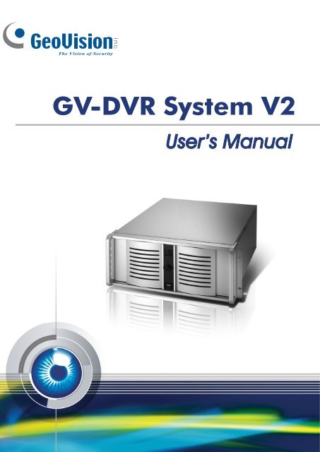
<strong>GV</strong>-<strong>DVR</strong> <strong>System</strong> <strong>V2</strong>User’s Manual
© 2008 GeoVision, Inc. All rights reserved.Under the copyright laws, this manual may not be copied, in whole or in part, without the writtenconsent of GeoVision.Every effort has been made to ensure that the information in this manual is accurate. GeoVision is notresponsible for printing or clerical errors.GeoVision, Inc.9F, No. 246, Sec. 1, Neihu Rd.,Neihu District, Taipei, TaiwanTel: 886-2-8797-8377http://www.geovision.com.twThe Windows XP Embedded is the componentized version of Microsoft Windows XP Professional,forsaking much functionality that Windows XP Professional provides and meeting the specificrequirements of <strong>GV</strong>-Hot Swap <strong>DVR</strong> <strong>System</strong> <strong>V2</strong>. For details on embedded operation systems, pleasevisit Microsoft's website.Trademarks used in this manual: GeoVision, the GeoVision logo, <strong>GV</strong>-Hot Swap <strong>DVR</strong> <strong>System</strong> <strong>V2</strong>, and<strong>GV</strong> series products are trademarks of GeoVision, Inc. Windows and Windows XP are registeredtrademarks of Microsoft Corporation. Other company and product names mentioned herein aretrademarks of their respective companies. GeoVision assumes no responsibility with regard to theperformance or use of these products.January 2008
User’s Manual for <strong>GV</strong>-<strong>DVR</strong> <strong>System</strong> <strong>V2</strong>Welcome to the <strong>GV</strong>-<strong>DVR</strong> <strong>System</strong> <strong>V2</strong> User’s Manual.The Manual provides an overview of the <strong>GV</strong>-<strong>DVR</strong> <strong>System</strong> <strong>V2</strong> and its accessories. It alsoincludes the instructions to guide you through the installation and use of the <strong>GV</strong>-<strong>DVR</strong> <strong>System</strong><strong>V2</strong>:• Chapter 1, IntroductionIdentifies the <strong>GV</strong>-<strong>DVR</strong> <strong>V2</strong>’s accessories and options.• Chapter 2, OverviewIdentifies the <strong>GV</strong>-<strong>DVR</strong> <strong>V2</strong>’s components.• Chapter 3, Getting StartedProvides step-by-step instructions on setting up the <strong>GV</strong>-<strong>DVR</strong> <strong>V2</strong>.• Chapter 4, <strong>DVR</strong> Health AnalysisIntroduces how to collect data to obtain the service of <strong>DVR</strong> health analysisfrom GeoVision.• Chapter 5, TroubleshootingSuggests courses of action if the <strong>GV</strong>-<strong>DVR</strong> <strong>V2</strong> doesn’t seem to be working properly.The instructions and figures in this manual are based on <strong>GV</strong>-<strong>System</strong> version 8.2.
Regulatory NoticesFCC NoticeThis equipment has been tested and found to comply with the limits for a Class A digital device,pursuant to part 15 of the FCC Rules. These limits are designed to provide reasonable protectionagainst harmful interference when the equipment is operated in a commercial environment.Class AThis equipment generates, uses, and can radiate radio frequency energy and, if not installed and usedin accordance with the instruction manual, may cause harmful interference to radio communications.Operation of this equipment in a residential area is likely to cause harmful interference in which casethe user will be required to correct the interference at their own expense.CE NoticeThis is a Class A product. In a domestic environment, this product may cause radio interference inwhich case the user may be required to take adequate measures.RoHS ComplianceThe Restriction of Hazardous Substances (RoHS) Directive is to forbid the use of hazardous materialsof production. To meet the RoHS Directive requirements, this product is made to be RoHS compliant.WEEE ComplianceThis product is subject to the Waste Electrical and Electronic Equipment (WEEE) Directive and madecompliant with the WEEE requirements.4
Safety InstructionsObserve these safety instructions to help ensure against injury to yourself and damage to theproduct.• Read all safety and installation instructions before you operate the product.• Do not operate the product in high humidity areas or expose it to water or moisture.• Do not put the product in an unstable, a slanting or vibrated place.• Do not block any ventilation opening.• Do not install the product near any heat sources such as radiator, heat register or otherapparatus that produce heat.• Operate the product using only the type of power source indicated on the marking label.• Do not defeat the safety purpose of the grounding-type plug. A grounding plug has two bladesand a third grounding prong. The third prong is provided for your safety. If the provided plug doesnot fit into your outlet, consult an electrician for replacement of the obsolete outlet.• Do not overload wall outlets or extension cords, as this may cause fire or electric shock.• Do not use the product when abnormality occurs, such as emitting smoke from the product,smelling burning, being damaged by drop, invasion of foreign objects inside the product, etc. Bealways sure to remove the AC adaptor at once and contact your dealer.• Do not use accessories or attachments not recommended by the manufacturer, as they maycause hazards and void the warranty.• Do not attempt to service the product yourself, as removing the casing may expose you todangerous voltage and void the warranty.5
1.2 ModelsThe <strong>GV</strong>-<strong>DVR</strong> <strong>V2</strong> has the following models:<strong>GV</strong>-2016S <strong>V2</strong><strong>GV</strong>-2008S <strong>V2</strong><strong>GV</strong>-1480S <strong>V2</strong><strong>GV</strong>-1240S <strong>V2</strong><strong>GV</strong>-1120S <strong>V2</strong>- Sixteen-channel digital video recorder- Records up to 480 (NTSC) / 400 (PAL) fps at the D1 resolution- Has the option of 1600GB, 2000GB and 3000GB internal storage- Eight-channel digital video recorder- Records up to 240 (NTSC) / 200 (PAL) fps at the D1 resolution- Has the option of 1200GB, 1600GB and 2000GB internal storage- Sixteen-channel digital video recorder- Records up to 480 (NTSC) / 400 (PAL) fps at the CIF resolution- Has the option of 900GB, 1200GB and 1600GB internal storage- Eight-channel or sixteen-channel digital video recorder- Records up to 240 (NTSC) / 200 (PAL) fps at the CIF resolution- Has the option of 600GB, 1200GB and 1600GB internal storage- Sixteen-channel digital video recorder- Records up to 120 (NTSC) / 100 (PAL) fps at the CIF resolution- Has the option of 300GB, 600GB and 1200GB internal storage8
1Introduction1.3 OptionsOptional devices can expand your <strong>GV</strong>-<strong>DVR</strong> <strong>V2</strong>’s capabilities and versatility. Contact your dealer formore information.<strong>GV</strong>-Video Loop Through This card can take the video signal from the <strong>GV</strong>-<strong>DVR</strong> <strong>V2</strong> and thenCardsplit it into 16 signals while maintaining video quality. It can meet theneed for multiple spot monitors.<strong>GV</strong>-IO 12-In CardWith 12-point digital inputs, this card can expand the <strong>GV</strong>-<strong>DVR</strong> <strong>V2</strong> upto 16 sensor inputs.<strong>GV</strong>-IO 12-Out CardWith 12-point relay outputs, this card can expand the <strong>GV</strong>-<strong>DVR</strong> <strong>V2</strong> upto 16 alarm outputs.<strong>GV</strong>-Multi Quad CardWith this card, the <strong>GV</strong>-<strong>DVR</strong> <strong>V2</strong> can connect up to 5 TV screens. Thescreen divisions on the TV screens can be definable.<strong>GV</strong>-Data Capture V3 Series <strong>GV</strong>-Data Capture V3 can integrate the <strong>GV</strong>-<strong>DVR</strong> <strong>V2</strong> to an electronicPOS system, while <strong>GV</strong>-Data Capture V3E can establish suchintegration through LAN or Internet.<strong>GV</strong>-I/O USB Box<strong>GV</strong>-I/O USB Box provides 16 inputs and 16 relay outputs, and up to9 <strong>GV</strong>-I/O USB Boxes can chain together to expand the use.However, 16 inputs are only supported when it is used with<strong>GV</strong>-<strong>System</strong> version 8.2 or later.<strong>GV</strong>-Hub Box An easy way for serial port extension. This hub can add 4RS-232/RS-485 serial ports through the <strong>GV</strong>-<strong>DVR</strong> <strong>V2</strong>’s USB port.<strong>GV</strong>-COM BoxThis unit can add 1 RS-232/RS-485 serial port through the <strong>GV</strong>-<strong>DVR</strong><strong>V2</strong>’s USB port.<strong>GV</strong>-Joystick<strong>GV</strong>-Joystick facilitates the PTZ camera control. It can be eitherplugged into the <strong>GV</strong>-<strong>DVR</strong> <strong>V2</strong> for independent use or connected to<strong>GV</strong>-Keyboard to empower the operation. However, this device canonly work on <strong>GV</strong>-<strong>System</strong> version 8.2 or later.VGA CardWith the VGA card, the dual display for monitoring and playback ismade possible.RAMMultiple options for the amount of RAM are available to meet differentneeds.Hard DiskMultiple options for the HDD capacity are available to meet differentneeds.<strong>GV</strong>-DOM (Disk on Module) <strong>GV</strong>-DOM, a solid-state hard drive, is used for operating system andsystem software to get higher performance under harsh conditions.Note: The purchased <strong>GV</strong>-series cards will be added on the <strong>GV</strong>-<strong>DVR</strong> <strong>V2</strong> before shipment.9
Chapter 2 Overview2.1 Front View1 2 3 498765Figure 11 5.25” Hard Disk Compartment 6 Power Switch2 Power LED 7 Reset Button3 Hard Drive Activity LED 8 Key Lock4 DVD ± RW Drive 9 USB Port x 25 Fan x 210
2Overview2.2 Rear ViewFigure 21 RS-485 ± for PTZ Control 10 USB Port x 42 RJ-11 Port 11 VGA Monitor Port3 D-Type Audio Port x 2 12 LPT Parallel Printer Port4 BNC Connector x 16 13 DB-9 Serial Input5 RCA TV Output 14 PS/2 Mouse Input6 Audio Microphone In Port 15 PS/2 Keyboard Input7 Audio Line In Port 16 AC Power Switch8 Audio Line Out Port 17 AC Power Input (Full Range)9 Ethernet Port x 211
Chapter 3 Getting Started3.1 Basic InstallationBasic installation describes all the equipments required to program and operate the <strong>GV</strong>-<strong>DVR</strong> <strong>V2</strong>.Figure 31. Using the supplied power cord, connect one end to the AC input and the other end to the poweroutlet.2. Connect the keyboard to the PS/2 input.3. Connect the mouse to the PS/2 input.4. Using the VGA cable supplied by the monitor manufacturer, connect the VGA monitor.5. For video lost beep, connect Speakers to the Audio Line Out port.6. Using the RJ-45 cable, connect one end to the Ethernet port and the other end to Network.7. Using the BNC video cables, connect one end to the BNC connectors and the other end to videosources.8. Using the supplied D-type audio cables, connect one end to the audio ports and the other end toaudio sources.Note: The monitor you use must be capable of having a screen resolution of 1280 x 1024 and displaycolor of 32 bits.12
3Getting Started3.2 Turning on the PowerOnce the above hardware is properly connected, it is the time to turn on the <strong>GV</strong>-<strong>DVR</strong> <strong>V2</strong>. To turn on thepower, follow these steps:1. Turn on the monitor.OnFigure 42. Turn on the AC power switch on the rear panel.Power OnFigure 53. Turn on the main power switch on the front panel.Power OnFigure 6The <strong>GV</strong>-<strong>DVR</strong> <strong>V2</strong> will run a series of self-tests. After two or three minutes, a series of messages may bedisplayed as the various hardware and software subsystems are activated. After this finishes, the<strong>GV</strong>-<strong>System</strong> Software (Multicam Surveillance <strong>System</strong>) should load automatically and bring you to themain screen with 8 or 16 cameras display.13
3.3 Configuring an IP AddressThe purpose of configuring an IP address is to support the remote monitoring, control and configurationof the <strong>GV</strong>-<strong>DVR</strong> <strong>V2</strong> over a network connection.The <strong>GV</strong>-<strong>DVR</strong> <strong>V2</strong> is enabled for DHCP network. An IP address will be automatically allocated when the<strong>GV</strong>-<strong>DVR</strong> <strong>V2</strong> is powered up. Despite the DHCP setting, it is recommended that a static IP address beconfigured on the unit.The <strong>GV</strong>-<strong>DVR</strong> <strong>V2</strong> uses Windows operating system to configure an IP address. For this, you must exit toWindows.Note: Exiting to the Windows operating system is a protected feature. The default ID and Password is“0000”.Exit to Windows1. Exit the main screen to display the <strong>GV</strong>-Desktop screen.Figure 7 Exit the main screen2. Click the Settings button, and enter the valid ID and Password to display the Settings dialog box.3. Under Desktop Type, select Windows from the drop-down list, and click OK.4. Click the Log Off button, and enter the valid ID and Password to display the Windows desktop.14
3Getting Started5. Configure a static IP address on the Windows XP platform. Check your network administrator if youhave questions about the configuration.2 43Figure 8 The <strong>GV</strong>-DesktopBack to <strong>GV</strong>-DesktopClick the Windows Start button, point to Programs, select <strong>GV</strong>Combo, and click Key Lock Utility.Figure 9 Windows XP desktop15
3.4 Extended InstallationBeyond basic installation, the <strong>GV</strong>-<strong>DVR</strong> <strong>V2</strong> package provides the following accessories to make yourunit even more powerful and convenient:• <strong>GV</strong>-Keyboard• IR-Remote Control• RJ-11 to DB9 Cable for PTZ control<strong>GV</strong>-KeyboardThe <strong>GV</strong>-Keyboard is designed to operate the <strong>GV</strong>-<strong>DVR</strong> <strong>V2</strong> exclusively. Using the USB cable suppliedwith the <strong>GV</strong>-Keyboard, plug one end into the <strong>GV</strong>-Keyboard and the other end into the assigned USBport (COM3) on the front of the <strong>GV</strong>-<strong>DVR</strong> <strong>V2</strong>; you can operate the Keyboard immediately withoutinstalling any drivers.For details on the <strong>GV</strong>-Keyboard, find the Installation Manual included in its own package.Figure 10It is also possible to plug the Keyboard into other USB ports of the <strong>GV</strong>-<strong>DVR</strong> <strong>V2</strong>. For this, you mustmodify the default COM port on the Multicam Controller pop-up once the Keyboard is connected. SeeFigure 11-1.16
3Getting StartedTo modify the default COM port:1. Click to stop the Keyboard service first.2. In the Port 1 field, modify the port number from the drop-down list. For the port allocation, refer toFigure 11-2.3. Click to start the service.1USB & COM Ports Allocation on<strong>GV</strong>-<strong>DVR</strong> <strong>V2</strong>2Front PanelCOM3USBUSBCOM4Rear PanelCOM5 COM7USB USBUSB USBCOM6 COM8Figure 11-1 Figure 11-2IR Remote ControlThe IR Remote Control is another plug-and-play device. Simply plug the Receiver into any USB ports ofthe <strong>GV</strong>-<strong>DVR</strong> <strong>V2</strong>.For details on the IR Remote Control, find the User’s Manual included in its own package.Figure 1217
I/O DevicesThe <strong>GV</strong>-<strong>DVR</strong> <strong>V2</strong>, with built-in <strong>GV</strong>-NET/IO Card, provides 4 alarm outputs and 4 sensor inputs.Relay Output 1~4ComSensor Input 1~4GroundFigure 13PTZ DomesWhen connecting PTZ domes, you need to plug the supplied RJ-11 to DB9 cable into the DB9 port ofthe <strong>GV</strong>-<strong>DVR</strong> <strong>V2</strong>.PTZ Dome 1PTZ Dome 2PTZ Dome 16RS-485+RS-485-Connects to theDB9 port of the<strong>GV</strong>-<strong>DVR</strong> <strong>V2</strong>RJ-11 to DB9 CableDB9 PortFigure 1418
3Getting Started3.5 Recovery DVDIf preinstalled files are damaged, use the supplied Recovery DVD to restore them. To restore theoperation system and all preinstalled software, follow these steps:Note: After recovery, you need to re-install all settings and passwords. But the recovery will not deleteyour recording files saved in the <strong>GV</strong>-<strong>DVR</strong> <strong>V2</strong> since it only reformats the partition C and all of your filesare still stored at other partitions.1. Insert the Recovery DVD, and restart the <strong>GV</strong>-<strong>DVR</strong> <strong>V2</strong>.2. The message “Are you sure want to recover C partition?” will appear. Click Yes.Figure 153. When the recovery is complete, the message “Operation completed. Please take outdisks from DVD-ROM” will appear. Click Yes, and remove the DVD.Figure 1619
Configuring the <strong>GV</strong>-<strong>DVR</strong> <strong>V2</strong> for PAL after RecoveryThe default video standard of the Recovery DVD is set to NTSC. If the video standard in your country isPAL, remember to configure the <strong>GV</strong>-<strong>DVR</strong> <strong>V2</strong> for PAL after using the Recovery DVD.1. Click the Configure button, point to A/V Setting, and then select Video Source.Figure 172. In the Video Standard field, select PAL from the drop-down list, and click OK.Figure 1820
3Getting Started3.6 Updating <strong>GV</strong>-<strong>DVR</strong> <strong>System</strong> <strong>V2</strong>GeoVision will periodically release the updated Recovery DVD including the latest <strong>GV</strong>-<strong>System</strong> Software(Multicam Surveillance <strong>System</strong>) and Windows updates. If you like to update your <strong>GV</strong>-<strong>DVR</strong> <strong>System</strong> <strong>V2</strong>,contact your dealer to get one.Before contacting your dealer, you may check software update news at our website:http://www.geovision.com.tw21
Chapter 4 <strong>DVR</strong> Health AnalysisGeoVision offers health analysis to the <strong>GV</strong>-<strong>DVR</strong> <strong>V2</strong>. The service is intended to give diagnosis for earlyand immediate detection of problems.It is recommended to have the health analysis during the first week after you install the <strong>GV</strong>-<strong>DVR</strong> <strong>V2</strong>,and then have the checkup every three months. It will take 5 working days for response.Please prepare the following data for analysis, and send to dvrsystem@geovision.com.tw• <strong>System</strong> Settings• <strong>System</strong> Log• Information of your computer system (Processor; Drives; Voltage, Temperature and Fans)4.1 <strong>System</strong> SettingsPlease back up your system configurations using the Fast Backup and Restore application.1. Run Fast Backup & Restore Main <strong>System</strong> from the Start menu.Figure 1922
4<strong>DVR</strong> Health Analysis2. Select Backup <strong>System</strong> Settings. This dialog box appears.Figure 203. Press the Next Step button to back up all your system settings. The Save As dialog boxappears.4. Select the destination drive to store the backup file. When the backup is complete, this messagewill appear: Successfully Backup MultiCam <strong>System</strong> Settings.23
4.2 <strong>System</strong> LogPlease provide the sys*.mdb files of system log. The files by default are saved at D:\Log\database. Ifyou have modified the default location, you can check the path by the following steps:1. Click the Configure button on the main system, point to General Setting, and then select <strong>System</strong>Log Setting. This dialog box appears.Figure 212. Click Set Location. You should see the location of your system log.Figure 2224
4<strong>DVR</strong> Health Analysis4.3 Information of Your Computer <strong>System</strong>To get the information of your computer system, please follow the steps below to install the freesoftware PC WIZARD. By using the software, the computer information can be easily collected andsaved for analysis:• Processor: includes Type, Frequency, Data Cache L1, Trace Cache L1, Cache L2, Voltage,Processor Temperature, FPU Coprocessor.• Drives: includes Number of Hard Disk, Number of Drive, Total Size and Free Space of Drive.• Voltage, Temperature and Fans: includes Monitoring Chip, Voltage CPU, Chassis Fan, ProcessorTemperature, Mainboard Temperature, Hard Disk Temperature.1. Download and install PC WIZARD from http://www.cpuid.com/pcwizard.php .2. After installation, run the program.3. Right-click the Processor icon , and click Save as.Figure 2325
4. In the Save As dialog box, select Format HTML and click OK.Figure 245. Select the Save location, type the file name, and then click Save to save the Processor informationas HTML file.6. Repeat Steps 3-5 to save the Drives information as HTML file.7. To save the Voltage, Temperature and Fans information , please follow these steps:A. Click the Voltage, Temperature and Fans icon. The related data is displayed at the rightwindow.B. Click the first item Monitoring Chip.C. Click Edit on the menu bar and click Select All to highlight all the contents.D. Click Edit on the menu bar and select Copy.E. Open a Notepad. Paste and save the information to TXT file.26
4<strong>DVR</strong> Health Analysis4.4 Health Analysis FormPlease send the related data for analysis along with this Health Analysis Form todvrsystem@geovision.com.tw.Health Analysis of <strong>GV</strong>-<strong>DVR</strong> <strong>V2</strong>Contact Person:Title:Company Name:Telephone: (O)(H)Fax:E-Mail:Model:Bar Code:4.5 Check ListRead this check list before submitting the health analysis request:• <strong>System</strong> Settings- EXE file• <strong>System</strong> Log- sys*.mdb• Computer <strong>System</strong>- Processor information of HTML file• Computer <strong>System</strong>- Drives information of HTML file• Computer <strong>System</strong>- Voltage, Temperature and Fans information of TXT file• Health Analysis Form27
Chapter 5 Troubleshooting<strong>GV</strong>-<strong>DVR</strong> <strong>System</strong> <strong>V2</strong> is designed for durability. However, should problems occur, following theprocedures here can help determine the cause.A portable 2.5'' HDD connected to the <strong>GV</strong>-<strong>DVR</strong> <strong>V2</strong> front panel cannot bedetected.When the portable 2.5” HDD connected to a <strong>GV</strong>-<strong>DVR</strong> <strong>V2</strong> cannot be detected, try this step:Use a dual head USB cable and insert both heads to the USB ports on the <strong>GV</strong>-<strong>DVR</strong> <strong>V2</strong> front panel asillustrated below.Figure 2528
5TroubleshootingThe Main <strong>System</strong> cannot be minimized, and the <strong>GV</strong>-Desktop toolbar fails toappear.When the <strong>GV</strong>-<strong>DVR</strong> <strong>V2</strong> is set up in a LAN where its router or server cannot assign the IP addressesthrough DHCP, the Main <strong>System</strong> may not be minimized, and the <strong>GV</strong>-Desktop toolbar may fail to appear.Try these steps:1. Manually assign the fixed IP address to the <strong>GV</strong>-<strong>DVR</strong> <strong>V2</strong>.A. Unplug the Ethernet cable, and restart the <strong>GV</strong>-<strong>DVR</strong> <strong>V2</strong>.B. Go to the <strong>GV</strong>-Desktop, click the Programs button, and then select Disk Management.Figure 26C. Right-click <strong>System</strong> (C:), and select Explore.Figure 2729
D. Select Network Connections, right-click Local Area Connection, and then selectProperties.Figure 28E. In the Local Area Connection Properties dialog box, select Internet Protocol (TCP/IP) andthen click Properties.Figure 2930
5TroubleshootingF. Select Use the following IP address, and type the IP info in the fields.Figure 302. Replace the router or server that can assign the IP addresses through DHCP in a LAN.<strong>GV</strong>-<strong>DVR</strong> <strong>V2</strong> won’t turn on.If your <strong>GV</strong>-<strong>DVR</strong> <strong>V2</strong> won’t turn on or you don't hear a startup sound or any fan or drive noise, try thesesteps:1. Make sure that you switch on the AC power on the rear panel.OffOnFigure 312. Make sure that the power cord is properly connected to both the <strong>GV</strong>-<strong>DVR</strong> <strong>V2</strong> and power outlet. Ifyou are using a power strip, make sure that the strip is powered on.3. If the problem persists, consult your dealer.31
<strong>GV</strong>-<strong>DVR</strong> <strong>V2</strong> stops responding (aka “crashed” or froze”).If your <strong>GV</strong>-<strong>DVR</strong> <strong>V2</strong> is not responding to your clicking, typing, or mouse movements, try these steps toget your <strong>GV</strong>-<strong>DVR</strong> <strong>V2</strong> back on track. Please note that you will lose any unsaved changes in all openapplications.1. Restart your <strong>GV</strong>-<strong>DVR</strong> <strong>V2</strong> by pressing the Reset button on the front panel.2. If your <strong>GV</strong>-<strong>DVR</strong> <strong>V2</strong> is still unresponsive, switch off the Power button to shut it down. Wait 30seconds and then restart your <strong>GV</strong>-<strong>DVR</strong> <strong>V2</strong>.ResetPower On/OffFigure 32<strong>GV</strong>-<strong>DVR</strong> <strong>V2</strong>’s hard disk corrupts.If you are experiencing file system corruption problems, such as lost clusters, cross-linked files orinvalid files or directories, try these steps:1. Use Windows built-in utility to scan your hard disk for errors and attempt to fix them.Follow these steps:A. On the <strong>GV</strong>-Desktop, click the Programs button, and select Disk Management. See Figure 26.B. Right-click the desired hard disk and select Properties from the file menu to display theProperties window.Figure 3332
5TroubleshootingC. Click the Tools tab in the upper portion of the window.D. Under Error-checking, click the Check Now button.Figure 34E. Select Automatically fix file system errors and Scan for and attempt recovery of badsectors.F. Click Start.Figure 352. If the Windows hard disk utility still cannot fix the problem in Partition C, try rebuilding the operationsystem and <strong>GV</strong>-<strong>System</strong> Software by using the Recovery DVD. Refer to 3.5 Recovery DVD.3. If the problem persists, replace a hard disk drive.<strong>GV</strong>-<strong>DVR</strong> <strong>V2</strong> suffers virus attack.<strong>GV</strong>-<strong>DVR</strong> <strong>V2</strong> is designed and optimized for Windows XP platform. It may be vulnerable to newly createdworms and exploits that attack any of the underlying operating system’s previously undocumentedflaws. If your <strong>GV</strong>-<strong>DVR</strong> <strong>V2</strong> suffers virus attack, try rebuilding the operation system and <strong>GV</strong>-<strong>System</strong>Software by using the Recovery DVD. Refer to 3.5 Recovery DVD.33
<strong>GV</strong>-<strong>DVR</strong> <strong>V2</strong> has video and/or audio lost.If your <strong>GV</strong>-<strong>DVR</strong> <strong>V2</strong> fails to show video, audio or both, try these steps:1. Check the video/audio connection. Make sure one end of the D-type video/audio cable is securelyconnected to the video/audio device, and the other end to the video/audio port of the <strong>GV</strong>-<strong>DVR</strong> <strong>V2</strong>.2. Make sure the video/audio device is turned on.3. Switch the cable from the functional channel to the non-functional channel, and vice versa. If thepreviously non-functional channel is now able to deliver video/audio, you should check thevideo/audio device itself and its related cables.The screen image appears distorted or jitters.If the screen image seems to be distorted, jitter, or not to look right, try these steps:1. Make sure the video standard in your country matches the setting in the <strong>GV</strong>-<strong>DVR</strong> <strong>V2</strong>. Refer toConfiguring the <strong>GV</strong>-<strong>DVR</strong> <strong>V2</strong> for PAL after Recovery in 3.5 Recovery DVD.2. Make sure the camera and its cable are not damaged or frayed. Try to replace a camera or cameracable to see if this fixes the problem.How can I find more help?1. Visit our website at http://www.geovision.com.tw/english/4_1.asp2. Write us at dvrsystem@geovision.com.tw34
SpecificationsSpecifications<strong>System</strong>Model <strong>GV</strong>-2016S <strong>V2</strong> <strong>GV</strong>-2008S <strong>V2</strong> <strong>GV</strong>-1480S <strong>V2</strong> <strong>GV</strong>-1240S <strong>V2</strong> <strong>GV</strong>-1120S <strong>V2</strong>CPURAMHDD1600 GB 1200 GB 900 GB 600 GB 300 GB2000 GB 1600 GB 1200 GB 1200 GB 600 GB3000 GB 2000 GB 1600 GB 1600 GB 1200 GBOSMicrosoft Windows XP EmbeddedVGA Intel GMA 3000DirectX 9.0cDVD (±) RW 20XFanFront: 3 fansPower450 W, 110-230 V, 60-50 HzNote: Multiple options for the HDD capacity, amount of RAM and type of VGA are available to meetdifferent needs. Please contact your dealer or sales representative for further information.VideoIntel Pentium Core 2 Duo Processor2 GBDual Channel1 GBDual Channel1 GBDual ChannelModel <strong>GV</strong>-2016S <strong>V2</strong> <strong>GV</strong>-2008S <strong>V2</strong> <strong>GV</strong>-1480S <strong>V2</strong> <strong>GV</strong>-1240S <strong>V2</strong> <strong>GV</strong>-1120S <strong>V2</strong>Video StandardNTSC, PALVideo Input16channels8channels16channels8 / 16channelsImage ControlContrast / Brightness / Saturation / HueNote: The functions with star marks*are only available on <strong>GV</strong>-<strong>System</strong> version 8.2.16channelsInput Level1.0 Vp-p (± 10%) composite, 75 ΩTV Output1.0 Vp-p compositeVideo Loop Output(Optional)16channels8channels16channels8 / 16channels16channelsCompressionH/W: MPEG-2 /MPEG-4 (ASP)S/W: Geo MPEG4 / GeoMpeg4 (ASP) / Geo H264Geo MPEG4 / Geo Mpeg4 (ASP) /Geo H264 / Geo H264 <strong>V2</strong>*Geo H264 <strong>V2</strong>*Display Frame NTSC 480 FPS 240 FPS 480 FPS(Max) PAL 400 FPS 200 FPS 400 FPSDisplayResolutionCamera NameNTSCPALScreen Split ControlScreen Rotate Control360 x 240 /720 x 480 /720 x 480 De-interlace360 x 288 /720 x 576 /720 x 576 De-interlaceMax. 32 characters320 x 240 / 360 x 240* /640 x 480 / 640 x 480 De-interlace /720 x 480 / 720 x 480 De-interlace320 x 240 / 360 x 288* /640 x 480 / 640 x 480 De-interlace /720 x 576 / 720 x 576 De-interlace1x1 / 2x2 / 1+5 / 1+7 / 3x3 / 2+8 / 1+12 / 1+16 / 4x41 ~ 10 sec.35
AudioModel <strong>GV</strong>-2016S <strong>V2</strong> <strong>GV</strong>-2008S <strong>V2</strong> <strong>GV</strong>-1480S <strong>V2</strong> <strong>GV</strong>-1240S <strong>V2</strong> <strong>GV</strong>-1120S <strong>V2</strong>Audio InputInput Level16channels8channels0.5 ~ 1 Vp-p compositeCompression ADPCM / G.72316channels8 / 16channels16channelsRecordingModel <strong>GV</strong>-2016S <strong>V2</strong> <strong>GV</strong>-2008S <strong>V2</strong> <strong>GV</strong>-1480S <strong>V2</strong> <strong>GV</strong>-1240S <strong>V2</strong> <strong>GV</strong>-1120S <strong>V2</strong>Recording FrameImageCompressionDimensionsRecording ModeScheduleInstant PlaybackPre RecordingNTSCPALNTSCPALH/W:480 (D1)H/W:400 (D1)H/W:240 (D1)H/W:200 (D1)720 x 480 /720 x 480 De-interlace720 x 576 /720 x 576 De-interlaceS/W:480 (CIF)S/W:400 (CIF)S/W:240 (CIF)S/W:200 (CIF)S/W:120 (CIF)S/W:100 (CIF)320 x 240 / 360 x 240* /640 x 480 / 640 x 480 De-interlace /720 x 480 / 720 x 480 De-interlace320 x 240 / 360 x 288* /640 x 480 / 640 x 480 De-interlace /720 x 576 / 720 x 576 De-interlace /Round the Clock / Motion Detection / Sensor Detection /Pre & Post Recording / Schedule Recording96 groups per day by 15 min.10 sec. / 30 sec. / 1 min. / 5 min.1~ 90 sec. (1 FPS)Water MarkingSupportNote: The functions with star marks*are only available on <strong>GV</strong>-<strong>System</strong> version 8.2.Searching and PlaybackSearch MethodDate / Time / Event SearchLog SearchBackup TypeDate / TimeSelectable on the tree list and calendarThrough the log data to find the video event / timeDVD+R (DL) / DVD-R (DL) / DVD+R / DVD+RW / DVD-R /DVD-RW / CD-R / CD-RW36
SpecificationsRemote Client SoftwareMonitoringEnvironmentWebCam Live ViewWebCam / Twin Server / Center<strong>V2</strong> / VSM / Control Center /Remote Playback Server / Remote View / IP Multicast /<strong>GV</strong>iew <strong>V2</strong> for PDA / MSView <strong>V2</strong> for Windows Mobile 5.0 / MSView V3for Windows Mobile 6.0*/ SSView <strong>V2</strong> for Symbian Smartphone /SSView V3 for Nokia S60 2nd and 3rd / 3G Mobile PhoneMax. 16 channels transmission(Max. 200 channels accessible)Remote Search WebCam’s Remote Playback / Remote Playback ServerNote: The functions with star marks*are only available on <strong>GV</strong>-<strong>System</strong> version 8.2.<strong>System</strong> Monitoring and RecoveryPower Restoration Power restored after AC power lossMonitoringRecovery DVDTwo independent Watchdogs(Hardware Watchdog + Software Watchdog)Automatic system rebuildAlarmSensor InputAlarm OutputMotion DetectionStandard<strong>GV</strong>-IO 12-In Card (Optional)<strong>GV</strong>-IOUSB Box(Optional)Standard<strong>GV</strong>-IO 12-Out Card (Optional)<strong>GV</strong>-IOUSB Box(Optional)16 channels4 inputs16 inputs8 ~ 72 inputs16 ~ 144 inputs (only with <strong>GV</strong>-<strong>System</strong>version 8.2 or later)4 outputs16 outputs16 ~ 144 outputsConnectorVideo InputBNC 8 / 16 portsVideo Loop Output(Optional)BNC 16 portsAudio InputRCA 8 / 16 portsAudio Microphone In Mini stereo jackAudio OutputMini stereo jackTV OutputRCARS±485 for PTZ Control 2-pin terminalEthernet RJ-45, 10/100/1000 Mbps x 2USB 2.0Front: 2 ports, Rear: 4 portsVGA Output15-pin female D SubRemote AccessTCP/IP37
EnvironmentOperating Temp.Humidity0 ~ 50 °C (32 ~ 122 °F)0 ~ 80% RH (non-condensing)PhysicalModel <strong>GV</strong>-2016S <strong>V2</strong> <strong>GV</strong>-2008S <strong>V2</strong> <strong>GV</strong>-1480S <strong>V2</strong> <strong>GV</strong>-1240S <strong>V2</strong> <strong>GV</strong>-1120S <strong>V2</strong>IPC Case4U RackmountColorSilverDimensions 483 (W) x 178 (H) x 528 (D) mm (19 x 7 x 21 inch)300GB17 Kg600GB 17.6 Kg 17.6 KgWeight900GB18.2Kg1200GB 18.9 Kg 18.8 Kg 18.8 Kg 18.8 Kg1600GB 19.2 Kg 19 Kg 18.9 Kg 18.9 Kg2000GB 19.3 Kg 19.1 Kg3000GB 19.5 KgLanguageTypeEnglish / Czech / French / German / Hebrew / Hungarian / Italian /Japanese / Polish / Portuguese (Brazil) / Russian / Spanish /Simplified Chinese / Traditional ChineseProduct design and specifications are subject to change without notice.38
Warranty PolicyWarranty PolicyWarranty CoverageGeoVision, Inc. warrants <strong>GV</strong>-<strong>DVR</strong> <strong>System</strong> <strong>V2</strong>, IR Remote Control, and <strong>GV</strong>-Keyboard against defectsin materials and workmanship for a period of TWO (2) years from the date of purchase.Other packaged accessories and software (including but not limited to <strong>System</strong> Software) areexcluded.If a defect where due to causes attributable to GeoVision arises and a valid claim is received byGeoVision within the Limited Warranty Period, at its option, GeoVision will (1) repair the product at nocharge, using new or refurbished replacement parts, or (2) exchange the product with a product that isnew or which has been manufactured from new or serviceable used parts and is at least functionallyequivalent to the original product.GeoVision warrants replacement parts or repairs for thirty (30) days from the date of GeoVisionshipment or for the remainder of the Limited Warranty Period, whichever provides longer coverage foryou. When a product or part is exchanged, any replacement item becomes your property and thereplaced item becomes GeoVision’s property.Exclusions and LimitationsThe Customer shall have no coverage or benefits under this Limited Warranty if any of the followingconditions are applicable:1. The product has been subjected to abnormal use, failure to follow the instructions prescribed inUser’s Manuals, improper storage, improper packaging, improper maintenance, unauthorizedmodifications, unauthorized repair, misuse, neglect, abuse, accident, alternation, improperhardware/software installations, or other acts due to causes not attributable to GeoVision, includingdamage caused by shipping.2. The product was not purchased from an authorized distributor or agent.3. The product has been damaged from exposure to rain, flood, storm, moisture, dampness, weatherconditions, an Act of God, force majeure, improper use of any electrical source, or the connectionto other products not recommended for interconnection by GeoVision.4. Defects or damage caused due to virus attack.5. The product bar code on the system case has been removed, defaced or altered.6. The system case has been opened.39
THIS WARRANTY IS IN LIEU OF ALL OTHER WARRANTIES, WHETHER ORAL ORWRITTEN, EXPRESS OR IMPLIED. THE WARRANTY IS LIMITED TO REPAIR OREXCHANGE THE PRODUCT AT GEOVISION’S OPTION. OTHER EXPRESSED ORIMPLIED WARRANTIES FOR THIS PRODUCT, INCLUDING THE IMPLIED WARRANTIESOF MERCHANTABILITY AND FITNESS FOR A PARTICULAR PURPOSE AREEXCLUDED IN DURATION TO THE WARRANTY PERIOD. NO WARRANTIESEXPRESSED OR IMPLIED WILL APPLY AFTER THIS PERIOD. GEOVISION SHALL NOTBE LIABLE FOR SPECIAL, DIRECT, INDIRECT, CONSEQUENTIAL DAMAGES.GEOVISION SHALL NOT BE LIABLE FOR LOST PROFITS, LOST OF DATA, PROGRAMSOR OTHER INFORMATION, DAMAGE TO OTHER PROPERTY CAUSED BY ANYDEFECTS OF THIS PRODUCT, OR DAMAGES BASED UPON INCONVENIENCE, LOSSOF PRODUCT USE, LOSS OF TIME, COMMERCIAL USE, INCIDENTAL AND/ORCONSEQUENTIAL DAMAGES FOR THE BREACH OF ANY EXPRESSED OR IMPLIEDWARRANTY, INCLUDING DAMAGES TO PROPERTY, AND TO THE EXTENT PERMITTEDBY LAW, DAMAGES FOR PERSONAL INJURY, OR OTHERWISE, EVEN IF GEOVISIONHAS BEEN ADVISED OF THE POSSIBILITIES OF SUCH DAMAGES.Warranty RequirementsTo validate your purchase, you shall complete the online Product Registration within 30 days from thedate of purchase at http://www.geovision.com.tw/english/4_6.asp. Or click GeoVision OnlineRegistration in My Favorite for a direct link.If you fail to complete the Product Registration, the warranty period will start from the date ofshipment.Before you return the productSome problems you experience may be related to software or the operating system. It is important toinvestigate other sources of assistance first. Before returning the product, try the following:1. Review troubleshooting sections in the documentation for software and peripheral devices.2. Try rebuilding the operation system and <strong>GV</strong>-<strong>System</strong> by using the Recovery DVD.3. Consult your dealer. They are your best sources for current information and support. Or you cancall or email GeoVision offshore offices for assistance.40
Warranty PolicyWhen you call or e-mail, please inform us the following:• Model name• Bar Code• Recovery DVD version• Details of the defect or problem• Attempted solutions• Your contact information• Reseller’s contact information4. If you find it is the software problem, please check our website or your dealer for software updates.Obtaining Warranty ServiceIf you are still unable to solve the problem and suspect that it is hardware related, follow these:1. Send an e-mail to GeoVision to start Return Merchandise Authorization (RMA) process.E-Mail: sales@geovision.com.tw or dvrsystem@geovision.com.tw2. Securely pack the product in its original carton using the original packing material, or in equivalentpackaging.3. The product shall be returned to GeoVision, Taiwan at your expense for shipping and insurancecosts.BEFORE YOU DELIVER YOUR <strong>GV</strong>-<strong>DVR</strong> SYSTEM <strong>V2</strong> FOR WARRANTY SERVICE, IT ISYOUR RESPONSIBILITY TO BACK UP YOUR DATA. YOU WILL BE RESPONSIBLE FORREINSTALLING ALL DATA, SETTINGS AND PASSWORDS. DATA RECOVERY IS NOTINCLUDED IN THE WARRANTY SERVICE AND GEOVISION IS NOT RESPONSIBLE FORDATA THAT MAY BE LOST OR DAMAGED DURING TRANSIT OR A REPAIR.41
Warranty FormWarranty FormThank you for purchasing the <strong>GV</strong>-<strong>DVR</strong> <strong>System</strong> <strong>V2</strong>. To help us validate your purchase and better serveyou in the future, please go to http://www.geovision.com.tw/english/4_6.asp or click GeoVision OnlineRegistration in My Favorite for a direct link to register online within 30 days from the date ofpurchase. Please keep this copy for your records.Name: First (given)Surname (family name)Company Name (only if the product is owned by company):Mailing Address:City/Town:Province/State:Country:Postal Code:Telephone: (O)Fax:E-Mail:Date of Purchase: (e.g. 16-APR-2007)Product:Please check the item you purchased.(H) <strong>GV</strong> – 2016S <strong>V2</strong> – 16 Port – 1600 GB <strong>GV</strong> – 2016S <strong>V2</strong> – 16 Port – 2000 GB <strong>GV</strong> – 2016S <strong>V2</strong> – 16 Port – 3000 GB <strong>GV</strong> – 2008S <strong>V2</strong> – 8 Port – 1200 GB <strong>GV</strong> – 2008S <strong>V2</strong> – 8 Port – 1600 GB <strong>GV</strong> – 2008S <strong>V2</strong> – 8 Port – 2000 GB <strong>GV</strong> – 1480S <strong>V2</strong> – 16 Port – 900 GB <strong>GV</strong> – 1480S <strong>V2</strong> – 16 Port – 1200 GB <strong>GV</strong> – 1480S <strong>V2</strong> – 16 Port – 1600 GB <strong>GV</strong> – 1240S <strong>V2</strong> – 16 Port – 600 GB <strong>GV</strong> – 1240S <strong>V2</strong> – 16 Port – 1200 GB <strong>GV</strong> – 1240S <strong>V2</strong> – 16 Port – 1600 GB <strong>GV</strong> – 1240S <strong>V2</strong> – 8 Port – 600 GB <strong>GV</strong> – 1240S <strong>V2</strong> – 8 Port – 1200 GB <strong>GV</strong> – 1240S <strong>V2</strong> – 8 Port – 1600 GB <strong>GV</strong> – 1120S <strong>V2</strong> – 16 Port – 300 GB <strong>GV</strong> – 1120S <strong>V2</strong> – 16 Port – 600 GB <strong>GV</strong> – 1120S <strong>V2</strong> – 16 Port – 1200 GB43
Bar Code:Shipment Date:GeoVision, Inc.9F, No. 246, Sec. 1, Neihu Rd.,Neihu District, Taipei, TaiwanTel: +886-2-8797-8377Fax: +886-2-8797-8335Email: sales@geovision.com.twdvrsystem@geovision.com.twhttp://www.geovision.com.tw44