
Create successful ePaper yourself
Turn your PDF publications into a flip-book with our unique Google optimized e-Paper software.
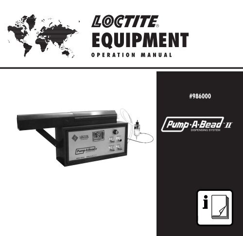
<strong>EQUIPMENT</strong>OPERATION MANUAL®#986000DISPENSING SYSTEM
ContentsSection Description Page No.1 Introduction ..............................................................................1Items Supplied ........................................................................2View of Pump-A-Bead II with components labeled ..............32 Theory of Operation ................................................................43 InstructionsSafety Precautions ..................................................................5Installation ..............................................................................6Explanation of Controls............................................................8OperationInitial Setup ............................................................................11Loading a Cartridge................................................................11Adjusting Product Flow Rate ..................................................12Low Level Indicator ................................................................13Shutdown Procedure..............................................................134 TroubleshootingGeneral ..................................................................................14Pump Replacement Procedure ..............................................16Spare Parts ............................................................................18Phone Numbers for Help........................................................185 Specifications:Dimensions ............................................................................19Weights..................................................................................20Utilities Required ....................................................................20Pressure Ratios for Cartridge Pusher and Product Pump ......20Pneumatic Schematics ..........................................................21Pneumatic Sequence of Operation ........................................236 Warranty ..................................................................................25
List of FiguresFigure Description Page No.1 View of Pump-A-Bead II with components labeled ............32 End elevation with door and cover swing dimensions ..........63 Operating controls in enclosure door......................................84 Location of controls in Pump-A-Bead II enclosure ............95 Pump removal drawing ..........................................................166 Aligning the adapter................................................................177 Mounting hole pattern ............................................................198 Elevation and plan dimensions ..............................................199 Pneumatic schematic for serial no. 602 and above ..............2110 Pneumatic schematic for serial no. before 602 ....................22
1IntroductionThe Loctite ® Pump-A-Bead II Dispensing System will apply continuous beads of traceableLoctite ® Gasket Eliminator ® Products onto part sealing surfaces under control of automatedtracing equipment. Typical of Loctite ® Gasket Eliminator ® Products are Loctite ® product18005, Loctite ® product 18010, and Loctite ® product 509. These products are supplied in850cc cartridges.The Loctite ® Pump-A-Bead II Dispensing System is an all-pneumatic system that consistsof the following basic components:1. A cartridge pusher to supply product to a pump.2. A reciprocating piston pump to increase product pressure.3. A remote dispensing valve and nozzle.4. A pneumatic control system for the above (3) items.Because the system is all-pneumatic, the only utility needed is compressed air. See thespecifications on page 20 for the air quality requirements.The Loctite ® Gasket Eliminator ® Products are active, fast-curing anaerobic products withviscosities in the range of 500,000 to 1,000,000 cP. Because of these two facts, theseproducts require special dispensing techniques.The Loctite ® Pump-A-Bead II Dispensing System develops the higher pressures needed todispense these products at the rates required by robotic tracing machines.In addition, because anaerobic products are being dispensed, the parts which come incontact with the Loctite ® Anaerobic products are made as inert as possible. This helpsprevent product curing within the system. In addition, the pumping system and dispensevalve are designed with a minimum of dead areas or close clearances where anaerobiccuring can start.1
1Introduction, cont.Items Supplied986000 Pump-A-Bead II System includes:Packaging and inserts.Pneumatic Schematic (Loctite drawing 94487612).Control enclosure with pneumatic controls, cartridge pusher and pump.Instruction manual 986002986300 Dispense Valve Assembly includes:(1) dispense valve with:(2) 4 ft. long control air tubing (993234).(1) 4 ft. long product supply tubing (999488).(1) instruction manual (986302).(1) accessory kit (9448768) described below.Accessory Kit ItemItems in 9448768 Accessory KitRepurchase InformationItem Description Repurchase as RepurchaseLoctite Part No. Qty.1 Fitting, Luer-Lok Adapter 982903 Each2 Nozzle Assembly, Bayonet, .025 in. id. 986025 Each3 Nozzle Assembly, Bayonet, .035 in. id. 986035 Each4 Nozzle Assembly, Bayonet, .062 in. id. 986060 Each5 Needle, Luer-Lok, 15 ga. (0.052 id x 97225 Box of 500.072 od x 0.5 long) 304 sst cannula.6 Needle, Luer-Lok, 20 ga. (0.023 id x 97227 Box of 500.036 od x 0.5 long) 304 sst cannula.7 Needle, Luer-Lok, 15 ga. (0.049 id x 97229 Box of 500.062 od x 1.5 long) polypropylene cannula.8 Needle, Luer-Lok, 15 ga. (0.060 id x 0.093 od 97261 Box of 50x 0.87 long) one piece polypropylenecannula & hub.9 Grease, silicone, 6g Tube 997569 Each2
1Introduction, cont.Fig. 13
2Theory of OperationThe Loctite ® Pump-A-Bead II Dispensing System is an all-pneumatic system that consistsof the following basic components:1. A cartridge pusher to supply product to a pump.2. A reciprocating piston pump to increase product pressure.3. A remote dispensing valve and nozzle.4. A pneumatic control system for the above (3) items.Loctite ® Gasket Eliminator ® Products are supplied in 850cc cartridges.The cartridge is placed into the Pump-A-Bead II.The ram of the cartridge pusher moves the follower inside the 850cc cartridge forward,supplying pressurized product to the inlet of the piston pump.When an external pneumatic signal supplied from a customer supplied 3-way valve isreceived by the Pump-A-Bead II control circuit, (2) things happen:1. The Piston Pump begins reciprocating, increasing the product pressure in the productoutput supply tubing.2. The Dispense Valve opens and product flows from the pump outlet through the productsupply tubing, then through the dispense valve and finally out of the nozzle onto thecustomer part.When the external pneumatic signal is removed, the dispense valve closes and the pumppiston returns to the fully retracted position.When the product level in the cartridge is low (the cartridge pusher ram fully extended), a“low level” signal changes a pneumatic indicator color from green to red.The rate of product dispense is controlled by the following:1. The air pressure to the piston pump (higher pressure, more product flow).2. The piston pump reciprocating rate (faster rate, more product flow).3. The nozzle outlet diameter (larger diameter, more product flow).See Loctite Manual part number 986302 (included with the Dispense Valve supplied with thePump-A-Bead II) for information on the Loctite Dispense Valve part number 986300.4
3InstructionsSafety Precautions:Read and observe before operating this device !!Wear protective gear (safety glasses, gloves, aprons, etc.) as required.Do not operate the Cartridge Pusher with the protective cover open. Close the cover beforeoperating the Cartridge Pusher.Before servicing this unit, make sure control air pressure is zero and that air is “off” and thatno compressed air is trapped in the air lines.Before servicing this unit, make sure product pressure is zero and that no product underpressure is trapped in the product supply lines or within the unit.Product under high pressure can penetrate skin and other organs. Always position thedispense nozzle so that it will not discharge in a dangerous manner.Likewise, position any disconnected hoses so that they will not discharge in adangerous manner.Position the Bleed Hose so that it discharges into a suitable container.5
3Instructions, cont.Installation:Inspection before installation:The Loctite ® Pump-A-Bead II was inspected before shipment. Check the items in theshipping container against the list on page 2 of this Manual.After removing the items from the shipping container, inspect them for visible damage.Report any such damage to both the shipper and your Loctite representative.Installation:Locate the control enclosure so that:1. Dispense Valve motion is within range of the product and control tubing.2. There is enough clearance to allow opening the top cover for cartridge changing. SeeFig. 2 below.3. There is enough clearance to allow opening the enclosure door for pressure and flowcontrol adjustments. See Fig. 2 below.Fig. 26Secure the control enclosure to a horizontal surface using 1/4 inch dia. threaded fastenersthrough the (4) 9/32 dia. clearance holes in the enclosure base.See Fig. 7 on page 19 for the mounting hole pattern.
3Instructions, cont.Connecting tubing to components:Check that the main air supply is off.Set the “Air/Pilot” selector switch on the enclosure door to the “Off” position.Connect the (2) pneumatic control tubes from the dispense valve to the corresponding portson the end of the Pump-A-Bead II control enclosure. “Product Flow” and “Product ShutOff” ports are labeled on both the control enclosure and the dispense valve.Connect the Product Line from the dispense valve to the “Product Line” port on thecontrol enclosure.Connect the pneumatic control tube from the normally non-passing port or closed port of thecustomer supplied 3-way valve to the “Pilot” port on the control enclosure.Connect a tube from the main air supply tube to the “Air In” port on the control enclosure.7
3Instructions, cont.Explanation of Controls:The operating controls are located on the control enclosure door.The controls consist of (3) selector switches, (1) push button and(1) indicator. See Fig. 3 and Table 1 below. Symbols refer to thesymbols used in the pneumatic diagrams on page 21 and 22.Fig. 3Table 1 Operating Controls in Enclosure DoorLabel/Symbol Device FunctionAIR/PILOT Maintained On-Off control for incoming air supply from bothSS-1 selector valve main air and pilot.DISPENSE Maintained Controls Dispense Valve.VALVE selector valve In “Run” position, the Dispense Valve operatesSS-2under control of the Pilot Signal.In “Open” position, SS-2 opens Dispense Valve;this feature is used during idle time to reducecuring in the Dispense Valve.PRIME/BLEED Momentary Controls Prime / Bleed valve.PB-1 push button The Prime / Bleed valve remains open as long asvalvethe push button is depressed.CARTRIDGE Maintained Controls Cartridge Pusher air cylinder.SS-3 selector valve “Retract” position causes the air cylinder toretract, allowing cartridge replacement.“Run” position advances the air cylinder, applyingforce to the follower in the product cartridge. Thisforce pressurizes the product in the cartridge,causing it to flow into the pump inlet.LOW LEVEL Pneumatic Cartridge Pusher air cylinder near full strokeIND1 indicator causes color change from “Green” to “Red”signaling that about 30cc of product is left inthe cartridge.Indicator also “Red” when main air supply is “Off”.8
3Instructions, cont.Explanation of Controls: (cont.)The controls listed in Table 2 are used to adjust the rate of product flow. The controls arelocated inside the control enclosure as shown in Fig. 4.Table 2 Controls to Adjust Product FlowSymbol Device FunctionR1, G1 Pressure regulator Controls and indicates air pressure in cartridgeand gage pusher cylinder (CYL 3).R2, G2 Pressure regulator Controls and indicates air pressure in productand gage pump cylinder (CYL 2).FC 1 Flow control Controls the retract speed of the productpump piston.FC 2 Flow Control Controls the advance speed of the productpump piston.Fig. 4See Table 3 on the next page for explanation of more controls.9
3Instructions, cont.Explanation of Controls: (cont.)Table 3 Pneumatic ControlsSymbol Device FunctionLV1 Limit Valve Indicates pump cylinder (CYL2) is fully retracted.Supplies pilot signal to port 12 of CV2 to start CYL2advance. This limit valve is factory preset for fullpump stroke, and set point should not be changed.LV2 Limit Valve Indicates pump cylinder (CYL2) is fully advanced.Supplies pilot signal to port 14 of CV2 to start CYL2retract. This limit valve is factory preset for full pumpstroke, and set point should not be changed.LV3 Limit Valve Indicates cartridge pusher cylinder (CYL3) is fullyadvanced and that product cartridge is empty.Operates low product level indicator (IND1). This limitvalve is factory preset, and set point should not bechanged.FC3 Flow Control Controls the retract speed of the cartridge pushercylinder (CYL3). This flow control is factory preset,and the set point should not be changed.FC4 Flow Control Controls the advance speed of the cartridge pushercylinder (CYL3). This flow control is factory preset,and the set point should not be changed.CV1 4-way air pilot Controls the opening and closing of the productspring return valve. dispense valve through CYL1. Pilot operated byexternal customer supplied 3-way valve or SS2.CV2 4-way double Controls advance-retract of product pump pistonair pilot valve. through CYL2. Pilots operated by LV1, LV2.CYL1 Double acting Dispense valve operating cylinder.air cylinderCYL2 Double acting air cylinder Product pump operating cylinder.CYL3 Double acting air cylinder Cartridge pusher operating cylinder.CYL4 Double acting air cylinder Bleed valve operating cylinder.10
3OperationInitial Setup:1. Check that Main Air Supply quality meets specifications under Utilities on page 20.2. Set Cartridge selector switch to “Retract” position.3. Set Dispense Valve selector switch to “Run” position.4. Turn Main Air to “ON”.5. Adjust the “Cartridge” air pressure to 50 psi.6. Adjust the “Pump” air pressure to 35 psi.Loading a Cartridge into the Pump-A-Bead II:1. Open the hinged cover on the Pump-A-Bead II cartridge pusher.2. Remove the outlet cap from a 850cc cartridge.3. Apply a light coat of Loctite ® part no. 997569 silicone grease to the cartridge outlet OD.4. Remove the cover from the base of the 850cc cartridge.5. Hold the cartridge with the outlet pointing up.6. Gently push on the follower in the cartridge until product just appears at the end ofthe outlet. This step minimizes the amount of air trapped in the product duringcartridge loading.7. Place the cartridge on the cartridge holder, and push the cartridge forward so that thenozzle is seated in the Cartridge to Feed Tube Adapter. The OD of the cartridge seals onan O-ring in the adapter.8. Close the hinged cover on the Pump-A-Bead II cartridge pusher.9. Set the Cartridge selector switch to the “Run” position. This causes the Cartridge PusherAir Cylinder to advance. This forces product from the cartridge into the pump inlet.10. Direct the tube attached to the Bleed Port into a suitable container.11. Depress the Prime/Bleed push button. This opens the Prime/Bleed valve, allowingproduct to flow through the pump and out of the tube attached to the bleed port.12. Keep the Prime/Bleed push button depressed until the product stream coming out of thebleed tube is free of air bubbles. This generally takes about 45 seconds.13. When the product stream is air-free, release the Prime/Bleed push button.14. If this is a first-time installation, actuate the pilot signal to the Pump-A-Bead II to startthe pump and open the dispense valve. This will fill the Product Line and Dispense Valvewith product.15. When Product flows out of the Dispense Valve nozzle, remove the pilot signal.16. Cartridge Loading procedure is now complete.11
3Operation, cont.Adjusting the Product Flow Rate:There are (3) adjustments to control product flow rate:1. The setting of FC1 flow control for the product pump advance speed2. Setting of FC2 flow control for the product pump retract speed3. Setting of R2,G2 pressure regulator and gage for the product pump cylinderThe goal is the slowest, smoothest pump speed and the lowest pump pressure which willgive the flow rate to dispense the required volume of product.The pilot signal causes the dispense valve to open and the pump to start reciprocating.When operating under control of the pilot signal:The dispense valve closes when the pilot signal is removed.The pump returns to the fully retracted position when the pilot signal is removed.The pump delivers about 0.5cc (0.03 cubic inch) of product per stroke.Example 1:The volume of product required per dispense is less than 1 pump stroke.Set pump pressure at 35 psi.Set FC1 so that the pump dispenses the needed volume in the available dispense time. SetFC2 so that the pump retract speed is about equal to the pump advance speed.Fine tune the dispense volume by adjusting the pump pressure.Example 2:The volume of product required per dispense is greater than 1 pump stroke.Set pump pressure at 35 psi.Set FC1 so that the pump dispenses the needed product volume with a whole number ofstrokes plus a fraction of a stroke in the available time. Set FC2 so that the pump retractspeed is about equal to the pump advance speed.Fine tune the dispense volume by adjusting the pump pressure.Example 3:Dispensing small dots of product.The pump pressure may be set as low as 25 psi.Set FC1 so that the pump dispenses the needed volume in the availabledispense time. Set FC2 so that the pump retract speed is about equal to thepump advance speed.Fine tune the dispense volume by adjusting the pump pressure.12
3Operation, cont.Low Level Indicator:The Low Level Indicator is operated by a limit valve (LV3) which is in turn operated by theCartridge Pusher air cylinder as it nears the forward end of its stroke. The indicator changescolor from “Green” to “Red” when activated. Immediately after color change, there is about30cc of product remaining in the cartridge.NOTE:This is an indicator only.It does not shut down the Pump-A-Bead II or provide a low level signal.The Low Level indicator will also display “Red” when the main air supply is “Off”.Shutdown Procedure:Idle Time (weekends, holidays, etc.)With an uncontaminated pumping system and dispense valve, the system can remain idle forup to (60) days at 68°F while filled with Loctite ® Gasket Eliminator ® Products.System shutdown for these intervals is as follows;Move the “Dispense Valve” selector to the “Open” position. This opens the Dispense Valve,moving its poppet off its seat. This reduces the chances of product curing in the valve.Move the “Cartridge” selector to the “Retract” position. This removes pressure from theproduct in the cartridge.Move the “Air/Pilot” selector to the “Off” position. This removes the compressed airsupply from the Pump-A-Bead II. The Low Level Indicator will show “Red” with nocompressed air supply.13
4TroubleshootingBecause of the complex steps in, the chemicals required for, and the safe handling anddisposal of these chemicals, Loctite does not recommend field rebuilding of the pump forthis system.Loctite Corporation has a Pump Rebuild Program and can ship a rebuilt and tested Pump tothe customer generally within (1) day of receipt of a faulty Pump.If you have a critical application, we recommend that you keep a new or rebuilt Pump instock so that your downtime will be limited to the time that it takes to change out a Pump.Use Loctite ® product tubing and fittings to reduce chances of product curing in tubingand fittings.Use only Loctite ® part no. 997569 silicone grease on fittings and O-rings so that they can beremoved easily.Contamination is the enemy of this system. Dirt, metals, metal chips, grinding dust,lubricants (except Loctite ® silicone grease as noted above) can cause product curing.Before starting a major troubleshooting project, make sure that all the basics are in place:Check that:1. Control air tubing and connections are correct, i.e. tubing connected to correct ports,fittings and tubing are leak-free, tubing is not pinched or kinked.2. Main air supply is on and at recommended pressure.3. Pilot air is available and at recommended pressure.4. A cartridge with sufficient Loctite Product is installed in the Pump-A-Bead II.5. The dispense valve nozzle is not plugged.6. Cartridge pusher pressure regulator is at recommended setting.7. Cartridge Pusher air cylinder is operating and developing enough force to move Productinto the Pump.8. Pump pressure regulator is at recommended setting.Solutions to the above (8) items are obvious. With these items checked, proceed to Table 4on page 15.14
4Troubleshooting, cont.Table 4 TroubleshootingProblem Cause Proposed SolutionNo Product Dispensed. Pump is air bound. This is With “Cartridge” selector in “Run”Pump reciprocates at a fast rate. indicated by the pump position, depress “Prime/Bleed”reciprocating at a fast rate. push button to expel entrapped air fromthe pump through the Bleed Valve.No Product flow from tube at Tube or outlet fitting is plugged. Remove fitting and tube, and check forBleed Valve outlet.Product flow. If there is flow, replacefitting (982901) or tube (981984).Bleed Valve not operating Check air signal to Bleed Valve (tube # 7or plugged.& 8 on pneumatic diagram page 21 or22). If air signal is O.K., it means that theBleed Valve is faulty or no Product isgetting to the Bleed Valve. If the BleedValve is faulty, the Pump should bereplaced. See page 16.No Product getting toFaulty Cartridge Pusher.the Bleed Valve.Repair or replace.Pump is blocked. Replace Pump.See page 16.Pump Adapter and Feed Tube blocked.Replace Pump. See page 16.No Product dispensed. Pump outlet fitting or Replace outlet fitting (9448748) or outletPump “deadheads”. outlet tubing plugged. tubing (999488).Bleed Valve operates O.K.Dispense Valve faulty.Check air signal to Dispense Valve (tube# 12 & 13 on pneumatic diagram page 21or 22). If air signal is O.K., it means thatthe Dispense Valve is faulty. ReplaceDispense Valve.Amount of Product dispensed Pump is worn out. Replace Pump. See page 16.decreases over a long periodof time (several months) withno change in control settings.Product appears at Pump Seal is leaking. Replace Pump. See page 16.observation port in Pump.15
4Troubleshooting, cont.Pump Replacement Procedure:See Fig. 5 for part identification.Removing the Pump:1. Observe safety precautions on Page 5 of this manual.2. Move “Cartridge” selector to “Retract” position, removing pressure on product within thecartridge.3. Move “Dispense Valve” selector to “Open” position, opening dispense valve.4. Move “Air/Pilot” selector to “Off” position, removing air pressure fromPump-A-Bead II controls.5. Check that there is neither residual air pressure nor product pressure in the system, thenproceed.6. Remove Product Cartridge from cartridge pusher.7. Disconnect product tube from pump outlet.8. Disconnect bleed tube from bleed valve outlet.9. Remove control air tubes #7,8,14,16,21,22,24,&27 from the pump.10. Remove (4) 1/4-20 x 1 socket head cap screws that hold the Adapter to the cartridgePusher.11. Lift up on the Adapter to remove it from the Feed Tube.12. Lift up on the Feed Tube to remove it from the Pump inlet.13. Rotate the Pump Flow Controls to give access to one of the #10-32 x 1/2 socket headcap screws, and remove the (3) screws and washers holding the Pump Assembly to theenclosure panel.14. Remove the Pump assembly from the enclosure.15. Note: Place the Pump assembly,including the Feed Tube and theAdapter, in a polyethylene bag andreturn to Loctite for rebuild. Send allthree items. Over time, the Adapterand Feed Tube can becomecontaminated and lead to earlyPump failure, so it is important thatall three items are rebuilt.16Fig. 5
4Troubleshooting, cont.Pump Replacement Procedure: (cont.)Pump Installation:Pump installation is essentially the reverse of the removal steps.1. Observe safety precautions on Page 5 of this manual.2. Check that there is neither residual air pressure nor product pressure in the system,then proceed.3. Attach the Pump assembly to the panel using the #10-32 socket head cap screws andwashers tightened hand tight only at this time.4. Apply silicone grease (Loctite ® part 997569) to the O-rings on the feed tube and in theadapter block.5. Install Feed Tube (ref Fig. 5) through the hole in the top of the enclosure into thepump body.6. Install the Adapter (ref. Fig. 5) onto the feed tube.7. Insert the alignment tool (Loctite part 983280, supplied with Pump-A-Bead II) throughthe front bracket of the cartridge pusher assembly. See Fig. 6.8. Install the (4) 1/4-20 x 1 socket head cap screws hand tight thru the adapter into thefront bracket.9. Adjust the position of the pump so that the feed tube is aligned with both the adapterand pump.10. Tighten the #10-32 pump mounting screws to 50 ±5 inch pounds.11. Tighten the 1/4-20 adapter mounting screws to 50 ±5 inch pounds.12. Connect control air tubes #7,8,14,16,21,22,24,&27 to the pump (ref. Fig. 5).13. Connect product tube to pump outlet.14. Connect bleed tube to bleed valve outlet.15. Restart the Pump-A-Bead II per instructions on page 11 of this manual.Fig. 617
4Troubleshooting, cont.Spare Parts:Table 5 Replacement PartsItem Loctite Part Number Description and Quantity1 983255 Pump Assembly, complete (each).2 986300 Dispense Valve (each).3 981984 Bleed tubing (10 meters).4 9448748 Pump outlet fitting (each).5 999488 Product tubing (order continuous length needed).6 982901 Bleed valve outlet fitting (each).7 997569 Silicone grease, 6 gram tube (each).8 94487230 Airline control tubing 5/32 OD (order continuouslength needed).9 986025 Nozzle Assembly, Bayonet, .025 in. id. (each).10 986035 Nozzle Assembly, Bayonet, .035 in. id. (each).11 986060 Nozzle Assembly, Bayonet, .062 in. id. (each).Phone Numbers for Help:Questions regarding installation, operation, or safety should be addressed to:Loctite CorporationTechnical Information Department1001 Trout Brook CrossingRocky Hill, Connecticut 06067U.S.A.Telephone: 1-800-LOCTITE (1-800-562-8483) or 860-571-5100.18
CAR TRIDGERETRACTDISPENSE VALVEOPENRUNRUNLOW LEVELPRIME BLEEDAIR / PILOTOFFON5SpecificationsDimensionsPattern for mounting fasteners given in Fig. 7 below. Dimensions in inches.Fig. 7Overall Pump-A-Bead II dimensions given below in Fig. 8. Dimensions in inches.See Fig. 2 on page 6 for clearance dimensions needed to open both door and cover.MODEL 986000SERIAL No.AFig. 819
5Specifications, cont.Weights:Table 6 Pump-A-Bead II WeightsItem Description Weight lbs. (kg)1 Pump-A-Bead II control enclosure 91 lbs. (42 kg)2 Dispense valve 986300 1.3 lbs. (0.6 kg)Utilities Required:Compressed air:60 to 100 psig, filtered to 40 microns, dried to -40°F dewpoint, 2 scfm rate.Note: both Main Air and Pilot Air must be at the same condition.Calculated Pressure Ratios for Cartridge Pusher and Product Pump:Table 7 Calculated Pressure RatiosItem Air Cyl. Dia. Device Dia. RatioPusher 1.5 inch 2.58 inch 0.34 : 1(product cartridge)Pump 1.125 inch 0.25 inch 18.7 : 1w/ double 0.3125 inch rod (pump piston)20
5Specifications, cont.Fig. 921
5Specifications, cont.Fig. 1022
5Specifications, cont.Differences between the Pneumatic Schematics for serial no. 602 and aboveand for serial no. before 602:The units serial no. 602 and above use a manifold to supply air to SS-2, SS-3, and PB-1.The units before serial no. 602 use internal porting in PB-1 to supply air to SS-3 and internalporting in SS-3 to supply air to SS-2. Other than that difference, the schematics show thesame operating logic.Pneumatic Sequence for Pump-A-Bead II(1) Beginning Conditions:1.1 Incoming Air at 60 to 100 psig.1.2 SS 1 selector set to “OFF”.1.3 SS 2 selector set to “OPEN”.1.4 SS 3 selector set to “RETRACT”.(2) Move SS 1 selector to “ON”. Both Left and Right Valves become passing.(3) Move SS2 selector to “RUN”. Pilot 14 of CV1 exhausts, CYL1 retracts, closing ProductDispense Valve (not shown).(4) SV 2 on Pilot 14 of CV 2 shifts and CV 2 shifts and CYL 2 retracts, moving Product Pumppiston out of its cylinder (not shown).(5) Actuator on CYL 2 shifts LV 1. This connects Pilot 12 of CV 2 to SV 1 branching toSS 2 Left and then to SS 1. This readies the System to accept an External Pilot Signalfor dispensing.(6) Insert Cartridge of Product into Pump-A-Bead II per instructions in Manual.(7) Move SS3 selector to “RUN”. CYL 3 advances, speed controlled by FC4, force controlledby R2,G2. Loctite ® Product flows from cartridge into Product Pump.(8) Depress PB1. CYL4 retracts, opening Bleed Valve. Allow Product to flow from Bleed Porton front of enclosure until no visible bubbles are seen. Release PB1 and closeBleed Valve.(9) System is now ready to dispense.23
5Specifications, cont.Pneumatic Sequence for Pump-A-Bead II (cont.)(10) When External Pilot Signal appears at PILOT PORT, CV1 shifts, advancing CYL1, andopening Product Dispense Valve.At the same time CV2 shifts and CYL2 advances, moving Product Pump piston into itscylinder and pumping Product to the Dispense Valve and onto part to be gasketed.(11) CYL2 will continue to advance until either LV2 shifts or the Pilot Signal is removed.If LV2 shifts, CYL2 will retract until LV1 shifts. If the Pilot Signal is still present, CYL2 willadvance again. CYL2 will cycle until the Pilot Signal is removed.(12) When the Pilot Signal is removed, CV1 shifts, CYL1 retracts and the Product DispenseValve closes. CV2 also shifts, retracting CYL2 and moving Product Pump piston outof its cylinder.(13) At shutdown, move SS2 selector to “OPEN”. This advances CYL1 and opens the ProductDispense Valve. This step will reduce Loctite ® Product curing in the valve when thesystem is not in use for a period of time.(14) Move SS1 selector to “OFF”. This will remove air pressure to the unit.24
6WarrantyLOCTITE <strong>EQUIPMENT</strong> WARRANTYLoctite expressly warrants that all products referred to in this Instruction Manual underPump-A-Bead II 986000 (hereafter called “Products”) shall be free from defects in materialsand workmanship. Liability for Loctite shall be limited, at its option, to replacing thoseProducts which are shown to be defective either in materials or workmanship or to credit tothe purchaser the amount of the purchase price thereof (plus freight and insurance chargespaid therefor by the user). The purchaser’s sole and exclusive remedy for breach of warrantyshall be such replacement or credit.A claim of defect in materials or workmanship in any Products shall be allowed only when it issubmitted to Loctite in writing within one month after discovery of the defect or after the timethe defect should have reasonably have been discovered and in any event, within twelvemonths after the delivery of the Products to the purchaser. No such claim shall be allowed inrespect of Products which have been neglected or improperly stored, transported, handled,installed, connected, operated, used or maintained or in the event of unauthorizedmodification of the Products including; where products, parts or attachments for use inconnection with the Products are available from Loctite, the use of products, parts orattachments which are not manufactured by Loctite.No Products shall be returned to Loctite for any reason without prior written approval fromLoctite; Products shall be returned freight prepaid in accordance with instructions fromLoctite.NO WARRANTY IS EXTENDED TO ANY <strong>EQUIPMENT</strong> WHICH HAS BEEN ALTERED,MISUSED, NEGLECTED, OR DAMAGED BY ACCIDENT, OR IF THE SYSTEM IS USED TODISPENSE ANY LIQUID MATERIAL OTHER THAN LOCTITE CORPORATION PRODUCTS.EXCEPT FOR THE EXPRESS WARRANTY CONTAINED IN THIS SECTION, LOCTITE MAKESNO WARRANTY OF ANY KIND WHATSOEVER, EXPRESS OR IMPLIED, WITH RESPECT TOTHE PRODUCTS.ALL WARRANTIES OR MERCHANTABILITY, FITNESS FOR A PARTICULAR PURPOSE, ANDOTHER WARRANTIES OF WHATEVER KIND (INCLUDING AGAINST PATENT ORTRADEMARK INFRINGEMENT) ARE HEREBY DISCLAIMED BY LOCTITE AND WAIVED BYTHE PURCHASER.THIS SECTION SETS FORTH EXCLUSIVELY ALL OF LOCTITE LIABILITY TO THEPURCHASER IN CONTRACT, IN TORT OR OTHERWISE IN THE EVENT OF DEFECTIVEPRODUCTS.WITHOUT LIMITATION OF THE FOREGOING, TO THE FULLEST EXTENT POSSIBLE UNDERAPPLICABLE LAWS, LOCTITE EXPRESSLY DISCLAIMS ANY LIABILITY WHATSOEVER FORANY DAMAGES INCURRED DIRECTLY OR INDIRECTLY IN CONNECTION WITH THE SALEOR USE OF, OR OTHERWISE IN CONNECTION WITH,THE PRODUCTS, INCLUDING,WITHOUT LIMITATION, LOSS OF PROFITS AND SPECIAL, INDIRECT OR CONSEQUENTIALDAMAGES, WHETHER CAUSED BY NEGLIGENCE FROM LOCTITE OR OTHERWISE.25
Loctite North & Central America1001 Trout Brook CrossingRocky Hill, CT 06067-3910Loctite CorporationOne Northfield Plaza, 5600 Crooks Rd.Suite 105Troy, Michigan 48098Loctite Canada Inc.2225 Meadowpine Blvd.Mississauga, Ontario L5N 7P2Loctite Company de México, S.A. de C.V.Calzada de la Viga s/n, Fracc. Los LaurelesLoc. Tulpetlac, C.P. 55090Ecatepac de Morelos, Edo. de MéxicoMéxicoLoctite, Gasket Eliminator and Pump-A-Bead are trademarks of Loctite Corporation, U.S.A. © Copyright 1999.Loctite Corporation. All rights reserved. P/N 986002 – Revision C 2/99