
You also want an ePaper? Increase the reach of your titles
YUMPU automatically turns print PDFs into web optimized ePapers that Google loves.
®<strong>EQUIPMENT</strong>OPERATION MANUALLoctite ®Zeta ® 7740UV CuringWand System98025
ContentsPage No.1 Please observe the following . . . . . . . . . . . . . . . . . . . . . . . . . . . . . . . . . . . . . . 11.1 Emphasized Sections . . . . . . . . . . . . . . . . . . . . . . . . . . . . . . . . . . . . . . . . . . . . . 11.2 Items Supplied . . . . . . . . . . . . . . . . . . . . . . . . . . . . . . . . . . . . . . . . . . . . . . . . . . 11.3 For Your Safety . . . . . . . . . . . . . . . . . . . . . . . . . . . . . . . . . . . . . . . . . . . . . . . . . . 11.4 Field of Application, (Intended Usage) . . . . . . . . . . . . . . . . . . . . . . . . . . . . . . . . . 22 Description . . . . . . . . . . . . . . . . . . . . . . . . . . . . . . . . . . . . . . . . . . . . . . . . . . . 2-42.1 Theory of Operation . . . . . . . . . . . . . . . . . . . . . . . . . . . . . . . . . . . . . . . . . . . . . 2-32.2 Operating Elements and Connections, refers to figure 1 . . . . . . . . . . . . . . . . . . 3-43 Technical Data . . . . . . . . . . . . . . . . . . . . . . . . . . . . . . . . . . . . . . . . . . . . . . . . . . 53.1 Energy Requirements . . . . . . . . . . . . . . . . . . . . . . . . . . . . . . . . . . . . . . . . . . . . . 53.2 Dimensions . . . . . . . . . . . . . . . . . . . . . . . . . . . . . . . . . . . . . . . . . . . . . . . . . . . . . 53.3 UV Output Characteristics . . . . . . . . . . . . . . . . . . . . . . . . . . . . . . . . . . . . . . . . . . 54 Installation . . . . . . . . . . . . . . . . . . . . . . . . . . . . . . . . . . . . . . . . . . . . . . . . . . . 5-64.1 Space Requirements . . . . . . . . . . . . . . . . . . . . . . . . . . . . . . . . . . . . . . . . . . . . . . 54.1.1 Lamp Installation – New Unit . . . . . . . . . . . . . . . . . . . . . . . . . . . . . . . . . . . . . . . . 65 Operating the Unit . . . . . . . . . . . . . . . . . . . . . . . . . . . . . . . . . . . . . . . . . . . . 7-105.1 Inserting and Removing the Light Guides. . . . . . . . . . . . . . . . . . . . . . . . . . . . . . . 75.2 Powering Up . . . . . . . . . . . . . . . . . . . . . . . . . . . . . . . . . . . . . . . . . . . . . . . . . . . . 75.3 Setting Exposure Time . . . . . . . . . . . . . . . . . . . . . . . . . . . . . . . . . . . . . . . . . . . . 85.3.1 Timed Mode . . . . . . . . . . . . . . . . . . . . . . . . . . . . . . . . . . . . . . . . . . . . . . . . . . . . 85.3.2 Setting Exposure Time / Manual Mode. . . . . . . . . . . . . . . . . . . . . . . . . . . . . . . . . 85.3.3 Lamp Hour Meter . . . . . . . . . . . . . . . . . . . . . . . . . . . . . . . . . . . . . . . . . . . . . . . . 85.4 Adjusting Dual Wand for Maximum Output . . . . . . . . . . . . . . . . . . . . . . . . . . . 9-105.5 Using Foot switch / Remote Device . . . . . . . . . . . . . . . . . . . . . . . . . . . . . . . . . . 106 Care and Maintenance. . . . . . . . . . . . . . . . . . . . . . . . . . . . . . . . . . . . . . . . . . . 116.1 Replacing the lamp module . . . . . . . . . . . . . . . . . . . . . . . . . . . . . . . . . . . . . . . . 117 Troubleshooting. . . . . . . . . . . . . . . . . . . . . . . . . . . . . . . . . . . . . . . . . . . . . . . . 128 Documentation . . . . . . . . . . . . . . . . . . . . . . . . . . . . . . . . . . . . . . . . . . . . . . 13-158.1 Wiring Diagram . . . . . . . . . . . . . . . . . . . . . . . . . . . . . . . . . . . . . . . . . . . . . . . . . 138.2 Pin Connections . . . . . . . . . . . . . . . . . . . . . . . . . . . . . . . . . . . . . . . . . . . . . . . . 148.3 Replacement Parts and Accessories . . . . . . . . . . . . . . . . . . . . . . . . . . . . . . . . . 159 Warranty . . . . . . . . . . . . . . . . . . . . . . . . . . . . . . . . . . . . . . . . . . . . . . . . . . . . . 16
1 Please observe the following1.1 Emphasized Sections☞WARNING!Refers to safety regulations and required safety measures that protect the operator or otherpersons from injury or danger to life.Caution!Emphasizes what must be done or avoided so that the unit or other property is not damaged.Notice:Gives recommendations for better handling of the unit during operation or adjustment as well asfor service activities.1.2 Items Supplied1 ZETA ® 7740 UV Curing Wand System 1 Foot switch1 UV lamp 1 Users manual1 Pair of UV protective glasses 1 Line cord1.3 For Your SafetyFor safe and successful operation of the unit, read these instructions completely. If theinstructions are not observed, the manufacturer can assume no responsibility. Be sure to retainthis manual for future reference.WARNING!Always wear the included UV safety glasses or glasses that conform to ANSI Z87.1/CSA Z94.3when operating the unit.WARNING!Always cover hands, face, and other parts of the body that may be exposed to UV light.WARNING!Never look into the end of the light guide.WARNING!Never open the shutter mechanism without the light guide installed.WARNING!Never remove the cover of the unit without first switching the power off and unplugging thepower cord.WARNING!Damage to the power cord or the housing can result in contact with live electrical parts.Check the power cord and housing before each use. If the power cord or unit is damaged,do not operate.1
1 Please observe the following (continued)The unit may be repaired only by a Loctite authorized service technician.Caution!Install the UV lamp before plugging in the unit. Never power up the unit without the lampfully installed.Caution!The energy emitted from the end of the light guide can heat any surface that it is directed at.Care must be taken to determine the proper offset distance and exposure time.Caution!Turning the lamp on and off frequently will cause the UV output of the lamp to decline at a fasterrate. It is recommended that the unit be left on during breaks and short down times.Caution!Avoid making sharp bends in the light guide, as this will cause a loss of UV energy or possiblycause permanent damage. To prevent permanent damage, the minimum bend radii are 2.4inches for a single light guide and 1.6 inches for a dual light guides.1.4 Field of Application, (Intended Usage)The Loctite ® ZETA ® 7740 UV Curing Wand System is designed for use with light cure productsthat cure when exposed to ultraviolet light. The system can be operated manually or in the timedmode and is capable of interfacing with a PLC controlled circuit.2 Description2.1 Theory of OperationThe ZETA ® 7740 UV curing wand system utilizes a high-pressure mercury arc lamp with auniversal power supply and a liquid filled light wand (supplied separately). When the unit isswitched on, the proper electrical power is immediately supplied to the lamp. It will take severalminutes for the lamp to reach full power. Once the lamp has reached full power the unit is readyto cure adhesive. Curing will take place when the UV light is directed at the liquid adhesive.Engaging the foot switch opens the shutter and the UV energy produced by the lamp isimmediately transmitted through the flexible light guide. The time required to complete the curingprocess depends primarily on the offset distance from the end of the wand to the surface of theadhesive and the type of adhesive being used.2
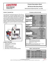
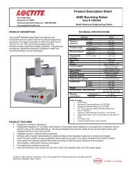
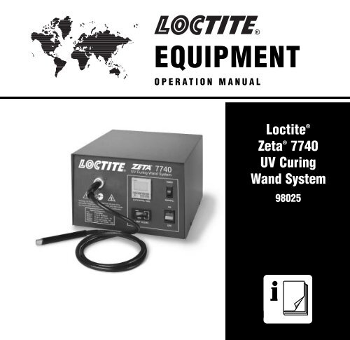
2 Description (continued)The exposure time can be controlled in either the manual mode or the timed mode. Depressingthe foot switch operates the manual mode. The shutter will remain open as long as the footswitch is engaged. In the timed mode, setting the countdown timer from zero to 99.9 secondscontrols the exposure. The timed exposure starts by momentarily engaging the foot switch. Thisaction begins the timer and the shutter will remain open until the countdown timer reaches zero.The ZETA ® 7740 can also be actuated by external devices using the foot switch 9 pin Dconnector and making a dry-contact relay closure across pins 1 and 9.2.2 Operating Elements and Connections, refers to figure 1.☞1 Power Switch2 Mode Selector SwitchWhen set to “manual” the UV light passes through the light guide for as long as thefoot switch is depressed. In the “timed” mode the timer’s LCD indicates the exposure timeand the cycle is initiated when the foot switch is momentarily depressed.3 Lamp Hour MeterThe hour meter indicates the cumulative time that the lamp has been ON.4 Timer – Expose TimeControls the period of time the shutter is opened. The UV time is set by pressing thebuttons located directly under the LCD, which indicates seconds. The manual/timedselector switch must be set to “timed.” When the foot switch is depressed the shuttermechanism will open for the indicated time and the timer will begin counting down.When the unit times out the shutter will close and the LCD will indicate the original pre-settime interval.5 Light Guide ReceptacleIs used to retain the light guide.6 Foot Switch ConnectionStandard 9 pin “D” connector for foot switch or other external switch.7 Power Inlet Module8 Power FuseIs located in the power module.9 Hour Meter Reset ButtonResets the hour meter to “0” when the button is depressed.Notice:This should only be done when a new lamp is installed.3
OMRON2 Description (continued)7740UV Curing Wand System5Light GuideReceptacleTIMER43S2.22.2 S21TIMED2Mode SelectorSwitchUVRESETH5CRMODEDISPLAYEXPOSURE TIMEMANUAL4Warning: UV Energy is transmitted from the end of thelight guide. Protective eyewear equipped with side shieldsare required that meet ANSI Z80.3 & Z87.1 Certification.Spare ComponentsP/N Description984818 Lamp & Reflector983677 Single Light Guide, 1M983684 Dual Light Guide, 1M983800 Single Light Guide, 1.5MHOURSCURTIS110LAMP HOURSONOFF1PowerSwitch3Rocky Hill, Connecticut 06067, U.S.A.Model No.: 98025 U.V. Curing Wand SystemInput: 90-132 VAC, 50/60 Hz, 1.4 A @ 120 VACLamp: 100 WattFuse: 4 Amp, 250 VMade in U.S.A., Technical Assistance: 1-800-Loctite6Foot SwitchConnectionAIR INTAKEAIR EXHAUSTWarningDisconnect and Refer toManual Before Servicing Unit.RESETPower Inlet Module& Fuse Holder78Lamp Hour Meter Reset Switch9Figure 14
3 Technical Data3.1 Energy RequirementsPower Supply: Auto RangingInput VoltagePower Protection:Auxiliary Control Voltage:90-132 VAC or 180-265VAC, 50/60Hz4A/250V fuse, 5 mm x 20 mm24 volts DCMain fuse located in power module: 5A, 250V, 5 mm x 20 mm3.2 DimensionsWidthDepthHeightWeight:11.0 inches12.5 inches7.6 inches19.5 poundsLight Guides ( supplied separately)Single end light guide, part 983677 – 1000 mm long x 5 mm diameterSingle end light guide, part 983800 – 1500 mm long x 5 mm diameterDual end light guide, part 983684 – 1000 mm long x 3 mm diameter3.3 UV Output CharacteristicsInitial output:UV Spectral Range:Primary Peak:Secondary Peaks:9 to 12 W/sq.cm250 – 400 nM365 nM315, 335 nM4 Installation4.1 Space RequirementsA space of 12" wide x 16" deep x 8" height is required. It is important to have at least 8 inchesof space behind the unit to insure proper airflow. The Loctite ® ZETA ® 7740 UV Curing Systemonly needs to be connected to a 120V/60Hz outlet to operate.Caution!Do not block the intake and exhaust fans located on the back of the housing.Caution!The unit should always be operated with the rubber support feet resting on a flat surface.5
4 Installation (continued)Caution!Do not operate with the unit resting on its side or at an angle greater than 15 degrees, frontto back.4.1.1 Lamp Installation – New UnitCaution!Do not touch the lamp module reflector or the lamp. Contaminants from hands will create “hotspots” and cause the module to fail prematurely. If either the lamp or reflector is accidentallytouched, carefully wipe them with a clean, soft cloth and isopropyl alcohol.1. Switch power off and unplugthe unit.Large Diameter Pin2. Remove four screws fromsides of housing and lift offthe cover.3. Pull back on the spring-loadedplunger and insert lampmodule into lamp mount plateand release plunger (seefigure 2).4. Remove the two power leadsfrom the foam block.5. Connect small diameter lead tofront of lamp and largediameter lead to back of lamp(see figure 2).6. Replace the cover andinstall screws.Spring Loaded PlungerLamp ModuleSmall Diameter PinOn Far Side Of LampLamp Mount PlateFigure 26
5 Operating the Unit5.1 Inserting and Removing the Light Guides☞Caution!Be sure to remove the plastic end caps before attempting to use the light guide.Caution!If the free end of the light guide is secured at a fixed location, sharp bends should be avoided asit will cause a decrease in UV power.Caution!Never pull on the jacketing portion of the light guide. During installation or removal, grasp thelight guide on the strain relief nearest the input end of the light guide.• Installing single light guide - Insert the large end of single light guide into the light guidereceptacle located on the left side of the front panel. Push light guide firmly until it isfully engaged.• Installing dual light guide – Insert the dual wand light guide into the light receptacle androtate the collar assembly so that the scribed line on the collar is in the 12 o’clock position.See section 5.4 “Adjusting Wand for Maximum Output.”Notice:It is important that the rotational position of a dual light guide be set to maximize the UV outputfor each wand. This setting is specific to each curing unit and light guide (See section 5.4 -Adjusting Dual Wand).5.2 Powering Up☞1. Plug the power cord into the receptacle located at the bottom left of the rear panel.2. Plug the cord into the 120V/60Hz outlet.3. Ensure that the lamp and light guide have been installed and the cover securely fastened.4. Install foot switch.5. Turn on the main power switch, the red switch will light up.6. Check the fans for airflow.7. Allow approximately five minutes for the lamp to reach full power.Notice:Avoid shutting the main power off for brief periods of time. Frequent start-ups will cause thelamp to decay at an accelerated rate. If the system is shut down, wait a minimum of ten minutesbefore restarting. Once the lamp is ignited, allow it to operate for a minimum of fifteen minutesbefore turning it off.7
5 Operating the Unit (continued)5.3 Setting Exposure Time5.3.1 Timed Mode1. Set the selector switch to “timed.”2. Set the timer to the desired UV exposure time. Depressing the buttons located under thedisplay on the countdown timer sets exposure time.3. Momentarily engage the foot switch to initiate a timed cycle. The UV exposure will end oncethe cycle is timed out.Notice:Timed exposure cycles may be initiated by using an externally operated device, such as a PLCcontrolled relay in place of the foot switch.5.3.2 Setting Exposure Time / Manual Mode1. Set the selector switch to “manual.”2. Press the foot switch for as long as UV exposure is needed.3. Releasing the foot switch will immediately end the exposure.5.3.3 Lamp Hour MeterThe lamp hour meter records the accumulated time the lamp has been operating. This metershould be reset only when a new lamp module is installed. A reset button is located on the rearof the unit. See figure 1.☞8
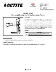
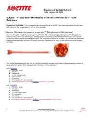
OMRON4 3RESET2 15 Operating the Unit (continued)5.4 Adjusting Dual Wand for Maximum OutputScribe LineThis Set Screw LocksThe Balancing AdapterTo The Unit BaseThis Set Screw LocksThe Light Guide InPosition After BalancingOutput Power2.27740UV Curing Wand SystemTIMERS2.2 STIMEDUVWarning: UV Energy is transmitted from the end of thelight guide. Protective eyewear equipped with side shieldsare required that meet ANSI Z80.3 & Z87.1 Certification.Spare ComponentsP/N Description984818 Lamp & Reflector983677 Single Light Guide, 1M983684 Dual Light Guide, 1M983800 Single Light Guide, 1.5MH5CREXPOSURE TIMEHOURSMODECURTISDISPLAY110LAMP HOURSMANUALONOFFFigure 3ObjectiveBalance the UV output from the two light guides of Loctite ® P/N 984589.Tools Needed3/32 inch hex keyUV radiometer –Loctite ® ZETA ® Meter 7020; P/N 98002Setup1. Install the collar assembly over the part of the light guide receptacle that protrudes from thefront of the unit. Rotate the collar assembly until the scribed line is in the 12 o’clock position.Use the set screw to secure the collar in that position.2. Insert the input end of the light guide into the light guide receptacle/collar assembly pushingit as far forward as it will go. Tighten the set screw on to the light guide.3. Turn on electric power to unit.4. Set shutter timer to 2 seconds.9
5 Operating the Unit (continued)☞5. Insert one of the light guide ends into a Loctite ® ZETA ® 7020 radiometer.6. Press the radiometer start switch.7. Actuate foot switch to open shutter.8. Release the radiometer start switch while the shutter is still opened.9. Read and record the radiometer reading.10. Position the second light guide in the radiometer.11. Press the radiometer start switch.12. Actuate foot switch to open shutter.13. Release the radiometer start switch while the shutter is still opened.14. Read and record the radiometer reading.15. Compare the two radiometer readings.16. If the lower reading is equal to or greater than 90% of the higher reading, the dual wand isbalanced.17. If the lower reading is less than 90% of the higher reading, loosen the set screw and rotatethe collar a small increment around the light guide receptacle. Use the set screw to securethe collar in that position.18. Take and compare another set of radiometer readings.19. Continue until the lower reading is equal to or greater than 90% of the higher reading.20. Tighten setscrews to lock the input end of the dual wand in position.Notice:If a radiometer is not available, it is recommended that Loctite Service be contacted at1-800-LOCTITE (1-800-562-8483) to insure optimum performance when installing a new dualended light guide.5.5 Using Foot switch / Remote DeviceThe ZETA ® 7740 can also be actuated using a foot switch or by external devices. The footswitch connection is made up of a 9 pin D connector. Making a dry-contact relay closure acrosspins 1 and 9 can actuate the unit.10
6 Care and Maintenance☞☞☞Notice:It is recommended that the UV output from the lamp be monitored regularly using a Loctite ®Zeta ® 7020 radiometer. If a radiometer is not used to monitor the lamp, it is recommended thatthe lamp be replaced when the hour meter, located on the front panel, indicates that 1,000hours of operating time has elapsed. It is normal for the lamp output to slowly decline overoperating time, however, the effective life of the lamp will decrease significantly if it is turned onand off frequently.Caution!It is recommended that the end of the light guide be positioned no closer than 1/2 inch from theLoctite ® product being cured. The heat transmitted by the lamp can adversely affect theproperties of the cured product or possibly cause damage to the part surface.Notice:Vapors from some products may gradually accumulate on the end of the light guide, reducingthe UV output. It should be inspected regularly and cleaned as necessary using isopropylalcohol and a soft, clean cloth.Caution!Avoid placing sharp bends in the light guide. This reduces the UV output and may permanentlydamage the light guide. If the light guide is mounted on a fixture, secure it by the metal exitfitting and not the flexible plastic section.Notice:The intake and exhaust fan filter elements should be replaced as needed to insure propercooling of the power supply and UV lamp assembly. They should be inspected routinely.6.1 Replacing the Lamp Module – See figure 3.Caution!Do not touch the lamp module reflector or the lamp. Contaminants from hands will create “hotspots” and cause the module to fail prematurely. If either the lamp or reflector is accidentallytouched, carefully wipe them with a clean, soft cloth and isopropyl alcohol.1. Switch power off and unplug the unit.2. Allow several minutes for the lamp to cool.3. Remove the four screws from the sides of housing and lift off the cover.4. Remove the two power leads from the old lamp.5. Pull back on the spring-loaded plunger and lift the old lamp out.6. Install the new lamp module and re-connect the power leads.7. Replace the cover.WARNING!The UV lamp used in this unit contains a very small amount of mercury. Disposal oflamps should be done in accordance with state and local regulations.11
7 TroubleshootingType of Malfunction Possible Causes CorrectionsPower does not come on – No voltage present. • Check wall circuit.(On/off switch does not light – Defective Fuse. • Replace fuse.and fans do not operate). – Defective Power Supply. • Call 800-562-8483.– Defective Switch. • Call 800-562-8483.The shutter mechanism can be – Lamp failure. • Replace lamp module.heard opening and closing, but no – Defective power supply. • Call 800-562-8483.light is emitted from the light guidePower comes on but light is not – Foot switch is not plugged in properly. • Check foot switch connection.emitted from the light guide. The – Defective foot switch. • Call 800-562-8483.shutter mechanism makes no – Defective shutter mechanism. • Call 800-562-8483.noise when foot switch is engaged.All system functions appear to be – UV output has declined due to normal • Replace lamp module.operating, but the product does lamp aging.not cure completely, or if a – End of light guide has an accumulation • Clean light guide with softradiometer is used to monitor the of product or other contaminants. cloth and isopropyl alcohol.UV output, the power is low. – Light guide is not fully inserted • Check light guide connection.in receptacle.– Light guide has exceeded its useful life • Replace light guide.12
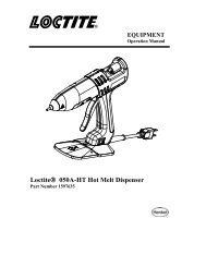
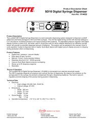
8 Documentation8.1 Wiring DiagramSHUTTER SOLENOIDTIMEDFOOT SWITCHJUMPERMODE SELECTORSWITCHMANUAL67 8910SIGTIMERPWR IN- +1 2N-0RELAY3 45-RST+ SIGHOUR METER24 VDC OUTPUT-+LAMP-POWER SUPPLY/BALLASTREF:BUSSMAN FUSEGDB-4A FAST ACTINGMOMENTARYRESET SWITCH+ON/OFF SWITCHLIGHTED-REDGROUND TO CHASISGROUND TOCHASISN-OSNAP SWITCHMOUNTED ONPARTITIONINPUT POWER MODULEREF: BUSSMAN FUSE GDA-6.3FAST ACTINGFigure 413
8 Documentation (continued)8.2 Pin Connections9 PIN D CONNECTOR & SHELLWIRE1FOOTSWITCH132345678WIRE9Figure 514
8 Documentation (continued)8.3 Replacement Parts and AccessoriesLoctite Part Number Description984818 Replacement Lamp Module983677 Single End Light Guide (5 mm x 1M)983684 Dual Ended Light Guide (3 mm x 1M)983800 Single Light Guide (5 mm x 1.5M)984770 Fan Filter Element, Quantity 597210 UV Safety Glasses97201 Foot Switch Assembly98002 Loctite ® ZETA ® 7020 UV Spot Cure Radiometer985045 Dual Wand Adapter Kit15
9 WarrantyLoctite expressly warrants that all products referred to in this Instruction Manual for model98025 UV Curing Wand System, (hereafter called "Products"), shall be free from defects inmaterials and workmanship. Liability for Loctite shall be limited, as its option, to replacing thoseProducts which are shown to be defective in either materials or workmanship or to credit thepurchaser the amount of the purchase price thereof (plus freight and insurance charges paidtherefor by the user). The purchaser’s sole and exclusive remedy for breach of warranty shall besuch replacement or credit.A claim of defect in materials or workmanship in any Products shall be allowed only when it issubmitted in writing within one month after discovery of the defect or after the time the defectshould reasonably have been discovered and in any event, within 2 years after the delivery ofthe Products to the purchaser. This warranty does not apply to perishable items, such as fusesand fan filters. The lamp is fully warranted for 500 hours of operation for failure to ignite. Thelamp is also warranted to produce 60% of the rated intial output at 500 hours of operating time.No such claim shall be allowed in respect of products which have been neglected or improperlystored, transported, handled, installed, connected, operated, used or maintained. In the event ofunauthorized modification of the Products including, where products, parts or attachments foruse in connection with the Products are available from Loctite, the use of products, parts orattachments which are not manufactured by Loctite, no claim shall be allowed.No Products shall be returned to Loctite for any reason without prior written approval fromLoctite. Products shall be returned freight prepaid, in accordance with instructions from Loctite.NO WARRANTY IS EXTENDED TO ANY <strong>EQUIPMENT</strong> WHICH HAS BEEN ALTERED,MISUSED, NEGLECTED, OR DAMAGED BY ACCIDENT, OR IF THE SYSTEM USED TODISPENSE ANY LIQUID MATERIAL OTHER THAN LOCTITE PRODUCTS.EXCEPT FOR THE EXPRESS WARRANTY CONTAINED IN THIS SECTION, LOCTITEMAKES NO WARRANTY OF ANY KIND WHATSOEVER, EXPRESS OR IMPLIED, WITHRESPECT TO THE PRODUCTS.ALL WARRANTIES OF MERCHANTABILITY, FITNESS FOR A PARTICULAR PURPOSE, ANDOTHER WARRANTIES OF WHATEVER KIND (INCLUDING AGAINST PATENT ORTRADEMARK INFRINGEMENT) ARE HEREBY DISCLAIMED BY LOCTITE AND WAIVED BYTHE PURCHASER.THIS SECTION SETS FORTH EXCLUSIVELY ALL OF LIABILITY FOR LOCTITE TOTHE PURCHASER IN CONTRACT, IN TORT OR OTHERWISE IN THE EVENT OFDEFECTIVE PRODUCTS.WITHOUT LIMITATION OF THE FOREGOING, TO THE FULLEST EXTENT POSSIBLEUNDER APPLICABLE LAWS, LOCTITE EXPRESSLY DISCLAIMS ANY LIABILITYWHATSOEVER FOR ANY DAMAGES INCURRED DIRECTLY OR INDIRECTLY INCONNECTION WITH THE SALE OR USE OF, OR OTHERWISE IN CONNECTION WITH,THE PRODUCTS, INCLUDING, WITHOUT LIMITATION, LOSS OF PROFITS AND SPECIAL,INDIRECT OR CONSEQUENTIAL DAMAGES, WHETHER CAUSED BY NEGLIGENCE FROMLOCTITE OR OTHERWISE.16
Notes17
Loctite IndustrialLoctite Corporation1001 Trout Brook CrossingRocky Hill, CT 06067-3910Loctite Automotive Technology Center2455 Featherstone RoadAuburn Hills, Michigan 48326Loctite Canada Inc.2225 Meadowpine Blvd.Mississauga, Ontario L5N 7P2Loctite Company de México, S.A. de C.V.Calzada de la Viga s/n, Fracc. Los LaurelesLoc. Tulpetlac, C.P. 55090Ecatepac de Morelos, Edo. de MéxicoMéxicoLoctite BrazilAv. Prof. Vernon Krieble, 9106690-11-ItapeviSão Paulo-Brazilwww.loctite.comLoctite and Zeta are trademarks of Loctite Corporation, U.S.A.Data in this manual is subject to change without notice.© Copyright 2001. Loctite Corporation. All rights reserved. P/N984868 Rev. B 05/05ACompany