PXH Digital Controller - Fuji Electric America
PXH Digital Controller - Fuji Electric America
PXH Digital Controller - Fuji Electric America

Create successful ePaper yourself
Turn your PDF publications into a flip-book with our unique Google optimized e-Paper software.
<strong>Fuji</strong> Instrumentation & Control<br />
High Speed control-50ms Input sampling<br />
Motorized Valve control (Position feed back/Servo control)<br />
Dual PID <strong>Controller</strong> (Heat/Cool controller)<br />
High Accurcy-0.1%<br />
Extensive number of I/O points (AI: 3 points, DI: 9 points, DO: 9 points, AO: 2 points)<br />
Enhanced Math Functions<br />
Totalize Function<br />
RS-485 Modbus Communications and Transmitter Power Supply options available<br />
ECNO:1152c
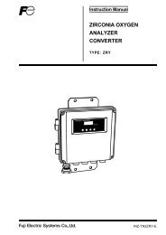
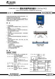
<strong>PXH</strong> <strong>Digital</strong> <strong>Controller</strong><br />
50ms sampling cycle and 0.1% accuracy offer precise control.<br />
Easy-to-view<br />
5 digit display<br />
0.01C can be indicated.<br />
Universal-input<br />
(max. 2 points)<br />
Thermocouple, RTD, voltage or<br />
current input is switchable on the<br />
front panel keys.<br />
<strong>Digital</strong>-input (Max. 9 points)<br />
Applicable to SV/PID set, AT Start/Stand-by,<br />
Remote/Auto/Manual switch, Alarm-latch clear, et. al.<br />
Auxiliary Analog input (1 point)<br />
Applicable to flow compensation and remote SV<br />
setting.<br />
Math functions<br />
Flow compensation, High/Low selector control, ratio,<br />
calorie calculation, et. al.<br />
PC loader interface and software<br />
through RS-232C Communication<br />
The loader software enables easy parameter setup.<br />
2<br />
Totalize Function<br />
Recipe Function<br />
Input Linearize Function<br />
Control-output<br />
(3 types)<br />
Selectable as relay, SSR/SSC<br />
drive and current.<br />
<strong>Digital</strong>-output<br />
(Max. 9 points)<br />
Various event data as alarm<br />
and timer output are available.<br />
Auxiliary Analog output (Max. 2 points)<br />
Max. two points out of PV/SV/MV/DV are available as<br />
analog output.<br />
Transmitter Power Supply (Option)<br />
24V DC, 23mA max.<br />
RS485 Modbus communication<br />
function (option)<br />
PID Palette<br />
Max. 7 combinations of SV, PID are available.<br />
Quick PID<br />
ensures precise control to prevent overshoot and<br />
improve response to disturbances.<br />
Applicable to various process controls including flow<br />
control and pressure control.
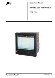
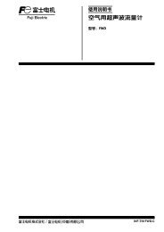
model : <strong>PXH</strong><br />
Front<br />
Panel<br />
User friendly, Easy-to-view<br />
Status indicator<br />
displays SV select No. (at operation)<br />
and parameter No. (at setting)<br />
Bargraph indicator<br />
displays MV (12 segments)<br />
Waterproof construction<br />
is equipped on front panel as<br />
standard. NEMA4x (IEC standard<br />
IP66 equivalent)<br />
User function keys<br />
offer one touch operation for Remote/<br />
Auto switch, Stand-by, Alarm-latch<br />
clear, AT, etc. is definable by user.<br />
Mode indicator<br />
displays status as stand-by, control<br />
mode, output, alarm, etc.<br />
PV indicator<br />
has 5 digit display. 0.01˚C indication<br />
is possible.(Charactor height : 20mm)<br />
SV/MV indicator<br />
displays SV and MV.<br />
(Charactor height : 13mm)<br />
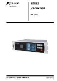
Easy<br />
configuration<br />
Application Template<br />
Pre-installed programming templates allow easy configuration for<br />
various applications.<br />
Just by selecting appropriate "Application Template", input/output setting and<br />
internal calculation blocks can be automatically configured.<br />
Template (Control Type)<br />
Position proportional control type<br />
Position feedback control type<br />
Dual control type (Heat/Cool)<br />
2 position control type<br />
2 inputs switching control type<br />
2 inputs selection control type<br />
Feed forward control type<br />
Ex-MV balance bumpless switching type<br />
.<br />
Retransm-<br />
PV<br />
Output type<br />
[Ao1T] ission<br />
output1 setting<br />
SV<br />
RET1<br />
Current<br />
MV<br />
AO 1<br />
OUT1<br />
output or<br />
Re-<br />
Re-<br />
SSR driver<br />
transm- Measure-<br />
PV<br />
transm-<br />
output<br />
PV<br />
Output Input Conditioner<br />
ment type PV1<br />
PV<br />
ission<br />
[Ao1T] ission<br />
[Ao2T]<br />
output1 value setting 1<br />
output2<br />
SV<br />
PID<br />
SV<br />
Depend on AO 2<br />
Current<br />
RET1<br />
Current<br />
RET2<br />
OUT2<br />
L<br />
operation<br />
[OTYP]<br />
output or<br />
Result of<br />
MV<br />
AO 1<br />
Local SV<br />
MV<br />
OUT1<br />
output or<br />
SV<br />
A<br />
setting<br />
Transmitter<br />
calculation<br />
Re-<br />
SSR driver<br />
supply<br />
Measure-<br />
Input<br />
PV<br />
transm-<br />
output<br />
Re-<br />
PV1<br />
[AiM]<br />
PV<br />
RUN<br />
DO 4<br />
Remote SV<br />
Relay<br />
ment<br />
ission<br />
transm-<br />
Conditioner<br />
[Ao2T]<br />
Remote<br />
PV<br />
Output type<br />
Control<br />
DO4<br />
output<br />
value 1<br />
output2<br />
SV input<br />
Ai1 Input Conditioner [RSV1]<br />
[Ao1T] ission<br />
Math<br />
PID<br />
SV<br />
Depend on AO 2<br />
Current<br />
output1<br />
RET2<br />
OUT2<br />
output1 EX-MV setting setting<br />
(Control<br />
SV<br />
Measure-<br />
Input<br />
L<br />
R<br />
MV1<br />
module<br />
operation<br />
[OTYP]<br />
output or<br />
M<br />
output)<br />
PV2<br />
RET1 [EXM1]<br />
Current<br />
Conditioner<br />
Local SV<br />
MV<br />
ment<br />
SV<br />
A<br />
Result of setting<br />
Transmitter<br />
Remote MV command<br />
AO 1<br />
Remote [REM]<br />
OUT1<br />
output or<br />
value 2<br />
supply<br />
STBY<br />
calculation<br />
command (Parameter setting or key operation)<br />
Re-<br />
SSR driver<br />
RUN<br />
DO 4<br />
Manual MV setting<br />
DO allocation<br />
Measure-<br />
Input<br />
PV<br />
transm-<br />
Aux.input<br />
Input<br />
Remote SV<br />
Relay<br />
output<br />
Ai1<br />
PV1<br />
Control [AiM]<br />
DO4<br />
PV<br />
ment<br />
ission<br />
/Remote<br />
Conditioner<br />
output<br />
Conditioner<br />
[RSV1]<br />
[Ao2T]<br />
Do1<br />
value 1<br />
output2<br />
SV input<br />
EX-MV setting<br />
output1<br />
(Control<br />
Di allocation<br />
ALM1<br />
R<br />
Math<br />
PID<br />
SV<br />
Depend on AO 2<br />
Current<br />
[EXM1]<br />
M<br />
MV1<br />
output)<br />
Measure-<br />
RET2<br />
OUT2<br />
Input<br />
L<br />
module<br />
operation<br />
Remote<br />
[OTYP]<br />
output or<br />
Remote command<br />
Do2<br />
ment PV2<br />
Conditioner<br />
Local SV<br />
MV<br />
Remote<br />
Remote<br />
SV<br />
A<br />
acknowledge<br />
setting<br />
Transmitter<br />
ALM2<br />
[REM]<br />
value 2<br />
STBY<br />
command (Parameter setting or key operation)<br />
R-ACK<br />
acknowledge<br />
Di1<br />
supply<br />
Manual MV setting<br />
DO allocation<br />
Do3<br />
RUN<br />
Manual<br />
A/M chargeover DO 4<br />
ALM3<br />
Aux.<br />
Input<br />
Relay<br />
Relay<br />
Ai1<br />
Di2<br />
SMV<br />
Control<br />
DO4<br />
input<br />
Conditioner<br />
ALM1 command<br />
output<br />
Do4 output<br />
Di allocation<br />
Do1<br />
EX-MV setting<br />
output1<br />
(Control<br />
ALM4<br />
(Do)<br />
Remote<br />
R Di3 [EXM1] No allocation<br />
Re-<br />
M<br />
MV1<br />
output)<br />
Remote<br />
acknowledge<br />
ALM2<br />
Do2<br />
transm-<br />
R-ACK<br />
EX-MV<br />
Di4 PV<br />
ission Output type<br />
EX-MV output command<br />
No allocation<br />
Do11<br />
acknowledge<br />
Di1<br />
[Ao1T] EX-MV<br />
STBY<br />
output<br />
Manual MV setting output1 setting<br />
DO allocation<br />
to<br />
Manual<br />
A/M chargeover<br />
ALM3<br />
Do3<br />
command SV<br />
* Do allocation can be<br />
Di2<br />
SMV<br />
Relay<br />
RET1<br />
Current<br />
Preset output value<br />
Do15<br />
command<br />
changed with parameters.<br />
ALM4<br />
MV<br />
AO 1<br />
OUT1<br />
output or<br />
[PMV1]<br />
Di allocation<br />
SV select<br />
Do4 output<br />
ALM1<br />
Do1<br />
* Higher priority is assigned<br />
Di3<br />
No allocation<br />
(Do)<br />
No allocation Re-<br />
SSR driver<br />
Stand-by<br />
Alarm<br />
Measure-<br />
PV<br />
Di11<br />
transm-<br />
output<br />
to designation of [OTYP]<br />
command<br />
ment<br />
PV1 Input Conditioner<br />
PV<br />
[STBY] or Do2<br />
EX-MV<br />
EX-MV output command<br />
No allocation<br />
ALM2<br />
Di4<br />
EX-MV<br />
SV select<br />
SV1<br />
ission<br />
for the output to Do4.<br />
SV select 1<br />
[Ao2T]<br />
value 1<br />
signal 1<br />
Di1<br />
Do11<br />
output<br />
output2<br />
Di allocation<br />
command<br />
PID * Do allocation can be Di15 SV to<br />
Depend on AO 2<br />
Current<br />
Do3<br />
Preset SV output select value<br />
to<br />
RET2<br />
OUT2<br />
ALM3<br />
L<br />
operation<br />
[OTYP]<br />
output or<br />
LED display allocation<br />
Di2<br />
SV select 2<br />
changed with parameters. Do15<br />
Relay<br />
signal [PMV1] 2 Local SV<br />
MV * Di allocation can be<br />
SV<br />
* Higher priority A is changed with setting<br />
Transmitter<br />
L Do1<br />
SV7<br />
assigned<br />
Do4 output<br />
ALM4<br />
No allocation<br />
SV select Stand-by<br />
parameters.<br />
supply<br />
ALM1 to 4<br />
to<br />
Di3<br />
SV select Alarm<br />
(Do)<br />
Di11<br />
3<br />
to designation of [OTYP]<br />
Indicator<br />
signal [STBY] 3 or command<br />
RUN<br />
* Since the R-ACK<br />
DO 4<br />
Relay<br />
L Do5<br />
for the output to Do4.<br />
value is Control INH at the<br />
DO4<br />
lamp<br />
Di EX-MV allocation<br />
EX-MV output command<br />
No allocation<br />
Di4<br />
EX-MV<br />
output<br />
Do11<br />
EX-MV setting<br />
time of output1 delivery, set it<br />
OR of all<br />
Di15<br />
output<br />
(Control<br />
to<br />
R<br />
LED display allocation<br />
[EXM1]<br />
M<br />
to MV1 ENA before use.<br />
* Do allocation can be<br />
the ALMs<br />
command<br />
Preset output value<br />
output)<br />
L ALM<br />
* Di allocation can be<br />
L Do1<br />
changed with parameters. Do15<br />
changed with<br />
[PMV1]<br />
parameters.<br />
ALM1 STBY to 4<br />
to<br />
Indicator<br />
* Higher priority is assigned<br />
Stand-by<br />
* Since the R-ACK<br />
No allocation Manual MV setting<br />
DO allocation<br />
Alarm<br />
Di11<br />
L Do5<br />
lamp<br />
to designation of [OTYP]<br />
[STBY] or command<br />
value is INH at the<br />
for the output to Do4.<br />
time of delivery, set it<br />
OR of all<br />
Di allocation<br />
Do1<br />
Di allocation<br />
SV select<br />
ALM1<br />
to ENA before use.<br />
Di15<br />
the ALMs<br />
L ALM<br />
LED display allocation<br />
* Di allocation can be<br />
ALM2<br />
Do2<br />
L Do1<br />
SV select<br />
SV1 changed with<br />
signal 1<br />
Di1<br />
SV select 1<br />
parameters.<br />
Do3<br />
ALM1 to 4<br />
to<br />
Indicator<br />
SV select<br />
to * Since the R-ACK<br />
ALM3<br />
Relay<br />
L Do5<br />
lamp<br />
Di2<br />
SV select 2<br />
value is INH at the<br />
signal 2<br />
Do4 output<br />
time of delivery, set it<br />
SV select<br />
SV7<br />
ALM4<br />
OR of all<br />
(Do)<br />
Di3<br />
SV select 3<br />
to ENA before use.<br />
the ALMs<br />
L ALM<br />
signal 3<br />
EX-MV<br />
EX-MV output command<br />
No allocation<br />
Di4<br />
Do11<br />
EX-MV<br />
output<br />
* Do allocation can be<br />
to<br />
command<br />
Preset output value<br />
changed with parameters.<br />
Do15<br />
[PMV1]<br />
* Higher priority is assigned<br />
Stand-by<br />
No allocation<br />
Alarm<br />
Di11<br />
[STBY] or command<br />
to designation of [OTYP]<br />
for the output to Do4.<br />
Di allocation<br />
Di15<br />
LED display allocation<br />
* Di allocation can be<br />
L Do1<br />
changed with<br />
parameters.<br />
ALM1 to 4<br />
to<br />
Indicator<br />
* Since the R-ACK<br />
L Do5<br />
lamp<br />
value is INH at the<br />
time of delivery, set it<br />
OR of all<br />
to ENA before use.<br />
the ALMs<br />
L ALM<br />
"Application Templates" are pre-installed.<br />
● PID<br />
● PID + SV select<br />
● PID + Mathematical Module<br />
● PID + SV select + Mathematical Module<br />
● PID + Input select + Mathematical Module<br />
● Heat/Cool control<br />
● Heat/Cool control with SV select<br />
● Totalization<br />
● Position feedback control<br />
● Servo control<br />
3
<strong>PXH</strong> <strong>Digital</strong> <strong>Controller</strong><br />
Easy<br />
configuration<br />
Recipe Function<br />
The value of the Parameter can be changed synchronizing with the change of<br />
the PID Palette.<br />
-10 Parameters can be registered as a Recipe Parameter for each PID Palette.<br />
PID Palette 3<br />
PID<br />
PID<br />
Palette<br />
Palette<br />
1<br />
2<br />
P7<br />
P1<br />
P7<br />
I7<br />
I7<br />
I1<br />
D7<br />
D7<br />
D1<br />
ARH7<br />
ARH7<br />
ARH1<br />
ARL7<br />
ARL7<br />
ARL1<br />
PID Palette 7<br />
P7<br />
I7<br />
D7<br />
ARH7<br />
ARL7<br />
PID Palette 1 to 7<br />
Addition of<br />
Recipe Parameter<br />
PID Palette 3<br />
PID PID Palette Palette 1 2<br />
P7<br />
P1 P7<br />
I7<br />
I1 I7<br />
D7<br />
D1 D7<br />
ARH7<br />
ARH1 ARH7<br />
ARL7 ARL7<br />
ARL1 Recipe1<br />
Recipe2<br />
Recipe1<br />
Recipe3<br />
Recipe1<br />
Recipe1 Recipe2<br />
Recipe2<br />
Recipe2 Recipe3<br />
Recipe3<br />
Recipe3<br />
Recipe10<br />
PID Palette 7<br />
P7<br />
I7<br />
D7<br />
ARH7<br />
ARL7<br />
PID<br />
Operation<br />
Recipe Parameter<br />
Recipe10<br />
Recipe10<br />
Recipe10<br />
Plastic Injection Machine.<br />
Plastic<br />
product A<br />
PID Palette + Recipe 1<br />
P =10.5 MH =90%<br />
I =67.5 ML =10%<br />
D =25 AL1 =150C<br />
Plastic<br />
product B<br />
PID Palette + Recipe 2<br />
P =75.0 MH =70%<br />
I = 2.5 ML =-3%<br />
D =59.7 AL1 =400C<br />
PV<br />
Plastic Injection Machine<br />
MV<br />
DI to chane Recipe<br />
The suitable parameter is different between<br />
Product A and Product B.<br />
The suitable parameters can be readily<br />
available by selecting Recipe number.<br />
Enhanced Functions<br />
Input Linearize Function<br />
The Linearize function can be linear converted by using the table of<br />
16 points.<br />
Linearize function has been added to all analog inputs (PV1,PV2,Ai1).<br />
output<br />
input<br />
Input block diagram<br />
User Adjustment Input Linearize Square root Inputfilter<br />
PV1,2 (TC/Pt/V/I)<br />
Ai1 (V)<br />
SPAN<br />
ZERO<br />
Math<br />
module<br />
PID<br />
module<br />
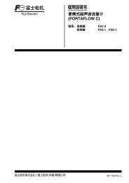
Totalize Function<br />
Totalize function can be added to all Templates.<br />
PV / Totalized value<br />
Display(7digits)<br />
Outline of specification<br />
1) Totalized value -1999999 to 9999999 (7 digits)<br />
2) Totalize source PV1, PV2, Ai1, AiM<br />
3) Totalize resolution XXX.XXXX to XXXXXXX<br />
4) Status RUN / HOLD / RESET<br />
5) Totalized value output via Re-transmission output<br />
6) Alarm output via DO1 to DO4<br />
7) Totalized data backup Backup cycle 30 seconds to EEPROM<br />
(No battery equipped)<br />
(Orifice)<br />
Totalized<br />
input<br />
Valve<br />
MV<br />
PV<br />
Boiler<br />
4
Other powerful features and functions<br />
Mathematical Module (standard feature) The number of expressions are 24 types.<br />
model : <strong>PXH</strong><br />
Useful for various applications involving process manipulation, input switching, etc. by the numeric operation<br />
between two or three inputs. User defined formulas can be applied to process and analog inputs.<br />
(Data type : Engineering unit with floating decimal point)<br />
Flow compensation, Average, High/Low selector, Input selector and etc.<br />
Constant<br />
k01-k16<br />
PV1<br />
PV2<br />
Ai1<br />
Operational expression<br />
CALC<br />
Result of operation<br />
AiM (CH7-27)<br />
●PV<br />
●Re-Transmission<br />
●Feed forward<br />
●EXMV<br />
CALC<br />
set value<br />
Name of operation<br />
0 No operation AiM= PV1<br />
*1<br />
*2<br />
1<br />
2<br />
Expression 1<br />
(Flow rate compensation calculation)<br />
Expression 2<br />
(Flow rate compensation calculation)<br />
3<br />
Expression 3<br />
AiM= k01×PV1× Ai1+k02 k04<br />
×<br />
(Flow rate compensation calculation)<br />
k03 PV2+k05<br />
PV1 : Flow rate (Differential pressure), PV2 : Temperature, Ai1 : Pressure<br />
4<br />
5<br />
Expression 4<br />
Expression 5<br />
AiM=<br />
AiM=<br />
(k01×(k02×PV1+k03×PV2+k04×Ai1)+k05)<br />
(k06×(k07×PV1+k08×PV2+k09×Ai1)+k10)<br />
(k01×((k02×PV1+k03)×(k04×PV2+k05)×(k06×Ai1+k07))+k08)<br />
(k09×((k10×PV1+k11)×(k12×PV2+k13)×(k14×Ai1+k15))+k16)<br />
6 Expression 6 AiM= k01×PV1×(k02×PV2+k03×Ai1)+k04×Ai1+k05<br />
7<br />
8<br />
9<br />
H selector, 2 points<br />
L selector, 2 points<br />
H selector, 3 points<br />
AiM= Max (PV1, PV2) Use either PV1 or PV2 input, whichever is larger, as PV.<br />
AiM= Min (PV1, PV2) Use either PV1 or PV2 input, whichever is smaller, as PV.<br />
AiM= Max (PV1, PV2, Ai1) Use one out of PV1, PV2, or Ai1 input, whichever is largest, as PV.<br />
10 L selector, 3 points<br />
AiM= Min (PV1, PV2, Ai1) Use one out of PV1, PV2, or Ai1 input, whichever is smallest, as PV.<br />
11 Input switching, 2 points<br />
AiM= PV1 when PV1k01<br />
Square root extraction cut point can be set at k06.<br />
Square root extraction cut point can be set at k07.<br />
Application example (Math Function)<br />
Flow rate compensation<br />
Math function<br />
*1 *2<br />
Ai1+k02 k04<br />
AiM= k01× PV1 × ×<br />
k03 PV2+k05<br />
PV1 : Flow rate (Differential pressure), PV2 : Temperature, Ai1 : Pressure<br />
*1<br />
Ai1+k02 k04<br />
AiM= k01×PV1× ×<br />
k03 PV2+k05<br />
PV1 : Flow rate (Differential pressure), PV2 : Temperature, Ai1 : Pressure<br />
High selection control<br />
Pressure Differential<br />
Transmitter Pressure<br />
Transmitter<br />
Thermometer<br />
Ai1 (P’)<br />
PV1 (P)<br />
PV2 (T)<br />
Math Module<br />
[Expression 2]<br />
PV<br />
AiM<br />
SV<br />
PID<br />
Operation<br />
MV<br />
Floor<br />
Temperature sensor a<br />
Temperature sensor b<br />
Temperature sensor c<br />
Signal Conditioners<br />
PV (T1)<br />
PV2 (T2)<br />
Ai1 (T3)<br />
Math Module<br />
[Expression<br />
7 or 9]<br />
PV<br />
AiM<br />
SV<br />
PID MV<br />
Operation<br />
(Orifice)<br />
: Distributor<br />
PV1 : Differential Pressure of Orifice<br />
P : Pressure of fluid<br />
T : Temperature of fluid<br />
(Control of floor temperature)<br />
The highest sensor signal is always chosen<br />
and it is used for PV<br />
Input change control<br />
BTU Calculator<br />
PV2 (T2)<br />
PV1 (T1)<br />
Math Module<br />
[Expression 11]<br />
PV<br />
AiM<br />
PID<br />
Operation<br />
MV<br />
Math<br />
Module<br />
Expression<br />
20<br />
Aim<br />
PV<br />
display<br />
Thermometer b<br />
Thermometer a<br />
Measurement temperature<br />
SV<br />
Thermocouple b<br />
IN<br />
Retransmis<br />
sion<br />
output<br />
An accurate temperature sensor is properly<br />
used at high temperature/low temperature.<br />
K01<br />
Change point (˚C)<br />
Thermocouple a<br />
Actual<br />
temperature<br />
OUT<br />
5
<strong>PXH</strong> <strong>Digital</strong> <strong>Controller</strong><br />
software<br />
Loader software enables easy parameter-settings<br />
With standard loader software, Parameters<br />
can be easily uploaded/downloaded. PID<br />
tuning status can be easily viewed on PC.<br />
Connection from standard<br />
loader port or from optional<br />
RS-485 communication.<br />
Menu<br />
Template selection<br />
Parameter settings/changes<br />
Preview for Parameter print<br />
PID tuning status<br />
Small instrumentation system is easily configurable<br />
RS-485 (MODBUS) communication allows for connecting<br />
up to 31 units using any general-purpose SCADA software.<br />
Max. 31 units can be connected by RS-485 (Modbus)<br />
Temperature Differential Pressure Pressure Flow Level Gas<br />
6
model : <strong>PXH</strong><br />
General<br />
Input<br />
Function<br />
Indication<br />
Specifications<br />
Size and Mass<br />
Power supply<br />
Power<br />
consumption<br />
External terminals<br />
Measuring value<br />
input<br />
Auxiliary analog<br />
input (option)<br />
<strong>Digital</strong> input<br />
Valve openings<br />
feed back<br />
Control method<br />
<strong>Controller</strong> type<br />
selection<br />
Control mode<br />
Alarm output<br />
Memory back-up<br />
Accuracy<br />
PV indicator<br />
SV indicator<br />
Status indicator<br />
Bargraph<br />
Mode indicator<br />
96(W)×96(H)×81.5(L)mm, 500g<br />
AC100 (-15%) - 240V (+10%), 50/60Hz<br />
15VA or less (for AC100V)<br />
20VA or less (for AC220V)<br />
Screw terminal (M3)<br />
Sampling cycle : 50ms<br />
Input type : Thermocouple, resistance bulb,<br />
DC Voltage/Current<br />
Sampling cycle : 100ms<br />
Input type DC Voltage (DC1-5V, 0-5V, 0-10V)<br />
Number of input : 4 or 9 points<br />
Specification : Contact or transistor input<br />
Contact rating : DC12V, ca.2mA per point<br />
potentiometer<br />
100-10k<br />
2-degree-of-freedom PID control with Auto<br />
tuning<br />
with application templates<br />
Auto/Manual<br />
Auto/Manual/Remote<br />
Max. 9 points as digital output<br />
by nonvolatile memory<br />
0.1%1digit of full scale<br />
LED 7 segments 5 digits (red color),<br />
charactoer height: 20mm<br />
LED 7 segments 5 digits (orange color),<br />
character height: 13mm<br />
LED 7 segments 2 digits (orange color),<br />
character height: 12mm<br />
LED 12 segments (orange color)<br />
Stand-by, Control mode, output, alarm<br />
Output<br />
RS232C<br />
communication<br />
RS485<br />
communication<br />
(Option)<br />
Applied standards<br />
Control output<br />
Analog<br />
re-transmission<br />
output<br />
<strong>Digital</strong> output<br />
Transmitter<br />
power supply<br />
Protocol<br />
Speed<br />
Protocol<br />
Speed<br />
One point to be selected from the followings<br />
1. Relay contact output<br />
Contact structure :<br />
SPDT contact (DO4 is used)<br />
Contact rating :<br />
AC220V/DC30V, 3A (Resistive load)<br />
AC220V/DC30V, 1A (Inductive load)<br />
2. SSR/SSC drive output<br />
DC12V (DC10-15V)/Max. current 20mA<br />
Load resistance : 600 or more<br />
3. DC4-20mA output<br />
Accuracy : 0.2% FS<br />
Linearity : 0.2% FS<br />
Load resistance : 600 or less<br />
Max. 2 points<br />
Current output (DC4-20mA)<br />
Output type : PV, SV, MV, DV<br />
Number of output : 2, 4, or 9 points<br />
Contact structure :<br />
SPDT contact (DO4)<br />
SPST contact (other than DO4)<br />
Contact rating :<br />
AC220V/DC30V, 1A (Resistive load)<br />
DC24V (DC17-30V)<br />
Max. current 23mA<br />
Modbus-RTU<br />
9600bps, 19200bps, 38400bps<br />
Modbus-RTU<br />
9600bps, 19200bps, 38400bps<br />
UL, CE Mark<br />
Digit<br />
4<br />
5<br />
6<br />
7<br />
8<br />
9<br />
10<br />
11<br />
12<br />
Ordering code<br />
Description<br />
<br />
96x96mm<br />
<br />
1 loop, PID controller<br />
1 loop, Heating/cooling control<br />
1 loop, Motorized valve control output with PFB<br />
1 loop, Motorized valve control output without PFB<br />
<br />
Universal input, 1 point<br />
Universal input, 2 points<br />
<br />
None<br />
DC voltage<br />
<br />
<br />
<br />
Current<br />
Current<br />
Current<br />
Current<br />
SSR/SSC drive<br />
SSR/SSC drive<br />
SSR/SSC drive<br />
<br />
100 to 240 V AC 50/60Hz<br />
<br />
None<br />
RS-485 (Modbus)<br />
T-Link<br />
<br />
4 points (DI1 to 4)<br />
4 points (DI1 to 4)<br />
9 points (DI1 to 4, 11 to 15)<br />
Note 1) The 6th digit “2” is not available with 12th digit “B”.<br />
2) 5th digit “D” is not available with 7th digit “1”.<br />
3) 6th digit “2” or 12th degit “B” is not available with 12th digit “T”.<br />
4) DO4 is used for Relay contact as control output.<br />
None<br />
Current<br />
SSR/SSC drive<br />
Transmitter power supply<br />
None<br />
Current<br />
SSR/SSC drive<br />
<br />
including control output relay output<br />
2 points (DO3, 4)<br />
4 points (DO1 to 4)<br />
9 points (DO1 to 4, 11 to 15)<br />
4<br />
<strong>PXH</strong> 1<br />
Note 1<br />
Note 2<br />
Note 3<br />
Note 4<br />
Note 1<br />
9 V 0<br />
9<br />
5<br />
A<br />
F<br />
D<br />
S<br />
6<br />
1<br />
2<br />
7<br />
0<br />
1<br />
8<br />
1<br />
9<br />
1<br />
2<br />
3<br />
5<br />
A<br />
B<br />
C<br />
10 11 12 13<br />
V<br />
0<br />
R<br />
T<br />
0<br />
A<br />
B<br />
7
<strong>PXH</strong> <strong>Digital</strong> <strong>Controller</strong><br />
model : <strong>PXH</strong><br />
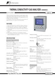
External dimensions (Unit : mm)<br />
●Front<br />
<br />
●Side<br />
10<br />
2<br />
94.5 (including<br />
terminal cover)<br />
79.5<br />
Mounting fixture<br />
●Rear<br />
6.2<br />
●Panel cut<br />
92 +0.8<br />
-0<br />
<br />
91.5<br />
93.7 (Terminal cover)<br />
107.5<br />
M3 screw<br />
92 +0.8<br />
-0<br />
116MIN.<br />
Waterproof<br />
packing<br />
t 1t 8<br />
Panel<br />
Terminal cover<br />
(option)<br />
RCJ module<br />
RCJ module<br />
100MIN.<br />
Scope of supply<br />
<strong>Controller</strong> <strong>PXH</strong>, mounting fixture, waterproof packing for front<br />
face, engineering unit sheet, instruction manual, termination<br />
resistor in case communication interface is ordered.<br />
Precautions for use<br />
To ensure temperature process safety in case of <strong>PXH</strong>'s failure, fit a separate<br />
over-temperature protection unit to isolate the heating circuit.<br />
Uncontrollability due to such failure may cause major accident.<br />
International Sales Div.<br />
Sales Group<br />
Gate City Ohsaki, East Tower, 11-2, Osaki 1-chome,<br />
Shinagawa-ku, Tokyo 141-0032, Japan<br />
http://www.fujielectric.com<br />
Phone: 81-3-5435-7280, 7281 Fax: 81-3-5435-7425<br />
http://www.fujielectric.com/products/instruments/<br />
Information in this catalog is subject to change without notice.<br />
Printed in Japan 2011-4/20FOLS