Technical Data - Douglas Lighting Control
Technical Data - Douglas Lighting Control
Technical Data - Douglas Lighting Control
- No tags were found...

You also want an ePaper? Increase the reach of your titles
YUMPU automatically turns print PDFs into web optimized ePapers that Google loves.
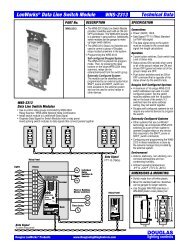
Installation<br />
Dialog Value Series<br />
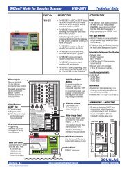
WDY-SC-CCM20 / WDY-SC-CCMBAC<br />
• WDY-SC-CCM20 & WDY-SC-CCMBAC Installation Instructions<br />
- To be installed in accordance with local and national electrical codes by a qualified electrician only.<br />
- Unit must be properly grounded.<br />
- Failure to follow these instructions could lead to serious injury or property damage.<br />
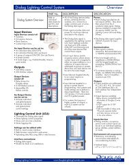
Description<br />
The WDY-SC-CCM20 & WDY-SC-CCMBAC are to be powered by a 1PH, 120-277 VAC 60Hz<br />
Class 1 circuit, which must overcurrent protected by a circuit breaker rated 20A or less. It delivers<br />
power to a lighting circuit of equal voltage rating, which may be loaded to a maximum of 15.5A.<br />
Installation Steps<br />
1. Disconnect power from the circuit to which the WDY-SC-CCM20 will be connected.<br />
2. Remove the two cover plates, one from each end. Remove and store the four 8032 Keps nuts<br />
then remove the interanla control from the housing. Put the internal control in a protected<br />
location.<br />
3. If desired, cut holes in the housing for conduit fittings; stay in region specified.<br />
4. Select a smooth surface with adequate access space for mounting the WDR-SC-CCM20. Use<br />
the four mounting holes to secure enclosure to the selected surface. Be sure to remove any<br />
debris and residue from the mounting and cutting process.<br />
5. Re-mount the internal control in the enclosure by tightening the four Keps nuts to 12-16 in-lbs.<br />
6. Route the load circuit and the power circuit (from the panel board) to the WDR-SC-CCM20<br />
and make power connections. Use 12-14AWG stranded copper conductors and torque<br />
connections to 16-18 in-lbs.<br />
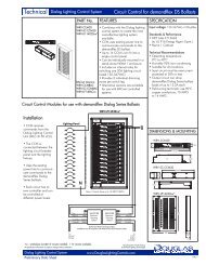
7. The connectors marked ‘Dialog BUS’ may be used for making connections to other Dialog<br />
control devices according to their specific instructions. Use CAT5e cables for this purpose.<br />
8. Replace both coverplates before reapplying power.<br />
Envelope and mounting dimensions<br />
9.695"<br />
1. Make ground connections to<br />
panelboard and branch circuit.<br />
Panelboard<br />
WDR-SC-CCM20<br />
Neutral Bus<br />
Ground Bus<br />
GROUND<br />
NEUTRAL<br />
LOAD<br />
LINE<br />
Class 1 Power Connections<br />
Ground<br />
<strong>Control</strong>led lighting<br />
circuit with demandflex<br />
Value Series ballasts<br />
2. Make neutral connections to<br />
panelboard and branch circuit.<br />
Panelboard<br />
Neutral Bus<br />
Ground Bus<br />
WDR-SC-CCM20<br />
GROUND<br />
NEUTRAL<br />
LOAD<br />
LINE<br />
Neutral<br />
Ground<br />
<strong>Control</strong>led lighting<br />
circuit with demandflex<br />
Value Series ballasts<br />
.20"<br />
CLASS 2 ACCESS<br />
1.18"<br />
.38"<br />
MOD BUS<br />
.75"<br />
.75"<br />
DANGER<br />
3.208"<br />
3. Make hot connection from LOAD<br />
to branch circuit.<br />
Neutral Bus<br />
Ground Bus<br />
GROUND<br />
NEUTRAL<br />
LOAD<br />
LINE<br />
Hot<br />
Neutral<br />
Ground<br />
4. Make hot connection from<br />
panelboard to LINE.<br />
Neutral Bus<br />
Ground Bus<br />
GROUND<br />
NEUTRAL<br />
LOAD<br />
LINE<br />
Hot<br />
Neutral<br />
Ground<br />
Dialog VS Circuit <strong>Control</strong> Module<br />
www.<strong>Douglas</strong><strong>Lighting</strong><strong>Control</strong>s.com<br />
A18.12