Technical Data - Douglas Lighting Control
Technical Data - Douglas Lighting Control
Technical Data - Douglas Lighting Control
- No tags were found...

You also want an ePaper? Increase the reach of your titles
YUMPU automatically turns print PDFs into web optimized ePapers that Google loves.
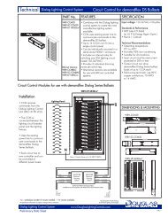
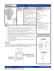
<strong>Technical</strong><br />
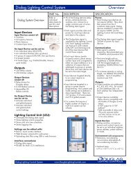
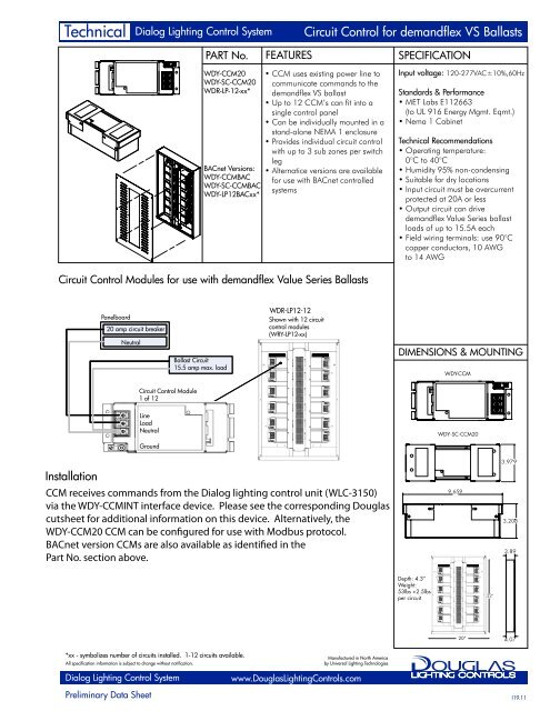
Dialog <strong>Lighting</strong> <strong>Control</strong> System<br />
Circuit <strong>Control</strong> for demandflex VS Ballasts<br />
PART No. FEATURES SPECIFICATION<br />
WDY-CCM20<br />
WDY-SC-CCM20<br />
WDR-LP-12-xx*<br />
BACnet Versions:<br />
WDY-CCMBAC<br />
WDY-SC-CCMBAC<br />
WDY-LP12BACxx*<br />
• CCM uses existing power line to<br />
communicate commands to the<br />
demandflex VS ballast<br />
• Up to 12 CCM’s can fit into a<br />
single control panel<br />
• Can be individually mounted in a<br />
stand-alone NEMA 1 enclosure<br />
• Provides individual circuit control<br />
with up to 3 sub zones per switch<br />
leg<br />
• Alternatice versions are available<br />
for use with BACnet controlled<br />
systems<br />
Input voltage: 120-277VAC±10%,60Hz<br />
Standards & Performance<br />
• MET Labs E112663<br />
(to UL 916 Energy Mgmt. Eqmt.)<br />
• Nema 1 Cabinet<br />
<strong>Technical</strong> Recommendations<br />
• Operating temperature:<br />
0°C to 40°C<br />
• Humidity 95% non-condensing<br />
• Suitable for dry locations<br />
• Input circuit must be overcurrent<br />
protected at 20A or less<br />
• Output circuit can drive<br />
demandflex Value Series ballast<br />
loads of up to 15.5A each<br />
• Field wiring terminals: use 90°C<br />
copper conductors, 10 AWG<br />
to 14 AWG<br />
Circuit <strong>Control</strong> Modules for use with demandflex Value Series Ballasts<br />
Panelboard<br />
20 amp circuit breaker<br />
Neutral<br />
Ballast Circuit<br />
15.5 amp max. load<br />
WDR-LP12-12<br />
Shown with 12 circuit<br />
control modules<br />
(WRY-LP12-xx)<br />
DIMENSIONS & MOUNTING<br />
WDY-CCM<br />
Circuit <strong>Control</strong> Module<br />
1 of 12<br />
Line<br />
Load<br />
Neutral<br />
WDY-SC-CCM20<br />
Ground<br />
Installation<br />
CCM receives commands from the Dialog lighting control unit (WLC-3150)<br />
via the WDY-CCMINT interface device. Please see the corresponding <strong>Douglas</strong><br />
cutsheet for additional information on this device. Alternatively, the<br />
WDY-CCM20 CCM can be configured for use with Modbus protocol.<br />
BACnet version CCMs are also available as identified in the<br />
Part No. section above.<br />
9.659<br />
3.979<br />
3.208<br />
3.89<br />
Depth: 4.3”<br />
Weight:<br />
53lbs +2.5lbs<br />
per circuit<br />
32"<br />
20”<br />
4.07<br />
*xx - symbolizes number of circuits installed. 1-12 circuits available.<br />
All specification information is subject to change without notification.<br />
Manufactured in North America<br />
by Universal <strong>Lighting</strong> Technologies<br />
Dialog <strong>Lighting</strong> <strong>Control</strong> System<br />
www.<strong>Douglas</strong><strong>Lighting</strong><strong>Control</strong>s.com<br />
Preliminary <strong>Data</strong> Sheet I19.11
Installation<br />
Dialog Value Series<br />
WDY-SC-CCM20 / WDY-SC-CCMBAC<br />
• WDY-SC-CCM20 & WDY-SC-CCMBAC Installation Instructions<br />
- To be installed in accordance with local and national electrical codes by a qualified electrician only.<br />
- Unit must be properly grounded.<br />
- Failure to follow these instructions could lead to serious injury or property damage.<br />
Description<br />
The WDY-SC-CCM20 & WDY-SC-CCMBAC are to be powered by a 1PH, 120-277 VAC 60Hz<br />
Class 1 circuit, which must overcurrent protected by a circuit breaker rated 20A or less. It delivers<br />
power to a lighting circuit of equal voltage rating, which may be loaded to a maximum of 15.5A.<br />
Installation Steps<br />
1. Disconnect power from the circuit to which the WDY-SC-CCM20 will be connected.<br />
2. Remove the two cover plates, one from each end. Remove and store the four 8032 Keps nuts<br />
then remove the interanla control from the housing. Put the internal control in a protected<br />
location.<br />
3. If desired, cut holes in the housing for conduit fittings; stay in region specified.<br />
4. Select a smooth surface with adequate access space for mounting the WDR-SC-CCM20. Use<br />
the four mounting holes to secure enclosure to the selected surface. Be sure to remove any<br />
debris and residue from the mounting and cutting process.<br />
5. Re-mount the internal control in the enclosure by tightening the four Keps nuts to 12-16 in-lbs.<br />
6. Route the load circuit and the power circuit (from the panel board) to the WDR-SC-CCM20<br />
and make power connections. Use 12-14AWG stranded copper conductors and torque<br />
connections to 16-18 in-lbs.<br />
7. The connectors marked ‘Dialog BUS’ may be used for making connections to other Dialog<br />
control devices according to their specific instructions. Use CAT5e cables for this purpose.<br />
8. Replace both coverplates before reapplying power.<br />
Envelope and mounting dimensions<br />
9.695"<br />
1. Make ground connections to<br />
panelboard and branch circuit.<br />
Panelboard<br />
WDR-SC-CCM20<br />
Neutral Bus<br />
Ground Bus<br />
GROUND<br />
NEUTRAL<br />
LOAD<br />
LINE<br />
Class 1 Power Connections<br />
Ground<br />
<strong>Control</strong>led lighting<br />
circuit with demandflex<br />
Value Series ballasts<br />
2. Make neutral connections to<br />
panelboard and branch circuit.<br />
Panelboard<br />
Neutral Bus<br />
Ground Bus<br />
WDR-SC-CCM20<br />
GROUND<br />
NEUTRAL<br />
LOAD<br />
LINE<br />
Neutral<br />
Ground<br />
<strong>Control</strong>led lighting<br />
circuit with demandflex<br />
Value Series ballasts<br />
.20"<br />
CLASS 2 ACCESS<br />
1.18"<br />
.38"<br />
MOD BUS<br />
.75"<br />
.75"<br />
DANGER<br />
3.208"<br />
3. Make hot connection from LOAD<br />
to branch circuit.<br />
Neutral Bus<br />
Ground Bus<br />
GROUND<br />
NEUTRAL<br />
LOAD<br />
LINE<br />
Hot<br />
Neutral<br />
Ground<br />
4. Make hot connection from<br />
panelboard to LINE.<br />
Neutral Bus<br />
Ground Bus<br />
GROUND<br />
NEUTRAL<br />
LOAD<br />
LINE<br />
Hot<br />
Neutral<br />
Ground<br />
Dialog VS Circuit <strong>Control</strong> Module<br />
www.<strong>Douglas</strong><strong>Lighting</strong><strong>Control</strong>s.com<br />
A18.12
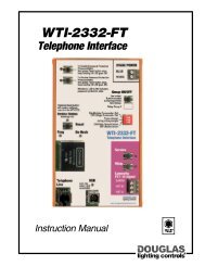
Installation<br />
Dialog Value Series<br />
WDY-SC-CCM20 / WDY-SC-CCMBAC<br />
• WDY-SC-CCM20 & WDY-SC-CCMBAC Circuit <strong>Control</strong> Module<br />
DCL ballast circuit<br />
16 amp max. load<br />
Neutral<br />
20 amp circuit breaker<br />
GND<br />
Neutral<br />
Load<br />
Circuit <strong>Control</strong> Module<br />
Line<br />
AFTER WIRING, REASSEMBLE BOTH COVERS,<br />
TIGHTEN SCREWS TO 12-15 IN. LBS.<br />
CLASS 2<br />
(CONTROL SIDE)<br />
GROUND LUG<br />
(TIGHTEN GROUND<br />
LUG SCREW TO<br />
32-36 IN. LBS.)<br />
CLASS 1<br />
(POWER SIDE)<br />
KNOCKOUT<br />
AREA<br />
Dialog VS Circuit <strong>Control</strong> Module<br />
www.<strong>Douglas</strong><strong>Lighting</strong><strong>Control</strong>s.com<br />
A18.12