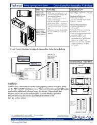
nonelectrical
Relays + PWEx Panels + Transformers.pdf - Douglas Lighting Control
Relays + PWEx Panels + Transformers.pdf - Douglas Lighting Control
- No tags were found...

Create successful ePaper yourself
Turn your PDF publications into a flip-book with our unique Google optimized e-Paper software.
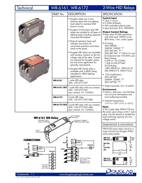
Technical<br />
WR-6161, WR-6172<br />
2-Wire HID Relays<br />
2-WIRE RELAY TECHNOLOGY<br />
• Douglas 2-wire relays utilize an ingenious control method that<br />
permits simple and minimal wiring. All functions for low voltage<br />
control: on, off, indication and location are provided with<br />
only a 2-wire connection of which one is often a common. All<br />
Douglas relays manufactured over the past 30 years utilize the<br />
same principle. Thus, any Douglas switching device is<br />
compatible with any model of Douglas relay.<br />
Manual<br />
Lever<br />
Detailed 2-wire Relay / Switch Circuit<br />
Transformer<br />
24VAC<br />
W<br />
B<br />
Blue<br />
White<br />
2-wire Switch<br />
Switch<br />
Operational Principle<br />
• A negative pulse turns the relay ON and a positive pulse turns it<br />
OFF. Using a diode, an AC signal can be rectified to turn the relay<br />
either ON or OFF. Douglas switches have 2 diodes built into the<br />
switch to provide the ON and OFF signals.<br />
• The relay has 2 similar diodes built inside that are in series with the<br />
relay coil. The diodes in the relay act as gates for the switch signal.<br />
• To turn the relay ON or OFF, the rocker switch completes the circuit<br />
by selecting the ON or OFF diode. If the diode selected is in the<br />
same direction as the gate diode in the relay, the relay will switch. If<br />
the gate diode is not in the correct direction, then nothing will<br />
happen since the relay is already in the correct state for the action<br />
selected by the switch. When the switch is released, a spring returns<br />
it to the central neutral position .<br />
• Indication (ON state) and location (OFF state) are obtained by<br />
utilizing LED diodes built into the switch. Only the LED which is<br />
connected in the same direction as the gate diode in the relay will<br />
light. Although the LED current passes through the relay coil, it is<br />
not large enough to cause the relay to trip. However, there is a limit:<br />
the maximum number of LED switches that can be connected to the<br />
same relay is . 6<br />
• For additional convenience (especially during installation) all standard<br />
models have a manual control lever and indicator permitting a <strong>nonelectrical</strong><br />
method of switching and status check at the panel.<br />
Latch to lock relay ON<br />
or OFF (actually done<br />
with magnetics)<br />
Tr<br />
Tr<br />
W<br />
B<br />
Relay<br />
W<br />
B<br />
2-wire<br />
Relay<br />
Gate Diodes<br />
Relay Coil<br />
Red<br />
Control Diodes<br />
Switch<br />
Switching ON<br />
Switch pressed to ON position.<br />
ON pulse ( ) sent to relay and<br />
relay begins to switch over to ON .<br />
Switch<br />
Detailed LED Switch Circuit *<br />
Transformer<br />
24VAC<br />
W<br />
B<br />
Blue<br />
White<br />
LED 2-wire Switch<br />
ON<br />
ON<br />
Relay<br />
Switched ON<br />
Relay completed switching to ON position.<br />
OFF gate diode engaged and ON pulse<br />
from switch is stopped by OFF gate diode.<br />
Relay ready for OFF pulse.<br />
2-wire Relay<br />
Red<br />
Gate Diodes<br />
Relay Coil<br />
OFF<br />
OFF<br />
Control<br />
Diodes<br />
LED<br />
Indicator Diodes<br />
Current limiting<br />
Resistor<br />
Tr<br />
W<br />
B<br />
Switch<br />
*<br />
LED Switch circuit actually not<br />
as shown. Switch is functionally<br />
similar except rocker switch is<br />
replaced with single push button.<br />
Relay<br />
Switching OFF<br />
Switch pressed to OFF position.<br />
OFF pulse ( ) sent to relay and<br />
relay begins to switch over to OFF.<br />
Components 1.2<br />
A-1.1,2,3,4 -Relays & Panels, HID<br />
www.DouglasLightingControls.com
Technical<br />
Relay Panels for HID Relays<br />
PWEx Panels<br />
PART No.<br />
PWEx Panels<br />
DESCRIPTION<br />
• Douglas PWEx series relay<br />
panels are a versatile line of<br />
panels used for WR-6161 &<br />
WR-6172 relays.<br />
• Standard sizes range from 6 - 72<br />
relays. (Note:WR-6172= 2 relays).<br />
• A panel consists of the enclosure<br />
(tub), the interior and the cover.<br />
Enclosures are installed in the<br />
rough-in stage and interiors are<br />
installed and connected after<br />
wires are pulled.<br />
• Interior has snap brackets for<br />
mounting relays and DIN rail in<br />
the centre for mounting control<br />
components.<br />
• Box knockouts are located so that<br />
panels of the same horizontal or<br />
vertical dimension can be joined<br />
with conduit nipples.<br />
SPECIFICATION<br />
• Enclosures and covers are made<br />
of steel coated with ANSI/ASA<br />
61 Grey. Coating is heat fused<br />
polyesther epoxy finish applied<br />
on all surfaces.<br />
• Interior insert is made from<br />
aluminum, stell and plastic parts.<br />
Certifications<br />
• UL listed, CSA approved.<br />
EEMAC/NEMA 1 Standard.<br />
Options<br />
• Hinged, surface or flush covers.<br />
Covers are reversable for either<br />
left-to-right or right-to-left door<br />
opening. Driphoods (surface<br />
mount only). NEMA 3 standards.<br />
Special paint colors. Voltage<br />
dividers to divide line voltage<br />
compartment for different line<br />
voltages.<br />
4"<br />
4"<br />
Compartment Style<br />
Barrier Layout<br />
4"<br />
CAPACITY<br />
6 12 24<br />
PART No.<br />
PWE0 - C06M - ** PWE1 - C12M - ** PWE2 - C24M - **<br />
SIZE (H x W x D)<br />
12 x 12 x 4.25 20 x 14 x 4.25 33 x 14 x 4.25<br />
PWEx Panel Numbering System<br />
** Add cover style number at end of P/N<br />
Enclosure<br />
PWEx<br />
C<br />
W<br />
Interior<br />
xx<br />
M<br />
S1<br />
F2<br />
Cover<br />
or<br />
S3<br />
F4<br />
4½"<br />
3"<br />
Box Code<br />
Barrier Layout<br />
Compartment: C<br />
Wireway: W<br />
Capacity<br />
Relay Code<br />
HID relays: M<br />
Screw-on<br />
Surface: S1<br />
Flush: F2<br />
Hinged<br />
Surface: S3<br />
Flush: F4<br />
4½"<br />
3"<br />
4½"<br />
3"<br />
4½"<br />
3"<br />
Symbols<br />
Low voltage area<br />
Line voltage area<br />
HID relay<br />
Transformer<br />
Wireway Style<br />
Barrier Layout<br />
CAPACITY<br />
PART No.<br />
SIZE (H x W x D)<br />
6"<br />
24<br />
PWE3 - W24M - **<br />
27 x 20 x 4.25<br />
6" 6"<br />
36 48 72<br />
PWE4 - W36M - ** PWE6 - W48M - ** PWE8 - W72M - **<br />
33 x 20 x 4.25<br />
** Add cover style number at end of P/N<br />
39 x 20 x 4.25<br />
7"<br />
54 x 20 x 4.25<br />
Components 1.3<br />
A-1.1,2,3,4 -Relays & Panels, HID<br />
www.DouglasLightingControls.com
Technical<br />
Relay Panels for HID Relays<br />
PWEx Panels<br />
PWEx Panels: Exploded View<br />
Drip Shields<br />
Optional, surface cover<br />
panels only.<br />
Screw-on<br />
Covers<br />
Hinged Covers<br />
Surface (S1) or<br />
Surface (S3) or Flush (F4). Flush (F2)<br />
Install right side up or upside down<br />
for right-to-left or left-to-right door.<br />
The inner trim of the hinged cover<br />
covers over all of the line voltage wiring.<br />
Access to the relay's manual control<br />
levers is in the low voltage compartment.<br />
Relay Interior<br />
Relays mount to HID snap rails.<br />
Barriers are located to provide the<br />
line / low voltage division.<br />
Transformers mount to 1/2" knock<br />
outs located in the barrier.<br />
Control components are mounted<br />
to DIN rail in center of interior.<br />
Pre-assembled PWEx panels will<br />
have panel schedules completed<br />
according to information provided<br />
and all low voltage control<br />
connections pre-wired.<br />
INSTALLATION & ASSEMBLY<br />
PWEx series relay panels for Douglas HID relays are supplied<br />
with a separate interior. All of the components and barriers are<br />
mounted to the interior.<br />
Stacking Panels<br />
Panels of equal dimension on a<br />
side have matching KO pattern<br />
to provide easy stacking.<br />
PWEx panels are primarily intended for projects where the interior<br />
is factory pre-assembled. To install the relay panel the following<br />
sequence is recommended:<br />
1) Mount the empty enclosure onto the wall and pull wires. It is<br />
recommended that all (or most) of the wires be pulled prior to<br />
installing the interior. This will prevent component damage<br />
from the wire pulling operation.<br />
2) Relay line voltage terminals are sized for a maximum of<br />
12AWG wire.<br />
For low voltage wiring 18AWG solid is recommended.<br />
3) Once the wires have been pulled, install the interior and bolt it<br />
into place. Make line connections to relays according to the<br />
panel schedule provided. If there is no schedule, identify<br />
circuits on a blank schedule.<br />
4) To test circuit, turn circuit breaker off, use manual lever to turn<br />
relay on and then turn on the circuit breaker. This will help<br />
prevent relay contact welding due to dead shorts.<br />
5) Verify that the schedule matches the lights operated by the<br />
relay.<br />
6) Once the line circuits are connected and verified, connect low<br />
voltage switch wiring to relays or devices.<br />
Components 1.4<br />
A-1.1,2,3,4 -Relays & Panels, HID<br />
www.DouglasLightingControls.com
Technical<br />
WR-4075, WR-4040<br />
Transformers<br />
CONNECTIONS<br />
Lights<br />
H<br />
Breaker<br />
Transformer<br />
24VAC<br />
W<br />
B<br />
Relays<br />
Number of Relays<br />
per Switch<br />
White<br />
Blue<br />
Red<br />
PART No.<br />
WR-4075-<br />
120/277<br />
WR-4075-<br />
120/347<br />
WR-4075-240<br />
Wire Length<br />
One way measure<br />
in feet (meters)<br />
WR-4040-120<br />
WIRE DISTANCE CHART - 18Ga Wire<br />
120/277V Primary<br />
: 24VAC* Secondary<br />
120/347V Primary<br />
: 24VAC* Secondary<br />
240V Primary<br />
: 24VAC* Secondary<br />
One-way Measurement - feet (meters)<br />
Wire Gauge<br />
American<br />
Wire Gauge<br />
DESCRIPTION<br />
The transformer supplies the<br />
switching for Douglas 2-wire relay<br />
control. 2-wire relays are latching<br />
type and only require power to<br />
switch on or off. One transformer is<br />
sufficient to service many relays<br />
and devices.<br />
WR-4075 Series: Standard Duty<br />
• 40VA steady draw, 75VA pulsed draw.<br />
• Current limiting and internally fused with an<br />
automatically resetting thermal fuse.<br />
* Secondary voltage varies from<br />
24V to 29V depending upon load.<br />
WR-4040 Series: Light Duty<br />
• 40VA steady draw, 40VA pulsed draw.<br />
• Current limiting and internally fused with a one<br />
time event fuse.<br />
120V Primary : 24VAC Secondary<br />
Sw<br />
SPECIFICATION<br />
Input<br />
• Line voltage 120,240,277 or<br />
347V. Select correct model fo<br />
line voltage.<br />
Output<br />
• 24VAC at full load. At no or low<br />
loads, the voltage is 29V. As the<br />
current draw increases, the<br />
transformer voltage decreases. A<br />
fully loaded class 2 transformer<br />
will output 24V.<br />
• Douglas products are designed to<br />
operate correctly over the entire<br />
range of voltages provided by th<br />
transformer.<br />
Class 2 - Current Limiting<br />
• Transformers that are approved<br />
for powering Class 2 circuits are<br />
current limited to prevent<br />
excessive currents caused by<br />
shorts. This is a key safety feature<br />
to help prevent fires from shorts.<br />
• The Class 2 current limiting<br />
feature permits the use of wire<br />
that is of a light gauge and has<br />
less stringent insulation<br />
requirements.<br />
Environment<br />
• Indoors, stationary, non-vibrating,<br />
non-corrosive atmosphere and<br />
non-condensing humidity.<br />
• Ambient temperature:<br />
-20°F to +120°F (-28°C to +50°C)<br />
Approvals & Certifications<br />
• UL Approved<br />
• CSA Certified<br />
DIMENSIONS & MOUNTING<br />
Douglas transformers have a<br />
nipple & mounting nut suited for a<br />
7/8" hole (1/2" pipe hole & tread size)<br />
3.15<br />
WR-4075<br />
Series<br />
Transformers<br />
1.5A & 3.0A rated switches<br />
(WR-8001, WR-8501, WR-8503)<br />
1<br />
2<br />
3<br />
4<br />
2000 (600)<br />
1500 (450)<br />
1000 (300)<br />
500 (150)<br />
18 AWG<br />
18 AWG<br />
18 AWG<br />
18 AWG<br />
2.56<br />
2.38<br />
6"wire<br />
3.15<br />
WR-4040<br />
Series<br />
Transformer<br />
3.0 A rated switches<br />
(WR-8001, WRK-8201)<br />
6<br />
8<br />
300 (90)<br />
160 (50)<br />
18 AWG<br />
18 AWG<br />
2.00<br />
6"wire<br />
2.87<br />
Components 2.1<br />
A-2.1,2 -Relays & Panels, Transformers<br />
www.DouglasLightingControls.com
Technical<br />
WR-4075, WR-4040<br />
Transformers<br />
Lights<br />
H<br />
Breaker<br />
Relay Panel Schematic<br />
Transformer<br />
24VAC<br />
W<br />
B<br />
Relay<br />
Relay Panel<br />
Switching from<br />
many Locations<br />
Sw<br />
Sw<br />
Sw<br />
TRANSFORMER LOADS<br />
Douglas relays do not use any power while in the latched on or off<br />
state. Power is only used when the relay switches over.<br />
In the vast majority of cases, only 1 transformer per relay panel<br />
will be all that is required. Theoretically, there is no limit to the<br />
amount of relays that can be switched by 1 transformer.<br />
There are Douglas devices other than relays that do use low<br />
amounts of steady state power. For example, the LEDs of the LED<br />
style switches use power. Relay scanners, time clocks, and other<br />
electronic devices also use power. If a large number of these<br />
devices are powered by one transformer, do a "LOADING<br />
CALCULATION" to ensure that there is no overload. In the rare<br />
case there is an overload, split the circuits and use more than 1<br />
transformer.<br />
Relays<br />
Relay<br />
Scanner<br />
Electric current available for<br />
switching relays and for losses<br />
due to wiring lengths.<br />
W B<br />
Switching<br />
Large Loads<br />
Sw<br />
Switching from<br />
a Distance<br />
Sw<br />
Switching<br />
Control Devices<br />
(Group Switching)<br />
Sw<br />
Switching<br />
Individual Loads<br />
Sw<br />
Sw<br />
Transformer Loading Diagram<br />
Steady loads are deducted from current limit to determine<br />
momentary current available relay switching.<br />
3000mA<br />
1600 mA<br />
700 mA<br />
0 mA<br />
Momentary<br />
Switching<br />
current limit<br />
(75VA or 3000mA)<br />
(WR-4075 series only)<br />
Steady state<br />
current limit<br />
(40VA or 1600mA)<br />
300mA 400mA<br />
100 LED<br />
Switches<br />
2 Scanners &<br />
1 Photocell<br />
LOADING CALCULATIONS<br />
If a large number of devices are being connected to a transformer,<br />
check to ensure that the transformer loading is correct. The<br />
example shown below illustrates the method of calculation.<br />
EXAMPLE: A system has the following components.<br />
100 LED switches<br />
48 2-wire relays<br />
2 Relay scanners<br />
1 Photocell controller<br />
Check how many relays can be switched at one time.<br />
A) Calculate the maximum number of relays that can be switched<br />
at one time ignoring wiring distance:<br />
1) Total the steady state current requirement<br />
Led Switches 100 x 4mA = 400mA<br />
Relays 48 x 0mA = 0mA<br />
Relay Scanners 2 x 100mA = 200mA<br />
Photocell Controller 1 x 100mA = 100mA<br />
700mA<br />
2) Check that the steady state current requirement does not<br />
exceed 1.6 Amperes. In the rare cases that the steady state<br />
current exceeds 1.6 A, extra transformers will have to be<br />
added and circuitry will have to be split.<br />
For this example, the steady state current is 700mA which<br />
is less than 1.6 amperes (1600mA).<br />
3) Subtract the steady state current from the total momentary<br />
current available to obtain the amount of current available<br />
for switching relays.<br />
Total current available form a WR-4075 series transformer<br />
for a momentary switching pulse is 3000mA (75VA).<br />
For this example, the current available for switching relays<br />
is 2300mA (3000 - 700).<br />
4) Divide the total available relay current by the current draw<br />
of a relay (350mA) to obtain the maximum number of relays<br />
that can be switched at one time.<br />
2300 ÷ 350 = 6.57 - Round the answer down to 6 relays.<br />
B) The maximum number of relays that can be switched at one<br />
time is either the value obtained by the above calculation or<br />
the value determined by the maximum wiring distance allowed<br />
- WHICHEVER IS LESS.<br />
If the wire distance is 600 feet and the wire gauge is #18 AWG,<br />
then the limit is 4 relays, not 6 relays (see wire distance chart).<br />
Components 2.2<br />
A-2.1,2 -Relays & Panels, Transformers<br />
www.DouglasLightingControls.com