WLCP-36WST-S3
WLCP-36WST-S3 - Douglas Lighting Control
WLCP-36WST-S3 - Douglas Lighting Control

Create successful ePaper yourself
Turn your PDF publications into a flip-book with our unique Google optimized e-Paper software.
<strong>WLCP</strong>-<strong>36WST</strong>-<strong>S3</strong><br />
Lighting Control Panel, 36 Relays<br />
c/w Time/Astro/Photo Controller<br />
Instruction Manual<br />
R
<strong>WLCP</strong>-<strong>36WST</strong>-<strong>S3</strong><br />
Contents<br />
Contents<br />
One Line Diagram .................................................................................................................. 1<br />
Connection Diagram ............................................................................................................... 2<br />
Interface List ......................................................................................................................... 3<br />
Inputs by Panel ...................................................................................................................... 4<br />
Relay Panels List .................................................................................................................... 5<br />
Panel Schedule ...................................................................................................................... 6<br />
WTP-4408 CONTROLLER<br />
Introduction ........................................................................................................................... 7<br />
Description ............................................................................................................................ 9<br />
Mounting ............................................................................................................................. 10<br />
Setup .................................................................................................................................. 11<br />
Programming ....................................................................................................................... 12<br />
Astronomic Settings ............................................................................................................ 39<br />
Event Schedules .................................................................................................................. 41<br />
WRS-2224 PROGRAMMABLE RELAY SCANNER<br />
Introduction ......................................................................................................................... 43<br />
Parts & Dimensions .............................................................................................................. 44<br />
Specifications ...................................................................................................................... 45<br />
Switch Inputs ....................................................................................................................... 46<br />
Programming ....................................................................................................................... 47<br />
Connections ........................................................................................................................ 52<br />
Troubleshooting ................................................................................................................... 53<br />
2-WIRE HID RELAYS<br />
Technical Data ..................................................................................................................... 54<br />
PWEX RELAY PANEL<br />
Technical Data ..................................................................................................................... 56<br />
TRANSFORMER<br />
Technical Data ..................................................................................................................... 58<br />
Components <strong>WLCP</strong>-<strong>36WST</strong>-<strong>S3</strong> 1.1<br />
lighting controls
<strong>WLCP</strong>-<strong>36WST</strong>-<strong>S3</strong><br />
One Line Diagram<br />
Components <strong>WLCP</strong>-<strong>36WST</strong>-<strong>S3</strong> 1.1<br />
page 1<br />
lighting controls
<strong>WLCP</strong>-<strong>36WST</strong>-<strong>S3</strong><br />
Connection Diagram<br />
Components <strong>WLCP</strong>-<strong>36WST</strong>-<strong>S3</strong> 1.1<br />
page 2<br />
lighting controls
<strong>WLCP</strong>-<strong>36WST</strong>-<strong>S3</strong><br />
Interface List<br />
Components <strong>WLCP</strong>-<strong>36WST</strong>-<strong>S3</strong> 1.1<br />
page 3<br />
lighting controls
<strong>WLCP</strong>-<strong>36WST</strong>-<strong>S3</strong><br />
Inputs by Panel<br />
Components <strong>WLCP</strong>-<strong>36WST</strong>-<strong>S3</strong> 1.1<br />
page 4<br />
lighting controls
<strong>WLCP</strong>-<strong>36WST</strong>-<strong>S3</strong><br />
Relay Panels List<br />
Components <strong>WLCP</strong>-<strong>36WST</strong>-<strong>S3</strong> 1.1<br />
page 5<br />
lighting controls
<strong>WLCP</strong>-<strong>36WST</strong>-<strong>S3</strong><br />
Panel Schedule<br />
Components <strong>WLCP</strong>-<strong>36WST</strong>-<strong>S3</strong> 1.1<br />
page 6<br />
lighting controls
<strong>WLCP</strong>-<strong>36WST</strong>-<strong>S3</strong><br />
WTP-4408 Controller<br />
Introduction<br />
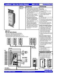
WTP-4408 Eight Output Time/Photo Controller<br />
WPS-5527K<br />
Photo Sensor<br />
(optional)<br />
Thu 15, Nov 2007<br />
2 : 45 : 33 pm<br />
Light Level: 110fc<br />
SETUP SCHED MANU INFO<br />
N<br />
12<br />
Sunny<br />
Skylight/<br />
Windows<br />
Sensor<br />
Cloudy<br />
Day<br />
Late Night<br />
9<br />
12<br />
3<br />
AM<br />
6<br />
9<br />
9<br />
3<br />
PM<br />
6<br />
12<br />
3<br />
PM<br />
6<br />
9<br />
12<br />
3<br />
PM<br />
6<br />
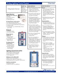
PHOTO BASED CONTROLS<br />
<br />
<br />
The optional WPS-5527K Remote Sensor is used to<br />
monitor the true measured ambient light level and is<br />
ideal for situations requiring accurate light level<br />
switching, such as skylit areas or exterior signs.<br />
Each of the WTP-4408's eight outputs can be<br />
programmed to switch at specific, user-adjustable light<br />
levels. Different light levels can be set for each output.<br />
ASTRO BASED CONTROLS<br />
<br />
Sunset<br />
Sunrise<br />
Exterior lights can be switched ON and OFF<br />
astronomically. Astronomic control in association with<br />
time based control offers the ideal combination of<br />
convenience and savings for your facility.<br />
TIME BASED CONTROLS<br />
<br />
<br />
Time-based control systems are the most cost<br />
effective method of ensuring that interior lights<br />
are OFF when the facility is not occupied.<br />
Multi-channel time clocks offer the designer<br />
the convenience of creating unique schedules<br />
for different areas. Different time-based OFF<br />
sweeps can be provided for general office<br />
areas, corridors, common areas, lobbies or<br />
different tenant spaces.<br />
Components <strong>WLCP</strong>-<strong>36WST</strong>-<strong>S3</strong> 1.1<br />
page 7<br />
lighting controls
<strong>WLCP</strong>-<strong>36WST</strong>-<strong>S3</strong><br />
WTP-4408 Controller<br />
Introduction<br />
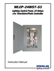
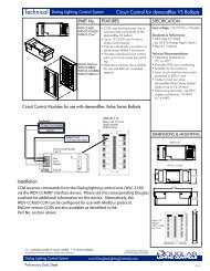
WPS-5527K Remote<br />
Sensor Head<br />
(optional)<br />
Point Sensor to Northern sky for<br />
the most consistent readings.<br />
Connect Sensor, if used, to only<br />
one Photo Controller.<br />
N<br />
WTP-4408 Photo/Time Controller<br />
Easy to program with built-in display and membrane keypad.<br />
Eight independent outputs for switching relays directly or<br />
groups of relays via scanners.<br />
Manual override.<br />
Automatic Daylight Savings.<br />
64 Holiday dates.<br />
Manual override.<br />
Astronomic and sentry switch options.<br />
Accurate switching at specific light levels for each output when<br />
using remote sensor. Range: 0-6,000 footcandles.<br />
Thu 15, Nov 2007<br />
2 : 45 : 33 pm<br />
Light Level: 110fc<br />
SETUP SCHED MANU INFO<br />
2-Wire LED Switch<br />
LED indicator push button switch for<br />
Douglas 2-wire relays and switch inputs.<br />
Can operate in parallel with a WTP-4408<br />
output.<br />
Can provide convenient manual control for<br />
each output.<br />
LEDs show status of the connected relay or<br />
input. Red LED indicates ON and green LED<br />
indicates OFF.<br />
WPS-5527K<br />
WR-8501<br />
WTP-4408<br />
WT2-Wire HID Relays (Panel Mounted)<br />
A WTP-4408 output can directly control Douglas panel-mounted<br />
2-wire relays. (WR-6161, WR-6162 or WR-6172)<br />
Each output can directly control up to 4 relays.<br />
The relays are suitable for all types of lighting<br />
loads including capacitor-corrected HID ballasts.<br />
2-wire latching relay technology.<br />
Manual override lever & ON/OFF indicator built<br />
into each relay.<br />
Operable with remote switches.<br />
WR-6161<br />
Relay<br />
Panel<br />
Components <strong>WLCP</strong>-<strong>36WST</strong>-<strong>S3</strong> 1.1<br />
page 8<br />
lighting controls
<strong>WLCP</strong>-<strong>36WST</strong>-<strong>S3</strong><br />
WTP-4408 Controller<br />
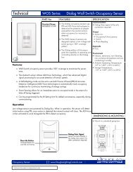
Description<br />
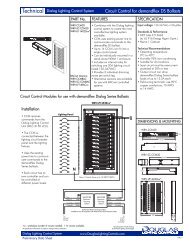
LCD Display<br />
In normal operating mode, shows the<br />
present time and (if sensor used) light level<br />
reading.<br />
In other modes, shows various prompts to<br />
guide in viewing and editing programs.<br />
WPS-5527K<br />
Remote Sensor<br />
Point to the Northern<br />
sky for the most<br />
consistent readings.<br />
Connect sensor to<br />
only one Controller.<br />
N<br />
Wiring<br />
Wire length max:<br />
500'(150m).<br />
Use two #18AWG<br />
unshielded wires.<br />
Sensor<br />
Inputs<br />
Thu 15, Nov 2007<br />
2 : 45 : 33 pm<br />
Light Level: 110fc<br />
SETUP SCHED MANU INFO<br />
Escape<br />
Button<br />
Power<br />
Indicator<br />
Membrane Keypad<br />
Press keys to set time and<br />
enter programs and<br />
Power<br />
Inputs<br />
WTP-4408 General Description<br />
Electronic 365-Day Astronomic Time/Photo Controller for switching<br />
Douglas 2-wire relays and scanners.<br />
Fits in Douglas relay Panels on center DIN rail.<br />
Uses an LCD display and membrane keypad for programming.<br />
Optional WPS-5527K Photo Sensor permits photocell control. Each<br />
output can be programmed to have a unique light level switching point.<br />
Each output is programmed to switch ON and OFF when an event<br />
occurs. Events can be:<br />
Time Based: Lights are turned ON and OFF at specific times of day.<br />
Astro Based: Light are turned ON and OFF according to the position of<br />
the sun in the sky.<br />
Photo Based: Lights are turned ON and OFF depending to measured<br />
light level (requires WPS-5527K Photo Sensor).<br />
Combination: Lights are turned ON by Photo or Astronomic<br />
measurement and OFF by time. Conversely, lights can be<br />
switched ON by time and OFF by Photo or Astronomic.<br />
Menu<br />
Buttons<br />
Clear<br />
Button<br />
Outputs<br />
8 outputs<br />
designed to<br />
switch<br />
Douglas 2-<br />
wire relays or<br />
scanners.<br />
Programming the WTP-4408<br />
Use the membrane key pad and the LCD graphic display. Prompts<br />
appear on the display to guide you in programming the unit.<br />
Any of the relay outputs can be programmed to have (including<br />
combinations of each):<br />
-ON/OFF timed events<br />
-Sentry<br />
-Astronomical<br />
-Photometric.<br />
Up to 900 events can be scheduled in a week.<br />
Set any scheduled event for any output to run on any day of the week<br />
(Su/Mon/Tue/Wed/Th/Fri/Sat) or on any specific date or Holiday.<br />
64 Holiday dates are available.<br />
In the event of power loss, the data in the Controller's memory is<br />
retained. Programming and Setup features are retained indefinitely, and<br />
time-of-day setting is retained for 72 hours.<br />
Specifications<br />
Inputs<br />
Power: 24VAC/100mA. Class 2 low voltage device.<br />
Power rating does not include power for switching relays or scanners.<br />
Connect switches in parallel with Controller outputs for remote override<br />
switching.<br />
Optional WPS-5527K Photo Sensor. Range: 0 to 6,000 footcandles.<br />
Remote mount.<br />
Outputs<br />
Eight timer/photo controlled outputs for Douglas relays and scanners.<br />
Maximum number of relays per output: 4. Connect with #18 AWG wire.<br />
Maximum length for relay control is 500' (150m).<br />
Maximum number of scanners per output: 10. Connect with #18 AWG<br />
wire. Maximum length for scanner control is 2000' (600m).<br />
Sensor<br />
A WPS-5527K Remote Photo Sensor can connect to the Controller to<br />
provide accurate light level measurements. The WPS-5527K has a<br />
range of 0 to 6,000 footcandles +/- 5%.<br />
Each output can have a unique set of light level switching points to<br />
satisfy different requirements. A dusk-to-dawn typical setting would be<br />
20fc high level (OFF point) and a 5fc low level (ON point). An interior<br />
skylight example could be 1000fc (OFF point) and 700fc (ON point).<br />
Environment<br />
Indoors, stationary non-vibrating, non-corrosive atmosphere and noncondensing<br />
humidity.<br />
Ambient operating temperature: +32 0 F to +140 0 F (0 0 C to +60 0 C).<br />
Components <strong>WLCP</strong>-<strong>36WST</strong>-<strong>S3</strong> 1.1<br />
page 9<br />
lighting controls
<strong>WLCP</strong>-<strong>36WST</strong>-<strong>S3</strong><br />
WTP-4408 Controller<br />
Mounting<br />
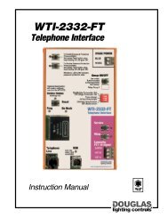
Mounting/Installation<br />
WTP-4408 Controller<br />
The WTP-4408 Photo/Timer is mounted inside the relay control panel<br />
on 35mm DIN rail.<br />
Best to locate the panel in an area that is accessible for programming<br />
the WTP-4408.<br />
Installation environment: indoors, stationary, non-vibrating, noncorrossive<br />
atmosphere and non-condensing humidity.<br />
Ambient operating temperature: +32 0 F to +140 0 F (0 0 C to +60 0 C).<br />
Optional WPS-5527K Sensor Head<br />
Do not mount the sensor where artificial light shines directly on it.<br />
For best results, mount the sensor pointing to the Northern sky.<br />
The WPS-5527K Sensor is waterproof and able to withstand harsh<br />
climate. However, when possible, mount the sensor either indoors<br />
pointing outward or in a sheltered area. The sensor's measurements<br />
will be less affected by dirt, ice or snow build-up. If mounting<br />
outdoors, try to shelter the sensor from the elements. For example,<br />
mount the sensor on the underside of the junction box (as shown in<br />
INSERT A).<br />
The sensor has a plastic mounting nipple that can be threaded to a<br />
1/2" pipe thread. A mounting nut is also supplied for mounting to a<br />
1/2" knockout.<br />
Junction Box<br />
N<br />
Sensor<br />
Wall<br />
6.5"<br />
(165)<br />
3.25"<br />
(83)<br />
12" wire<br />
(#18 AWG)<br />
9 6 2 " " & 6 E A 2 D J + J H A H<br />
Esc<br />
Power<br />
A B C D<br />
1 2 3<br />
Mo<br />
4 5 6<br />
Th<br />
7 8 9<br />
Su<br />
0<br />
Wh<br />
1<br />
Output 2<br />
Output 3<br />
Output 4<br />
Directions<br />
• Buttons A, B, C & D select options shown at Output 5<br />
the bottom of the display. Follow prompts<br />
which appears on the display to set up the<br />
unit and/or view/edit programs<br />
Output 6<br />
• Use only to control Douglas Relays or Relayt<br />
A Scanners.<br />
Output 7<br />
• For more information rfer to "Applications<br />
B & Directions" booklet or visit<br />
Output 8<br />
www.DouglasLighting Control.com<br />
White<br />
Optional WPS-5527<br />
Photo Sensor<br />
lighting controls Blue<br />
Tu<br />
Fr<br />
We<br />
Sa<br />
WPS-5527K<br />
Sensor Head<br />
WTP-4408<br />
Controller<br />
24VAC<br />
Clr<br />
Power for<br />
Outputs<br />
INSERT A<br />
35mm DIN<br />
Rail Mounting<br />
4.0"<br />
(102)<br />
1.75"<br />
(45)<br />
Components <strong>WLCP</strong>-<strong>36WST</strong>-<strong>S3</strong> 1.1<br />
page 10<br />
lighting controls
• Buttons A, B, C & D select options shown at<br />
the bottom of the display. Follow prompts<br />
which appears on the display to set up the<br />
unit and/or view/edit programs<br />
• Use only to control Douglas Relays or Relayt<br />
Scanners.<br />
• For more information rfer to "Applications<br />
& Directions" booklet or visit<br />
www.DouglasLighting Control.com<br />
<strong>WLCP</strong>-<strong>36WST</strong>-<strong>S3</strong><br />
WTP-4408 Controller<br />
Setup<br />
Planning & Initial Setup<br />
1) Fill out a working copy of the event & relay schedules.<br />
This will help guide the planning process.<br />
2) From the filled-in relay panel schedule determine which<br />
relays are connected to the same local low voltage<br />
switch and/or have the identical schedule. Connect<br />
these relays to the same relay output.<br />
CAUTION: Ensure that no more than 4 relays are<br />
connected together. A scanner will be required to switch<br />
larger quanities of relays simultaneously. Ensure that<br />
outputs are not connected together.<br />
3) Use the controller's manual (MANU) override mode to<br />
verify that the correct relay groups are being switched by<br />
the correct relay output.<br />
4) Access the SETUP menus to ensure if any of the<br />
following settings should be modified: Daylight Savings,<br />
Astro, Photocell and Sentry options.<br />
5) For Astro location information refer to Appendix A for<br />
latitude, longitude & time zone information for a variety<br />
of North American Cities. Do not use the Astro feature<br />
for latitudes above 55°N.<br />
6) Access the schedule (SCHED) menu to enter the<br />
scheduled events using the completed event schedule.<br />
See the section titled "SCHEDULING" for details.<br />
Based upon the completed panel schedule an<br />
Event Schedule can created for each relay.<br />
EVENT SCHEDULE<br />
Output #1 - Event Sequence<br />
Wall Pack<br />
A-11<br />
First employee starts at 7:30AM. Turns the Lobby & Corridor lights ON using the local low voltage switch located in the Lobby. All<br />
other lights are turned ON by local switches.<br />
Last employee leaves at 6:45PM. Turn all interior lights OFF (7:00PM) after last departure.<br />
Repeat OFF sweeps ensure that the lights are turned OFF (9PM, 11PM, 1AM, 3AM & 5AM) in case they are turned ON by a local switch.<br />
OUTPUT #1<br />
AREA CONTROLLED: Interior Lighting<br />
TIME AM/PM COMMENTS ACTION HI fc LOW fc M T W TH F SA SU<br />
7:00<br />
9:00<br />
11:00<br />
1:00<br />
3:00<br />
5:00<br />
PM<br />
PM<br />
PM<br />
AM<br />
AM<br />
AM<br />
End of the work day lights turn OFF<br />
Repeat OFF sweep<br />
Repeat OFF sweep<br />
Repeat OFF sweep<br />
Repeat OFF sweep<br />
Repeat OFF sweep<br />
OFF<br />
OFF<br />
OFF<br />
OFF<br />
OFF<br />
OFF<br />
Output #2 - Event Sequence<br />
The Photometric control feature is enabled at 5:00AM. The WTP-4408 will automatically check the measured light level from the<br />
sensor head and compare this to the Hi & Low setpoints. • If the measured light level is above Hi setpoint of 20fc, the Security lights<br />
will switch OFF. • If the measured light level is in between the Hi (20fc) & Low (5fc) no action will occur. • If the measured light level is<br />
below the Low setpoint of 5fc, the Security lights will switch ON.<br />
Throughout the course of the day the Security lights will switch ON at dusk and OFF at dawn.<br />
OUTPUT #2<br />
AREA CONTROLLED: Security<br />
TIME AM/PM COMMENTS ACTION HI fc LOW fc M T W TH F SA SU<br />
5:00 AM Photo operation enabled PHOTO ENB 20 5<br />
Output #3 - Event Sequence<br />
The Photometric control feature is enabled at 5:00AM. The WTP-4408 will automatically check the measured light level from the<br />
sensor head and compare this to the Hi & Low setpoints. • If the measured light level is above Hi setpoint of 20fc, the Security lights<br />
will switch OFF. • If the measured light level is in between the Hi (20fc) & Low (5fc) no action will occur. • If the measured light level<br />
is below the Low setpoint of 5fc, the Parking Lot lights will switch ON.<br />
Photometric control feature is disabled by an OFF command at 11:00PM. The Parking Lot & Shipping/Receiving lights will also be<br />
switched OFF.<br />
OUTPUT #3<br />
AREA CONTROLLED: Parking Lot & Shipping/Receiving Bay<br />
TIME AM/PM COMMENTS ACTION HI fc LOW fc M T W TH F SA SU<br />
5:00<br />
11:00<br />
AM<br />
PM<br />
Photo operation enabled<br />
Parking Lot lights turned OFF.<br />
Photo operation disabled.<br />
PHOTO ENB<br />
OFF<br />
20 5<br />
A-5c A-3c A-5c A-3c<br />
A-1d<br />
A-1d<br />
Sw<br />
a<br />
B B E ? A <br />
A-7a<br />
LIGHTING FLOOR PLAN<br />
Wall Pack<br />
A-11<br />
/ A A H = B B E ? A ) H A = <br />
A-3c A-5c A-3c A-5c<br />
+ H H E @ H <br />
A-1d<br />
Sw c<br />
Sw Sw<br />
B B E ? A b d<br />
Wall Pack<br />
A-11<br />
A-7b<br />
RELAY PANEL:<br />
A-1d<br />
Sw<br />
Grp<br />
Wall Pack<br />
A-11<br />
A-1d<br />
A-1d<br />
> > O <br />
A-1d<br />
Wall Pack<br />
A-11<br />
Signage<br />
A-9<br />
XYZ Company Office<br />
Pole Light<br />
A-13<br />
Pole Light<br />
A-13<br />
2 = H E C J <br />
<br />
A Panel Schedule can be created based on the<br />
Lighting Floor Plan. The schedule will indicate the<br />
level of control required for each relay plus circuit &<br />
area of control description.<br />
LCP-B<br />
Circuit Relay Interface Local Master Timer<br />
Load Description<br />
Number Number O/P Number Switch Switch Control<br />
Lobby & Corridor<br />
B-1a 1 PRS1.1 Sw-a TP-1<br />
General Office Area<br />
B-3b 2 PRS1.2 Sw-b Sw-Int TP-1<br />
General Office Area<br />
B-3c 3 PRS1.3 Sw-c Sw-Int TP-1<br />
Office #1<br />
B-5d 4 PRS1.4 Sw-d<br />
TP-1<br />
Office #2<br />
B-5e 5 PRS1.5 Sw-e<br />
TP-1<br />
Boardroom<br />
B-7f 6 PRS1.6 Sw-f<br />
TP-1<br />
Office #3<br />
B-9g 7 PRS1.7 Sw-g TP-1<br />
Office #4<br />
B-9h 8 PRS1.8 Sw-h<br />
TP-1<br />
Production/Office<br />
B-11j 9 PRS1.9 Sw-j<br />
TP-1<br />
Production/Assembly<br />
B-13k 10 PRS1.10 Sw-k Sw-Int TP-1<br />
Production/Assembly<br />
B-13m 11 PRS1.11 Sw-m Sw-Int TP-1<br />
Warehouse<br />
B-15n 12 PRS1.12 Sw-n Sw-Int TP-1<br />
Women's Washroom<br />
B-17p 13 PRS1.13 Sw-p<br />
TP-1<br />
Men's Washroom<br />
B-17q 14 PRS1.14 Sw-q<br />
TP-1<br />
Security Lighting (Wall Pack) B-19 15 PRS1.15<br />
Sw-Ext<br />
Parking Lot Lighting (Pole Light) B-21 16 PRS1.16 5 w-Ext TP-3<br />
Signage<br />
B-23 17 PRS1.17 5 w-Ext<br />
Pylon Sign<br />
B-25 18 PRS1.18 Sw-Ext TP-5<br />
Shipping/Receiving Bay B-27 19 PRS1.19<br />
Sw-Ext TP-3<br />
Spare<br />
20 PRS1.20<br />
Spare<br />
21 PRS1.21<br />
Spare<br />
22 PRS1.22<br />
Spare<br />
23 PRS1.23<br />
Spare 24 PRS1.24<br />
WTP-4408 CONTROLLER<br />
Enter the Event Schedules<br />
into the WTP-4408 memory.<br />
The schedules will operate<br />
once all events are saved &<br />
entered into memory.<br />
PANEL SCHEDULE<br />
9 6 2 " " & 6 E A 2 D J + J H A H<br />
Thurs 15, Nov 2007<br />
8:30:03 AM<br />
Light Level: 110fc<br />
SETUP SCHED MANU INFO<br />
Esc<br />
Power<br />
A<br />
B<br />
Optional WPS-5527<br />
Photo Sensor<br />
A B C D<br />
1<br />
2 3<br />
6 K<br />
4 5 6<br />
6 D<br />
. H<br />
7 8 9<br />
5 K<br />
0<br />
Directions<br />
Photocell<br />
Control<br />
9 A<br />
5 =<br />
TP-2<br />
TP-3<br />
TP-3<br />
Clr<br />
2 M A H B H<br />
K J F K J I<br />
Wh<br />
1<br />
Output 2<br />
Output 3<br />
Output 4<br />
Output 5<br />
Output 6<br />
Output 7<br />
Output 8<br />
White<br />
lighting controls Blue<br />
24VAC<br />
Astro<br />
Control<br />
TP-4<br />
TP-5<br />
Components <strong>WLCP</strong>-<strong>36WST</strong>-<strong>S3</strong> 1.1<br />
page 11<br />
lighting controls
<strong>WLCP</strong>-<strong>36WST</strong>-<strong>S3</strong><br />
Menu Tree<br />
WTP-4408 Controller<br />
Main Menu<br />
Programming<br />
Setup Menu<br />
Sched Menu<br />
(Schedule)<br />
Manu Menu<br />
(Manual)<br />
Info Menu<br />
(Information)<br />
(a) Adjust Date/Time<br />
(b) Daylight Savings<br />
(a) View/Edit Schedules<br />
(b) View/Edit Holidays<br />
(a) Override Outputs<br />
(b) Phototest 3s Mode<br />
(a) Memory Status<br />
(b) Sunset/Sunrise Time<br />
(c) Astro Settings<br />
(a) ON/OFF<br />
(c) View Event Log<br />
(b) Adjust Location<br />
(c) Adjust Dawn Offset<br />
(d) Adjust Dusk Offset<br />
(d) Photo Settings<br />
(e) Sentry Options<br />
(f) Clear Memory<br />
(a) Clear Programs<br />
(b) Clear Holidays<br />
(c) Clear Logs<br />
(d) Factory Defaults<br />
Main Menu Screen Layout<br />
Holiday Mode<br />
Indicates the WTP-4408 is<br />
currently operating a Holiday schedule<br />
Astro Enable<br />
Astro scheduled event is currently enabled<br />
Light Level Indicator<br />
Displays the current measured light<br />
level from the photo sensor. Optional<br />
photo sensor (WPS-5527) must be<br />
connected to access this feature<br />
Thurs 15, Nov 2007<br />
0 8:30:03 AM<br />
Light Level: 110fc<br />
SETUP SCHED MANU INFO<br />
A B C D<br />
Date & Time<br />
Current Date & Time are displayed<br />
Photo Enable<br />
Photo scheduled event is currently enabled<br />
Sentry Enable<br />
Sentry option is currently enabled<br />
for one of the relay outputs<br />
Daylight Savings<br />
Indicates the WTP-4408 is<br />
in daylight savings mode<br />
Menu Bar & Menu Buttons<br />
Displays various menus/options<br />
Under normal operating conditions the Main Menu Screen will always<br />
be visible. The various icons seen on the screen denote the status of<br />
a specific feature. Descriptions of all icons are shown above.<br />
After 5 minutes of inactivity in a Sub-Menu, the display will return back<br />
to the Main Menu.<br />
When power is lost, all schedules & settings are retained regardless of<br />
how long the power is absent. The time setting will be kept for a<br />
minimum of 72 hours.<br />
■ All four Sub-Menus are accessible from the Main Menu by pressing<br />
the corresponding menu buttons: A, B, C or D.<br />
Components <strong>WLCP</strong>-<strong>36WST</strong>-<strong>S3</strong> 1.1<br />
page 12<br />
Sub-Menus<br />
• SETUP (A): Setting basic parameters<br />
• SCHED (B): Schedule programming<br />
• MANU (C): Manual output override, sensor test mode<br />
• INFO (D): Display of the last 100 events performed by<br />
the controller and other information<br />
lighting controls
<strong>WLCP</strong>-<strong>36WST</strong>-<strong>S3</strong><br />
WTP-4408 Controller<br />
Programming<br />
Setup Menu<br />
Main Menu<br />
Setup Menu<br />
Sched Menu<br />
(Schedule)<br />
Manu Menu<br />
(Manual)<br />
Info Menu<br />
(Information)<br />
(a) Adjust Date/Time<br />
(b) Daylight Savings<br />
(a) View/Edit Schedules<br />
(b) View/Edit Holidays<br />
(a) Override Outputs<br />
(b) Phototest 3s Mode<br />
(a) Memory Status<br />
(b) Sunset/Sunrise Time<br />
(c) Astro Settings<br />
(a) ON/OFF<br />
(c) View Event Log<br />
(b) Adjust Location<br />
(c) Adjust Dawn Offset<br />
(d) Adjust Dusk Offset<br />
(d) Photo Settings<br />
(e) Sentry Options<br />
(f) Clear Memory<br />
(a) Clear Programs<br />
(b) Clear Holidays<br />
(c) Clear Logs<br />
(d) Factory Defaults<br />
Components <strong>WLCP</strong>-<strong>36WST</strong>-<strong>S3</strong> 1.1<br />
page 13<br />
lighting controls
<strong>WLCP</strong>-<strong>36WST</strong>-<strong>S3</strong><br />
WTP-4408 Controller<br />
Programming<br />
Setup Summary<br />
The Setup option configures most of the general settings. The following is<br />
an overview of the various Setup Sub-Menus & features that are adjustable.<br />
1 Accessing Setup Mode<br />
2<br />
From the Main Menu<br />
press the A button to<br />
access the Setup Mode<br />
option.<br />
Navigating the Setup<br />
Sub-Menus<br />
Use the A & B buttons to<br />
scroll through the various<br />
Sub-Menus within the<br />
Setup Mode.<br />
Press the D button to<br />
access the highlighted<br />
Sub-Menu.<br />
3 Sub-Menus<br />
Fri 16, Nov 2007<br />
1:00:03 AM<br />
SETUP SCHED MANU INFO<br />
A B C D<br />
SETUP MENU<br />
(a) Adjust Date/Time<br />
(b) Daylight Savings<br />
1 OF 6<br />
The Setup Menu consists of 6 Sub-Menus. The following is a description of<br />
each.<br />
OK<br />
A B D<br />
Sentry Switching - allows for any<br />
of the 8 relay outputs to be set<br />
up for sentry style switching.<br />
Default: None of the 8 relay<br />
outputs are set up for Sentry<br />
Switch control.<br />
Clear Memory - consists of 4<br />
sub menus that clear specific<br />
portions of memory:<br />
• Clear Normal Schedules<br />
• Clear Holiday Schedules<br />
• Clear Logs<br />
• Factory Reset:<br />
Restores factory defaults,<br />
clearing all types of memory<br />
including schedules & logs.<br />
Default: None.<br />
SETUP MENU<br />
(d) Photo Settings<br />
(e) Sentry Options<br />
SETUP MENU<br />
(e) Sentry Options<br />
(f) Clear Memory<br />
5 OF 6<br />
OK<br />
A B C D<br />
6 OF 6<br />
OK<br />
A B C D<br />
Adjust Date/Time - allows Date<br />
& Time to be adjusted.<br />
Default: January 12, 2001.<br />
SETUP MENU<br />
1 OF 6<br />
(a) Adjust Date/Time<br />
(b) Daylight Savings<br />
OK<br />
A B D<br />
Daylight Savings - allows for<br />
enabling & disabling of<br />
Daylight Savings. Also allows<br />
for selection of when.<br />
Default: Enabled or ON.<br />
SETUP MENU<br />
(a) Adjust Date/Time<br />
(b) Daylight Savings<br />
2 OF 6<br />
OK<br />
A B D<br />
Astro Settings - allows for<br />
enabling and disabling of<br />
Astronomic control option.<br />
Default: Disabled or OFF.<br />
Photo Settings - allows for<br />
enabling and disabling of<br />
Photocell control option.<br />
Default: Disabled or OFF.<br />
SETUP MENU<br />
(b) Daylight Savings<br />
(c) Astro Settings<br />
SETUP MENU<br />
(c) Astro Settings<br />
(d) Photo Settings<br />
3 OF 6<br />
OK<br />
A B D<br />
4 OF 6<br />
OK<br />
A B C D<br />
Components <strong>WLCP</strong>-<strong>36WST</strong>-<strong>S3</strong> 1.1<br />
page 14<br />
lighting controls
<strong>WLCP</strong>-<strong>36WST</strong>-<strong>S3</strong><br />
WTP-4408 Controller<br />
Programming<br />
Setup: Date & Time<br />
The Date & Time Setup Sub-Menu lets the user easily modify the<br />
current date & time or re-enter a new date & time.<br />
The WTP-4408 factory default Date & Time is Friday, January 12,<br />
2001 @ 1:00AM. The default Date & Time should be modified prior to<br />
normal use of the unit.<br />
During the course of entering or modifying the Date & Time, the user<br />
should be aware to go through all data entry screens, even though<br />
some entries won't need modification. Failure to do so will result in all<br />
modified data being lost & not saved to memory. The WTP-4408 will<br />
default to the last saved entry.<br />
While entering the Date & Time, if the user presses the ESC button or<br />
if there is a power failure, all the currently entered data will not be<br />
saved. The WTP-4408 will default to the last saved entry.<br />
The time is entered in AM/PM format. The WTP-4408 will<br />
automatically calculate the day of the week.<br />
From the Setup Menu select<br />
Sub-Menu (a) to adjust the<br />
date and time.<br />
SETUP MENU<br />
(a) Adjust Date/Time<br />
(b) Daylight Savings<br />
1 OF 6<br />
OK<br />
NOTE:<br />
The user MUST go<br />
through each data<br />
entry screen, even if<br />
some entries may not<br />
need modifying.<br />
This will ensure all<br />
newly entered data will<br />
be saved to memory.<br />
EDIT DATE MODE<br />
Please Enter:<br />
Day: 12<br />
EDIT DATE MODE<br />
Please Enter:<br />
Day: 15<br />
NO Correct ?<br />
A<br />
EDIT DATE MODE<br />
Please Enter:<br />
Hour: 01<br />
OK<br />
D<br />
YES<br />
D<br />
OK<br />
D<br />
1 Date/Time Adjustment<br />
Follow the on-screen prompts<br />
to adjust the date and time.<br />
The Menu Bar will help you<br />
navigate through each of the<br />
screens. Press the appropriate<br />
Menu buttons when prompted.<br />
A B D<br />
Year: 2006<br />
Month: 1 (Jan)<br />
Day: 12<br />
Time: 1:01AM<br />
EDIT<br />
D<br />
EDIT DATE MODE<br />
Please Enter:<br />
Hour: 08<br />
NO Correct ?<br />
A<br />
EDIT DATE MODE<br />
Please Enter:<br />
Min: 00<br />
YES<br />
D<br />
OK<br />
When a numeric entry is<br />
blinking use the number pad<br />
to modify the entry.<br />
Whenever the current entry<br />
is modified, the user is<br />
prompted to verify if the<br />
newly entered entry is<br />
correct.<br />
The following is a continuation<br />
of the screens the user will<br />
encounter during the course of<br />
setting up the date & time.<br />
Note that this screen will only<br />
be displayed if the current entry<br />
has been modified.<br />
EDIT DATE MODE<br />
Please Enter:<br />
Year: 2006<br />
EDIT DATE MODE<br />
Please Enter:<br />
Year: 2007<br />
NO Correct ?<br />
A<br />
EDIT DATE MODE<br />
Please Enter:<br />
Month: 01<br />
EDIT DATE MODE<br />
Please Enter:<br />
Month: 02<br />
NO Correct ?<br />
OK<br />
D<br />
YES<br />
D<br />
OK<br />
D<br />
YES<br />
The WTP-4408 Time is kept<br />
in an AM/PM format, so be<br />
sure to adjust accordingly.<br />
Press the A button for AM or<br />
the B button for PM.<br />
The Display automatically<br />
returns to the Main Menu and<br />
displays the newly entered<br />
Date & Time.<br />
EDIT DATE MODE<br />
Please Enter:<br />
Min: 30<br />
NO Correct ?<br />
A<br />
EDIT DATE MODE<br />
Please Enter:<br />
AM /PM<br />
A<br />
B<br />
Thu 15, Feb 2007<br />
8:30:03 AM<br />
D<br />
YES<br />
D<br />
OK<br />
D<br />
SETUP SCHED MANU INFO<br />
A B C D<br />
Components <strong>WLCP</strong>-<strong>36WST</strong>-<strong>S3</strong> 1.1<br />
page 15<br />
lighting controls
<strong>WLCP</strong>-<strong>36WST</strong>-<strong>S3</strong><br />
WTP-4408 Controller<br />
Programming<br />
Setup: Daylight Savings<br />
The Daylight Savings Sub-Menu lets the user enable or disable the<br />
Daylight Savings feature. When enabled the WTP-4408 will<br />
automatically adjust for Daylight Savings.<br />
The Daylight Savings option is enabled as a factory default. The<br />
default setting should be disabled if your area doesn't have Daylight<br />
Savings.<br />
As of 2007, the WTP-4408 is set up so that conversion to Daylight<br />
Savings will occur on the 2nd Monday of March and the 1st Sunday of<br />
November. For prior versions of the WTP-4408, the conversion dates<br />
are the 1st Sunday in April and the last Sunday in October. The user<br />
can change the conversion days if desired.<br />
If the user chooses to disable Daylight Savings, the display<br />
automatically returns to the Setup Menu and saves the disable setting<br />
to memory.<br />
Pressing the ESC button on<br />
the numeric keypad will cause<br />
all modified entries to revert<br />
to their orginal state and<br />
return the WTP-4408 to the<br />
Setup Menu.<br />
The following is a continuation of<br />
the screens the user will encounter<br />
during the course of setting the<br />
Daylight Savings feature.<br />
SETUP MENU<br />
(a) Adjust Date/Time<br />
(b) Daylight Savings<br />
Esc<br />
2 OF 6<br />
OK<br />
A B D<br />
From the Setup Menu select<br />
option (b) to adjust Daylight<br />
Savings.<br />
SETUP MENU<br />
(a) Adjust Date/Time<br />
(b) Daylight Savings<br />
2 OF 6<br />
OK<br />
A B D<br />
Use the A & B buttons to<br />
toggle to the month. Select<br />
the month by pressing the C<br />
button.<br />
EDIT DAYLIGHT SAVINGS<br />
STANDARD --> DAYLIGHT<br />
2nd SUNDAY in MAR<br />
OK<br />
A B C D<br />
1 Daylight Savings Adjustment<br />
Follow the screen prompts<br />
to turn Daylight Savings ON<br />
or OFF, using the A & B<br />
buttons.<br />
DAYLIGHT SAVINGS<br />
A<br />
ON / OFF<br />
B<br />
OK<br />
D<br />
By repeatedly pressing the<br />
D button, the user can view<br />
most of these screens<br />
without editing anything,<br />
return to the Setup Menu<br />
and save the last setting to<br />
memory.<br />
EDIT DAYLIGHT SAVINGS<br />
DAYLIGHT --> STANDARD<br />
1st SUNDAY in NOV<br />
OK<br />
A B C D<br />
The next screen shows the<br />
current date when Daylight<br />
Savings will occur. Using the<br />
appropriate menu buttons the<br />
user can adjust the week &<br />
month that Daylight Savings<br />
will occur.<br />
Press the A & B buttons to<br />
adjust the week Daylight<br />
Savings is to occur. The<br />
options are 1st, 2nd, 3rd,<br />
4th & last.<br />
EDIT DAYLIGHT SAVINGS<br />
STANDARD --> DAYLIGHT<br />
2nd SUNDAY in MAR<br />
OK<br />
A B C D<br />
The Main Menu will display<br />
the Daylight Savings icon<br />
whenever the Daylight<br />
Savings Mode is in effect.<br />
Thu 15, Feb 2007<br />
1:00:03 AM<br />
SETUP SCHED MANU INFO<br />
A B C D<br />
Press the C button to toggle<br />
between adjusting the week &<br />
the month.<br />
Press the D button to<br />
proceed to the next screen.<br />
Components <strong>WLCP</strong>-<strong>36WST</strong>-<strong>S3</strong> 1.1<br />
page 16<br />
lighting controls
<strong>WLCP</strong>-<strong>36WST</strong>-<strong>S3</strong><br />
WTP-4408 Controller<br />
Programming<br />
Setup: Astro Settings<br />
The Astro Settings Sub-Menu lets the user enable or disable the<br />
Astronomical feature. When this feature is enabled, the WTP-4408 can<br />
automatically calculate dusk to dawn times throughout the course of<br />
the year and use these times to switch loads ON and/or OFF.<br />
The Astro feature factory default is "disabled". This setting should be<br />
changed to "enabled" if there will be schedules using dusk and dawn<br />
times.<br />
The latitude, longitude and the time zone must be entered for the<br />
WTP-4408 to automatically calculate the dawn and dusk times. Then,<br />
the schedules that include the Astro commands will switch ON at dusk<br />
and OFF at dawn.<br />
The switching times can be offset to occur before or after the<br />
calculated dawn and dusk time. The offset can be adjusted between a<br />
range of +180 minutes to -180 minutes. The default is 0 minutes<br />
offset for both dawn and dusk.<br />
A negative offset will result in lights switching ON before dusk or OFF<br />
before dawn. Positive offset has the opposite effect, lights switching<br />
after dusk and after dawn.<br />
Refer to the Scheduling portion of this manual for a detailed description<br />
of implementing and applying the Astro feature.<br />
From the Setup Menu select<br />
option (c) to adjust the Astro<br />
Settings.<br />
1 Astro Online/Offline<br />
Follow the screen prompts to<br />
enable or disable the Astro<br />
Feature. Use the A & B<br />
buttons to turn the Astro<br />
feature ON or OFF.<br />
SETUP MENU<br />
(b) Daylight Savings<br />
(c) Astro Settings<br />
3 OF 6<br />
OK<br />
A B D<br />
ASTRONOMIC GLOBAL<br />
A<br />
ON / OFF<br />
B<br />
OK<br />
D<br />
The WTP-4408 is designed for use below 55°N Latitude and within<br />
North American Time Zones.<br />
Refer to Appendix A on pages 39-40 for a listing of North American Cities<br />
with their respective latitude, longitude & time zone.<br />
Use the number pad to enter the<br />
latitude & press the C button to<br />
change from north and south.<br />
Note: South refers to locations<br />
south of the equator.<br />
ASTRO-LOCATION SETUP<br />
ENTER YOUR LATITUDE:<br />
N 43 deg LAT<br />
N/S<br />
CAUTION: Do not enter latitude values greater than 55°N.<br />
The controller may not operate properly.<br />
Use the number pads to enter<br />
the longitude. pPress the C<br />
button to change between<br />
east and west.<br />
Use the A & B buttons to<br />
scroll through the list of<br />
available time zones to make<br />
the appropriate time zone<br />
selection.<br />
Press the D button to save the<br />
time zone selection and return to<br />
the Astro Setup Sub-Menu.<br />
C<br />
ASTRO-LOCATION SETUP<br />
ENTER YOUR LONGITUDE:<br />
W 118 deg LONG<br />
E/W<br />
C<br />
TIME ZONE SETUP<br />
SELECT YOUR TIME ZONE<br />
<br />
OK<br />
D<br />
OK<br />
D<br />
OK<br />
A B D<br />
If OFF is selected, the screen<br />
will automatically return to<br />
the Setup Menu.<br />
2 Astro Location Setup<br />
From the Astro Setup Sub-<br />
Menu select option (c), by<br />
scrolling with the A and B<br />
buttons, to adjust dawn<br />
offset time.<br />
ASTRO SETUP<br />
(b) Adjust Location<br />
(c) Adjust Dawn Offset<br />
A<br />
B<br />
3 OF 4<br />
OK<br />
Use the A & B buttons to<br />
scroll through the various<br />
screens within Astro Setup.<br />
Press the D button to<br />
access the highlighted<br />
screen.<br />
ASTRO SETUP<br />
(a) ON/OFF<br />
(b) Adjust Location<br />
1 OF 4<br />
OK<br />
A B D<br />
Use the number pads to enter<br />
the offset value. Press the C<br />
button to change between<br />
positive and negative offset.<br />
ASTRO-OFFSET SETUP<br />
Dawn Offset: +000 min<br />
LIMIT (-180min TO +180min)<br />
+/-<br />
C<br />
OK<br />
D<br />
From Astro Setup, select<br />
screen (b), using the A and B<br />
buttons, to enter location<br />
information such as latitude,<br />
longitude & time zone.<br />
ASTRO SETUP<br />
(a) ON/OFF<br />
(b) Adjust Location<br />
2 OF 4<br />
OK<br />
A B D<br />
A negative offset will result in<br />
loads switching ON before<br />
dusk and OFF before dawn.<br />
A positive offset will result in<br />
loads switching ON after dusk<br />
and OFF after dawn.<br />
Components <strong>WLCP</strong>-<strong>36WST</strong>-<strong>S3</strong> 1.1<br />
page 17<br />
lighting controls
<strong>WLCP</strong>-<strong>36WST</strong>-<strong>S3</strong><br />
WTP-4408 Controller<br />
Programming<br />
Setup: Astro Settings (continued)<br />
From the Astro Setup Sub-<br />
Menu select option (d), using<br />
the A and B buttons, to adjust<br />
dusk offset time.<br />
The procedure for adusting<br />
the dusk offset is the same as<br />
for the dawn offset: use the<br />
number pads to enter the<br />
offset value; press the C<br />
button to change between<br />
positive and negative offset.<br />
ASTRO SETUP<br />
(c) Adjust Dawn Offset<br />
(d) Adjust Dusk Offset<br />
4 OF 4<br />
OK<br />
A B D<br />
ASTRO-OFFSET SETUP<br />
Dusk Offset: +000 min<br />
LIMIT (-180min TO +180min)<br />
+/-<br />
C<br />
OK<br />
Setup: Photometric Control<br />
The Photo Settings Sub-Menu lets the user enable or disable the<br />
Photometric feature. When this feature is enabled and a WPS-5527K<br />
Photo Sensor is connected, the WTP-4408 will receive light level<br />
information from the sensor head. These readings can switch loads<br />
ON and/or OFF, depending on the setpoints selected.<br />
When installing the sensor, best results will be obtained by pointing the<br />
sensor to the northern sky.<br />
Each output can have a unique pair of light Set Points. Switching will<br />
occur only when (a) the light level passes above the the high Set Point<br />
(switches OFF) or (b) the light level passes below the low Set Point<br />
(switches ON).<br />
Refer to the Scheduling portion of this manual for a detailed description<br />
of implementing and applying the Photo feature after it is enabled.<br />
Press the Escape button on<br />
the number pad to save any<br />
modifications made with the<br />
Astro Setup Sub-Menu and<br />
return to the Setup Menu.<br />
- I ?<br />
!<br />
" # $<br />
% & '<br />
<br />
+ H<br />
Number<br />
Pad<br />
From the Setup Menu<br />
select option (d), using the<br />
A and B buttons, to enable<br />
Photo Settings.<br />
1 Photo Online/Offline<br />
SETUP MENU<br />
(c) Astro Settings<br />
(d) Photo Settings<br />
4 OF 6<br />
OK<br />
A B D<br />
The Main Menu will display<br />
the Astro Enable Icon when an<br />
Astronomic Schedule is<br />
enabled.<br />
SETUP MENU<br />
(b) Daylight Savings<br />
(c) Astro Settings<br />
Fri 12, Jan 2001<br />
1:00:03 AM<br />
3 OF 6<br />
OK<br />
A B D<br />
SETUP SCHED MANU INFO<br />
Follow the prompts to turn<br />
the Photo feature ON or<br />
OFF, using the A and B<br />
buttons.<br />
After enabling Photo<br />
Control, press the D<br />
button to return to the<br />
Setup Menu.<br />
PHOTO-CONTROL GLOBAL<br />
A<br />
ON / OFF<br />
B<br />
OK<br />
D<br />
A B C D<br />
Upon returning to the<br />
Main Menu, the Photo<br />
Enable Icon will be<br />
displayed. The Main Menu<br />
will also display the<br />
current light level reading<br />
from the sensor head.<br />
Fri 12, Jan 2001<br />
1:12:38 AM<br />
Light Level: 200 fc<br />
SETUP SCHED MANU INFO<br />
A B C D<br />
If a Photo Sensor is not<br />
connected to the<br />
Controller, the Main Menu<br />
will display 'Photohead<br />
Offline'.<br />
Thu 15, Feb 2007<br />
1:12:38 AM<br />
Photohead Offline<br />
SETUP SCHED MANU INFO<br />
A B C D<br />
Components <strong>WLCP</strong>-<strong>36WST</strong>-<strong>S3</strong> 1.1<br />
page 18<br />
lighting controls
<strong>WLCP</strong>-<strong>36WST</strong>-<strong>S3</strong><br />
WTP-4408 Controller<br />
Programming<br />
Setup: Sentry Control<br />
The outputs on the WTP-4408 can be set to provide a pulsed OFF<br />
signal for Sentry Switch Control.<br />
The factory default for the WTP-4408 is Sentry Switch Control<br />
disabled.<br />
WHAT IS SENTRY SWITCH CONTROL?<br />
Sentry switches are often used in retrofit applications to provide<br />
automated lighting control. Sentry Switches control the line voltage<br />
current (120V or 277V) to the new fixture. Whenever the power is<br />
interrupted for longer than 5 seconds, the Sentry Switch resets itself to<br />
OFF. When power is returned back ON, the fixture remains OFF<br />
because the Sentry Switch has reset to OFF. Occupants can then turn<br />
lights back ON by activating the Sentry Switch.<br />
Setup: Clear Memory<br />
The Clear Memory option has four Sub-Menus for clearing various<br />
portions of the WTP-4408 memory while leaving the others unaffected.<br />
The Clear Memory Sub-Menus include:<br />
Clear Programs: Clears all scheduled events, excluding holiday<br />
events, for all outputs.<br />
Clear Holidays: Clears all holiday dates and schedules for all<br />
outputs.<br />
Clear Logs: Clears all stored events logs from the WTP-<br />
4408 automatic event logger.<br />
Factory Defaults: Clears all stored data from memory and<br />
restores all default settings.<br />
CAUTION: Outputs that are programmed for other forms of switching<br />
such as Astronomic Control or Photo Control should NOT be<br />
programmed for Sentry Control.<br />
Only use Sentry Control in conjunction with timed OFF schedules.<br />
CAUTION: Be careful to understand the function of each of the<br />
four Sub- Menus prior to erasing any portion of memory.<br />
Once data has been erased from memory, there is no recovery<br />
mechanism to retrieve it.<br />
From the Setup Menu select<br />
option (e), using the A and B<br />
buttons, to enable Sentry<br />
Control and adjust the Sentry<br />
settings.<br />
SETUP MENU<br />
(d) Photo Settings<br />
(e) Sentry Options<br />
5 OF 6<br />
OK<br />
A B D<br />
From the Setup Menu select<br />
option (f), using the A and B<br />
buttons, to acess the Clear<br />
Memory Sub-Menus.<br />
SETUP MENU<br />
(e) Sentry Options<br />
(f) Clear Memory<br />
6 OF 6<br />
OK<br />
A B D<br />
1 Clearing Programs<br />
1 Sentry Control Setup<br />
Use the Number Keys (1-8) to<br />
select relay outputs for Sentry<br />
control.<br />
A checkmark indicates a relay<br />
output has been selected to<br />
have the Sentry control OFF<br />
pulse.<br />
Press the D button to save to<br />
memory and return to the<br />
Setup Menu.<br />
Whenever any output is<br />
enabled for Sentry Control, the<br />
Main Menu will display the<br />
Sentry Enable Icon.<br />
- I ?<br />
!<br />
" # $<br />
% & '<br />
SENTRY OUTPUTS<br />
S 1 2 3 4 5 6 7 8<br />
USE NUMBER PAD<br />
<br />
Thu 15, Feb 2007<br />
1:00:03 AM<br />
+ H<br />
Number<br />
Pad<br />
OK<br />
D<br />
SETUP SCHED MANU INFO<br />
A B C D<br />
The Clear Programs Sub-Menu will clear all regularly scheduled events<br />
(non-holiday events) from memory. If only an individual event needs to<br />
be erased, it is better to select the event through the Scheduling Menu<br />
and press the CLR button (on the keypad) to erase it.<br />
Use the A & B buttons to<br />
scroll through the various<br />
Sub-Menus.<br />
Press the D button to<br />
access the highlighted<br />
Sub-Menu.<br />
A prompt will appear to<br />
verify the deletion of the<br />
schedules. Press the A<br />
button to proceed or<br />
press the D button to<br />
cancel the action.<br />
Messages will appear<br />
indicating the status of the<br />
erasing process. After the<br />
erasing process is complete,<br />
the screen will display the<br />
Clear Memory Menu.<br />
CLEAR OPTIONS<br />
(a) Clear Programs<br />
(b) Clear Holidays<br />
1 OF 4<br />
OK<br />
A B D<br />
CLEAR PROGRAMS MENU<br />
Are you sure ???<br />
YES<br />
A<br />
CLEAR PROGRAMS MENU<br />
COMPLETE<br />
NO<br />
D<br />
Components <strong>WLCP</strong>-<strong>36WST</strong>-<strong>S3</strong> 1.1<br />
page 19<br />
lighting controls
<strong>WLCP</strong>-<strong>36WST</strong>-<strong>S3</strong><br />
WTP-4408 Controller<br />
Programming<br />
2 Clearing Holidays<br />
The Clear Holidays Sub-Menu will clear all holiday scheduled events<br />
from memory. If only an individual event needs to be erased, it is<br />
better to select the event through the Scheduling menu and press the<br />
CLR button to erase it.<br />
Use the A & B buttons to<br />
scroll through the various<br />
Sub-Menus.<br />
CLEAR OPTIONS<br />
(a) Clear Programs<br />
(b) Clear Holidays<br />
2 OF 4<br />
OK<br />
2 Factory Defaults<br />
The Factory Default Sub-Menu will erase everything and will restore all<br />
the factory default settings for the WTP-4408. The Factory Default<br />
Option does all the functions of the three other clearing menus, in<br />
addition to restoring all the factory settings to their defaults.<br />
This menu option should be used with extreme caution. The user<br />
should first note all regional settings, i.e.: latitude, longitude & time<br />
zone information. As well, all program schedules may need to be<br />
documented for future reference.<br />
Press the D button to<br />
access the highlighted<br />
Sub-Menu.<br />
A B D<br />
Use the A & B buttons to<br />
scroll through the various<br />
Sub-Menus.<br />
CLEAR OPTIONS<br />
(c) Clear Logs<br />
(d) Factory Defaults<br />
4 OF 4<br />
OK<br />
A prompt will appear to<br />
verify the deletion of the<br />
schedules. Press the A<br />
button to proceed or<br />
press the D button to<br />
cancel the action.<br />
Messages will appear<br />
indicating the status of the<br />
erasing process. Once the<br />
erasing process is complete,<br />
the screen will display the<br />
Clear Memory Menu.<br />
3 Clearing Logs<br />
CLEAR HOLIDAYS MENU<br />
Are you sure ???<br />
YES<br />
A<br />
CLEAR HOLIDAYS MENU<br />
COMPLETE<br />
The Clear Logs Sub-Menu will clear all stored logs from the event log<br />
memory. The event logger logs the last 100 events. Therefore, only<br />
the last 100 events are viewable.This is very useful for monitoring the<br />
status of the outputs over a period of time. For more information on<br />
event logging, refer to the Information section of this manual.<br />
Use the A & B buttons to<br />
scroll through the various<br />
Sub-Menus.<br />
Press the D button to<br />
access the highlighted<br />
Sub-Menu.<br />
A prompt will appear to<br />
verify the deletion of the<br />
event log. Press the A<br />
button to proceed or<br />
press the D button to<br />
cancel the action.<br />
Messages will appear<br />
indicating the status of the<br />
erasing process. After the<br />
erasing process is complete,<br />
the screen will display the<br />
Clear Memory Menu.<br />
CLEAR OPTIONS<br />
(b) Clear Holidays<br />
(c) Clear Logs<br />
NO<br />
D<br />
3 OF 4<br />
OK<br />
A B D<br />
CLEAR LOGS MENU<br />
Are you sure ???<br />
YES<br />
A<br />
CLEAR LOGS MENU<br />
Clearing Logs<br />
Please Wait...<br />
Components <strong>WLCP</strong>-<strong>36WST</strong>-<strong>S3</strong> 1.1<br />
page 20<br />
NO<br />
D<br />
Press the D button to<br />
access the highlighted<br />
Sub-Menu.<br />
A prompt will appear to<br />
verify the deletion. Press<br />
the A button to proceed<br />
or press the D button to<br />
cancel the action.<br />
Various messages will<br />
appear indicating the<br />
status of the erasing<br />
process. After the erasing<br />
process is complete, the<br />
screen will display the<br />
Clear Memory Menu.<br />
A B D<br />
FACTORY RESET<br />
Are you sure ???<br />
YES<br />
A<br />
CLEAR HOLIDAYS MENU<br />
COMPLETE<br />
Initialize WTP-4408<br />
With Defaults<br />
Clear EEprom Memory<br />
Status 30%<br />
Initialize WTP-4408<br />
With Defaults<br />
Writing Config Data<br />
Status 40%<br />
Initialize WTP-4408<br />
With Defaults<br />
Setting<br />
Default Time<br />
Thu 15, Jan 2007<br />
1:00:00 AM<br />
NO<br />
D<br />
SETUP SCHED MANU INFO<br />
A B C D<br />
lighting controls
<strong>WLCP</strong>-<strong>36WST</strong>-<strong>S3</strong><br />
WTP-4408 Controller<br />
Programming<br />
Scheduling Menu<br />
Main Menu<br />
Setup Menu<br />
Sched Menu<br />
(Schedule)<br />
Manu Menu<br />
(Manual)<br />
Info Menu<br />
(Information)<br />
(a) Adjust Date/Time<br />
(b) Daylight Savings<br />
(a) View/Edit Schedules<br />
(b) View/Edit Holidays<br />
(a) Override Outputs<br />
(b) Phototest 3s Mode<br />
(a) Memory Status<br />
(b) Sunset/Sunrise Time<br />
(c) Astro Settings<br />
(a) ON/OFF<br />
(c) View Event Log<br />
(b) Adjust Location<br />
(c) Adjust Dawn Offset<br />
(d) Adjust Dusk Offset<br />
(d) Photo Settings<br />
(e) Sentry Options<br />
(f) Clear Memory<br />
(a) Clear Programs<br />
(b) Clear Holidays<br />
(c) Clear Logs<br />
(d) Factory Defaults<br />
Components <strong>WLCP</strong>-<strong>36WST</strong>-<strong>S3</strong> 1.1<br />
page 21<br />
lighting controls
<strong>WLCP</strong>-<strong>36WST</strong>-<strong>S3</strong><br />
WTP-4408 Controller<br />
Programming<br />
Regular & Holiday Schedules<br />
There are two type of schedules - Regular & Holiday.<br />
• Regular Schedules<br />
Operate year round on a weekly basis.<br />
• Holiday Schedules<br />
Operate on a specific date and have precedence over regular<br />
schedules that repeat each week. Each holiday has its own<br />
independent schedule, allowing unique schedules for each holiday date.<br />
Regular and holiday schedules both provide the same type of scheduling<br />
features. The process of setting up a regular or a holiday schedule is<br />
virtually identical. All the same programming features are available to<br />
both, the only difference is holiday schedules operate on a specific date.<br />
• Memory Capacity<br />
The WTP-4408 controller can store up to 900 unique scheduled<br />
events. This is more than sufficient for most applications.<br />
• Power Failure<br />
Both Regular & Holiday schedules are retained indefinitely should<br />
power be disconnected to the unit. In the event of a power failure, the<br />
date and time are retained for a period of 72 hrs. If more than 72 hours<br />
elapses, date and time must be manually restored. All programmed<br />
Schedules, though, are saved indefinitely if power is lost.<br />
Scheduling Basics<br />
The Scheduling Option lets the user enter both weekly and holiday<br />
scheduled events into the WTP-4408 memory. The following is a guide<br />
on how to set up all the various types of schedules.<br />
The procedure for creating or editing a weekly or holiday schedule is<br />
virtually identical, except that holiday schedules require the user to<br />
enter a specific date on which the schedule will be executed.<br />
Most of the examples and explanations depicted in this section are<br />
those for a weekly schedule.<br />
1 Accessing Schedule Mode<br />
2<br />
From the Main Menu<br />
press the B button to<br />
access Schedule<br />
Mode.<br />
Thu 15, Feb 2007<br />
8:30:03 AM<br />
Light Level: 110fc<br />
SETUP SCHED MANU INFO<br />
A B C D<br />
Navigating the Schedule Sub Menus<br />
3 Creating Holiday Schedules<br />
The following pages describe how to enter a schedule into the WTP-<br />
4408. There are two types of schedules the WTP-4408 can<br />
accommodate - weekly and holiday. Holiday schedules operate on a<br />
specific day of the year rather than year round like a weekly schedule.<br />
Shown below are the different screens a user will encounter when<br />
setting up a holiday schedule as opposed to a weekly schedule.<br />
From the Schedule Menu<br />
select option (b), using the<br />
A and B buttons, to enter a<br />
holiday schedule.<br />
The display will indicate if<br />
any holiday schedules are<br />
present. Press A & B buttons<br />
to scroll through the<br />
available holiday dates.<br />
Press the C button to<br />
edit the highlighted<br />
holiday date.<br />
Press the D button<br />
to create a new<br />
holiday schedule.<br />
These screens depict a new<br />
holiday schedule being<br />
created.<br />
Press A button to select<br />
entering the month and<br />
the B button to select<br />
entering the day.<br />
Use the number buttons<br />
on the keypad to enter<br />
the month and day of the<br />
holiday.<br />
Press the D button to save<br />
the holiday date and to set<br />
up scheduled events.<br />
SCHEDULE MENU<br />
(a) View/Edit Sched's<br />
(b) View/Edit Holiday<br />
VIEW/EDIT HOLIDAYS<br />
No Holidays<br />
in Memory<br />
2 OF 2<br />
OK<br />
A B D<br />
NEW<br />
A B D<br />
OR<br />
VIEW/EDIT HOLIDAYS<br />
> Jan 1<br />
> Dec 25<br />
EDIT<br />
NEW HOLIDAY<br />
MONTH<br />
01<br />
A<br />
B<br />
NEW<br />
A B C D<br />
DAY<br />
01<br />
OK<br />
D<br />
Use the A & B buttons to<br />
scroll through the various<br />
Sub-Menus within the<br />
Scheduling Menu.<br />
Press the D button to<br />
access the highlighted<br />
Sub-Menu.<br />
SCHEDULE MENU<br />
(a) View/Edit Sched's<br />
(b) View/Edit Holiday<br />
1 OF 2<br />
OK<br />
A B D<br />
Components <strong>WLCP</strong>-<strong>36WST</strong>-<strong>S3</strong> 1.1<br />
page 22<br />
Use the number keypad to<br />
select the desired output.<br />
The steps for creating a holiday schedule<br />
are identical to those for creating a weekly<br />
schedule. Refer to the following pages for<br />
programming a weekly schedule.<br />
VIEW/EDIT OUTPUT<br />
Holiday: Jan 01<br />
Select Output: ?<br />
Using Number Pad<br />
lighting controls
<strong>WLCP</strong>-<strong>36WST</strong>-<strong>S3</strong><br />
WTP-4408 Controller<br />
Programming<br />
Types Of Schedules<br />
1 Timed Schedules<br />
Use timed schedules to automatically switch lights.<br />
Remote switches permit occupant ON/OFF switching.<br />
1 2 3<br />
9<br />
12<br />
3<br />
AM<br />
6<br />
At opening,<br />
lights ON (see NOTE)<br />
12<br />
PM<br />
9<br />
6<br />
3<br />
After close<br />
Scheduled OFF<br />
12<br />
PM<br />
9<br />
6<br />
3<br />
Late night<br />
Repeat OFF<br />
NOTE:<br />
If local switches are installed,<br />
ON schedules should not be<br />
used, because the switches<br />
permit the lights to be turned<br />
ON only when needed. OFF<br />
schedules should be used,<br />
though, to ensure lights are<br />
eventually switched OFF.<br />
2 Astronomical Control<br />
Using longitude, latitude, time zone and date, the controller<br />
calculates the sunset and sunrise times. Outputs can be<br />
programmed to switch at these calculated times.<br />
An offset time (± 180 min) can be entered to cause the switching<br />
to occur before or after the actual sunset and sunrise times.<br />
Day<br />
Parking<br />
Lights<br />
Wall<br />
Packs<br />
Dusk<br />
Late<br />
Night<br />
Dawn<br />
Parking lot and building<br />
security lights ALL OFF.<br />
Switch exterior<br />
lights ALL ON.<br />
Switch parking lot OFF,<br />
leave wall packs ON.<br />
Before dawn, parking can<br />
go back ON (not shown).<br />
At dawn, ALL OFF.<br />
3 Photometric Control<br />
<br />
Connecting WPS-5527K Photo Sensor to the WTP-4408<br />
controller permits digital entry of the light levels.<br />
Range of sensor: 0-6000 foot candles.<br />
Each output of the controller can have unique ON and<br />
OFF set points for the different requirements of each<br />
of the lighting loads.<br />
Sunny Cloudy Night Night<br />
Sensor<br />
Skylight/<br />
Windows<br />
Timed OFF<br />
12<br />
9<br />
6<br />
3<br />
When sunny, interior<br />
lights near window or<br />
skylights can be OFF.<br />
When overcast, interior<br />
lights near window or<br />
skylights are turned ON.<br />
When dark, interior<br />
lights near window or<br />
skylights are turned ON.<br />
Time control can be used<br />
to switch lights OFF and<br />
to disable sensor effect.<br />
Components <strong>WLCP</strong>-<strong>36WST</strong>-<strong>S3</strong> 1.1<br />
page 23<br />
lighting controls
<strong>WLCP</strong>-<strong>36WST</strong>-<strong>S3</strong><br />
WTP-4408 Controller<br />
Programming<br />
Scheduling Flow Chart<br />
Scheduling Sub-Menu.<br />
Press B Button.<br />
View/Edit/Create<br />
Weekly Schedules.<br />
Select Option (a).<br />
View/Edit/Create<br />
Holiday Schedules.<br />
Select Option (b).<br />
Select or Create a<br />
New Holiday Date.<br />
Select Output Number.<br />
Use Number Button on Keypad.<br />
Edit a Selected Schedule.<br />
Press C Button.<br />
Create a New Schedule.<br />
Press D Button.<br />
Enter Time.<br />
Press A Button.<br />
Enter Output Action Type.<br />
Press B Button.<br />
Select the Days of the Week<br />
the Schedule will operate.<br />
Press C Button.<br />
NOTE:<br />
Day of the Week Selection is not<br />
available for Holiday Schedules<br />
Save the Schedule<br />
to Static Memory.<br />
Press D Button.<br />
Save to Permanent Memory.<br />
Press ESC Button on Keypad<br />
until Main Menu is visible.<br />
Components <strong>WLCP</strong>-<strong>36WST</strong>-<strong>S3</strong> 1.1<br />
page 24<br />
lighting controls
<strong>WLCP</strong>-<strong>36WST</strong>-<strong>S3</strong><br />
Lighting Control Design - Office/Warehouse Complex Example<br />
It is recommended to use the following design example as a guide for<br />
utilizing the various features of the WTP-4408 and setting up schedules.<br />
ABC Company Office<br />
Wall Pack<br />
B-19<br />
Wall Pack<br />
B-19<br />
Wall Pack<br />
B-19<br />
Wall Pack<br />
B-19<br />
9 = H A D K I A <br />
2 H @ K ? J E B B E ? A<br />
<br />
<br />
B-11j<br />
B-5e<br />
B-5d<br />
B-15n<br />
B-15n<br />
B-15n<br />
n Sw<br />
Sw<br />
j<br />
e<br />
Sw<br />
B B E ? A <br />
B B E ? A <br />
Sw<br />
d<br />
Pole Light<br />
5 D E F F E C 4 A ? A E L E C * = O B-27<br />
B-1a<br />
B-1a<br />
Wall Pack<br />
B-19<br />
2 H @ K ? J E ) I I A <br />
Sw k, m<br />
* = H @ H <br />
B-7f<br />
Wall Pack<br />
B-19<br />
B-13k B-13m B-13k<br />
B-13m B-13k B-13m<br />
B-13k B-13m B-13k<br />
B-7f<br />
Sw<br />
Int, Ext<br />
WTP-4408 Controller<br />
B-7f<br />
B-9g<br />
> O <br />
B-3c B-3c B-3c<br />
<br />
A I <br />
9 A I <br />
B B E ? A ! B B E ? A " <br />
B-9h<br />
B-17q<br />
B-17q<br />
B-17p<br />
B-17p<br />
Sw f Sw g Sw h<br />
q<br />
Sw<br />
Sw<br />
p<br />
Programming<br />
Electrical lighting plan for ABC<br />
Company office building<br />
Control Strategy:<br />
• Interior Lights are to be controlled<br />
by local low voltage switches. An<br />
interior master override switch<br />
located in the General Office Area will<br />
override the General Office Area, the<br />
Production/Assembly, and the<br />
Warehouse lighting ON or OFF. The<br />
WTP-4408 will automatically sweep<br />
the lights OFF in the evening and late<br />
night.<br />
• Exterior Lights are to be controlled<br />
by the photocell and all the<br />
signage to be controlled by the<br />
WTP-4408's Astro feature. Only<br />
the wall pack & pylon sign will<br />
remain ON past 11PM each day.<br />
Circuit Number and<br />
Switch Leg information<br />
Low Voltage Switch<br />
with Switch Leg information<br />
B-1a<br />
Sw<br />
a<br />
B-1a<br />
Sw<br />
b, c<br />
/ A A H = B B E ? A ) H A =<br />
> > O<br />
B-3b B-3b B-3b<br />
B-1a<br />
B-1a<br />
Signage<br />
B-23<br />
Pole Light<br />
B-21<br />
2 = H E C J<br />
Pole Light<br />
B-21<br />
LEGEND<br />
Low Bay Fixture<br />
Pot Light Fixture<br />
B-9g<br />
Fluorescent Fixture<br />
Sw<br />
Low Voltage Switch<br />
Pylon Sign<br />
B-25<br />
Components <strong>WLCP</strong>-<strong>36WST</strong>-<strong>S3</strong> 1.1<br />
page 25<br />
lighting controls
<strong>WLCP</strong>-<strong>36WST</strong>-<strong>S3</strong><br />
WTP-4408 Controller<br />
Programming<br />
Design Notes:<br />
• The relay panel will contain a WTP-4408 for Photo, Astro & Timed events.<br />
• The relay panel will also contain a WRS-2224 Programmable Relay Scanner.<br />
The WRS-2224 will allow for groups of relays to be switched simultaneously.<br />
The scanner comes with 24 outputs (1 output per relay) and 5 inputs. Any of<br />
the 5 inputs can control any combination of the 24 outputs.<br />
The Relay Panel consists of:<br />
• 1 hinged locking relay cabinet.<br />
• 1 WR-4075-120/277<br />
Transformer.<br />
• 36 WR-6161 Douglas 2-wire<br />
latching HID relays.<br />
• 1 WTP-4408 Photo/Time<br />
Controller.<br />
RELAY PANEL:<br />
LCP-B<br />
• 1 WRS-2224 Programmable<br />
Relay Scanner.<br />
Load Description<br />
Circuit<br />
Number<br />
Relay<br />
Number<br />
Interface<br />
O/P Number<br />
Local<br />
Switch<br />
Master<br />
Switch<br />
Timer<br />
Control<br />
Photocell<br />
Control<br />
Astro<br />
Control<br />
Lobby & Corridor<br />
General Office Area<br />
General Office Area<br />
B-1a<br />
B-3b<br />
B-3c<br />
1<br />
2<br />
3<br />
PRS1.1<br />
PRS1.2<br />
PRS1.3<br />
Sw-a TP-1<br />
Sw-b Sw-Int TP-1<br />
Sw-c Sw-Int TP-1<br />
Relay Panel schedule<br />
generated from the<br />
electrical lighting plan<br />
Office #1<br />
B-5d<br />
4<br />
PRS1.4<br />
Sw-d<br />
TP-1<br />
Office #2<br />
B-5e<br />
5<br />
PRS1.5<br />
Sw-e<br />
TP-1<br />
Boardroom<br />
B-7f<br />
6<br />
PRS1.6<br />
Sw-f<br />
TP-1<br />
Office #3<br />
B-9g<br />
7<br />
PRS1.7<br />
Sw-g<br />
TP-1<br />
Office #4<br />
B-9h<br />
8<br />
PRS1.8<br />
Sw-h<br />
TP-1<br />
Production/Office<br />
B-11j<br />
9<br />
PRS1.9<br />
Sw-j<br />
TP-1<br />
Production/Assembly<br />
B-13k<br />
10<br />
PRS1.10<br />
Sw-k Sw-Int TP-1<br />
Production/Assembly<br />
Warehouse<br />
Women's Washroom<br />
Men's Washroom<br />
B-13m<br />
B-15n<br />
B-17p<br />
B-17q<br />
11<br />
12<br />
13<br />
14<br />
PRS1.11<br />
PRS1.12<br />
PRS1.13<br />
PRS1.14<br />
Sw-m Sw-Int TP-1<br />
Sw-n Sw-Int TP-1<br />
Sw-p TP-1<br />
Sw-q TP-1<br />
• "TP-1"<br />
Photo/Timer<br />
(WTP-4408)<br />
output number #1<br />
Security Lighting (Wall Pack)<br />
B-19<br />
15<br />
PRS1.15<br />
Sw-Ext<br />
TP-2<br />
Parking Lot Lighting (Pole Light)<br />
B-21<br />
16<br />
PRS1.16<br />
Sw-Ext<br />
TP-3<br />
TP-3<br />
Signage<br />
B-23<br />
17<br />
PRS1.17<br />
Sw-Ext<br />
TP-4<br />
Pylon Sign<br />
B-25<br />
18<br />
PRS1.18<br />
Sw-Ext<br />
TP-5<br />
TP-5<br />
Shipping/Receiving Bay<br />
B-27<br />
19<br />
PRS1.19<br />
Sw-Ext<br />
TP-3<br />
TP-3<br />
Spare<br />
Spare<br />
Spare<br />
20<br />
21<br />
22<br />
PRS1.20<br />
PRS1.21<br />
PRS1.22<br />
• "Sw-Ext"<br />
low voltage switch Ext<br />
(exterior).<br />
Spare<br />
Description & circuit number<br />
from the lighting plan<br />
23<br />
PRS1.23<br />
Spare 24 PRS1.24<br />
Components <strong>WLCP</strong>-<strong>36WST</strong>-<strong>S3</strong> 1.1<br />
page 26<br />
Low Voltage Controls<br />
Refer the next page for the completed Event Schedules<br />
• "PRS1.24"<br />
Programmable Relay<br />
Scanner (WRS-2224)<br />
unit number #1 and<br />
output number #24.<br />
lighting controls
<strong>WLCP</strong>-<strong>36WST</strong>-<strong>S3</strong><br />
WTP-4408 Controller<br />
Programming<br />
Time Clock Event Schedules - Office/Warehouse Complex Example<br />
Each utilized WTP-4408 Output requires an event schedule indicating the type of event and when the event will occur. Refer to Appendix B for<br />
blank Event Schedules. Completing these schedules will help organize and greatly ease the programming process. The following are completed<br />
Event Schedules for the sample office/warehouse building for ABC Company on the previous pages.<br />
Output #1 - Event Sequence<br />
Clock does not turn the lights ON. Instead, entrance lights are switched ON by the first employee who uses the switch station<br />
located in the lobby. All other lights are also turned ON by local switches.<br />
Last employee leaves at 6:45 PM. Clock turns all interior lights OFF (7:00 PM) if any were left ON.<br />
■ Repeat OFF sweeps ensure that the lights are turned OFF (9 PM, 11 PM, 1 AM, 3 AM & 5 AM) in case they were turned ON at<br />
a local switch (for example, by a janitor).<br />
OUTPUT: #1 AREA CONTROLLED: Interior Lighting<br />
TIME AM/PM COMMENTS ACTION HI fc LOW fc M T W TH F SA SU<br />
7:00 PM End of the work day. Lights turn OFF OFF<br />
9:00 PM Repeat OFF sweep<br />
OFF<br />
11:00 PM Repeat OFF sweep<br />
OFF<br />
1:00<br />
AM<br />
Repeat OFF sweep<br />
OFF<br />
3:00<br />
AM<br />
Repeat OFF sweep<br />
OFF<br />
5:00<br />
AM<br />
Repeat OFF sweep<br />
OFF<br />
Output #2 - Event Sequence<br />
The Photometric control feature is enabled at 5:00 AM. The WTP-4408 will automatically check the measured light level<br />
from the sensor head and compare it to the high & low setpoints.<br />
• If the measured light level is above high setpoint of 20fc, the Security lights will switch OFF.<br />
• If the measured light level is in between the high (20fc) and low (5fc) setpoints, no action will occur.<br />
• If the measured light level is below the low setpoint of 5fc, the Security lights will switch ON.<br />
The Security lights will switch ON at dusk and OFF at dawn or whenever the light level crosses one of the thresholds..<br />
OUTPUT: #2 AREA CONTROLLED: Security<br />
TIME AM/PM COMMENTS ACTION HI fc LOW fc M T W TH F SA SU<br />
5:00 AM Photo operation enabled PHOTO ENB 20 5<br />
Components <strong>WLCP</strong>-<strong>36WST</strong>-<strong>S3</strong> 1.1<br />
page 27<br />
lighting controls
<strong>WLCP</strong>-<strong>36WST</strong>-<strong>S3</strong><br />
WTP-4408 Controller<br />
Programming<br />
Output #3 - Event Sequence<br />
The Photometric control feature is enabled at 5:00 AM. The WTP-4408 will automatically check the measured light<br />
level from the sensor head and compare it to the high and low setpoints.<br />
• If the measured light level is above the high setpoint of 20fc, the Parking Lot lights will switch OFF.<br />
• If the measured light level is in between the high (20fc) and low (5fc) setpoints, no action will occur.<br />
• If the measured light level is below the low setpoint of 5fc, the Parking Lot lights will switch ON.<br />
Photometric control feature is disabled by an OFF command at 11:00PM. The Parking Lot & Shipping/Receiving lights<br />
will be switched OFF.<br />
OUTPUT: #3 AREA CONTROLLED: Parking Lot & Shipping/Recieving Bay<br />
TIME AM/PM COMMENTS ACTION HI fc LOW fc M T W TH F SA SU<br />
5:00<br />
AM<br />
Photo operation enabled.<br />
Parking Lot lights turned OFF.<br />
Photo operation disabled.<br />
PHOTO ENB<br />
20 5<br />
nce<br />
11:00<br />
PM<br />
OFF<br />
Output #4 - Event Sequence<br />
The Astronomic control feature is enabled at 5:00 AM. The WTP-4408 will automatically check to see if the last event<br />
was sunrise or sunset. The Signage will be switched OFF or ON, depending on the last event. On most dates throughout<br />
the course of the year the last event would be sunset, so the Signage will turn ON.<br />
Sunrise occurs. The Signage lights will be switched OFF.<br />
Sunset occurs later on that same day and the Signage lights are switched ON.<br />
OUTPUT: #4 AREA CONTROLLED: Signage<br />
TIME AM/PM COMMENTS ACTION HI fc LOW fc M T W TH F SA SU<br />
5:00 AM Astro operation enabled ASTRO ENB<br />
Output #5 - Event Sequence<br />
The Astronomic control feature is enabled at 5:00 AM. The WTP-4408 will automatically check to see if the last event<br />
was sunrise or sunset. The Pylon Signs will be switched OFF or ON, depending on the last event. on most dates<br />
throughout the course of the year the last event would be sunset, so the Pylon Signs will turn ON.<br />
Sunrise occurs. The Pylon Sign lights are switched OFF.<br />
■ Sunset occurs later on that same day and the Pylon Sign lights are switched ON.<br />
Astronomic control feature is disabled by an OFF command at 11:00 PM. The Pylon Sign lights will also be switched OFF.<br />
OUTPUT: #5 AREA CONTROLLED: Pylon Signs<br />
TIME AM/PM COMMENTS ACTION HI fc LOW fc M T W TH F SA SU<br />
5:00<br />
AM<br />
Astro operation enabled.<br />
Pylon Signage turned OFF.<br />
Astro operation disabled.<br />
ASTRO ENB<br />
11:00<br />
PM<br />
OFF<br />
Components <strong>WLCP</strong>-<strong>36WST</strong>-<strong>S3</strong> 1.1<br />
page 28<br />
lighting controls
<strong>WLCP</strong>-<strong>36WST</strong>-<strong>S3</strong><br />
WTP-4408 Controller<br />
Programming<br />
Programming a Schedule<br />
Scheduled events must be programmed for each relay output used.<br />
There are four components that make up a scheduled event:<br />
• Time - This is the time of day when the scheduled event will<br />
occur. Time is entered in AM/PM format.<br />
• Action - Can be chosen from one of the following; ON, OFF,<br />
OFF+Flick, Time Out, Photocell, Astronomic or No Action.<br />
• Days - Specific days, or all days, of the week can be selected to<br />
execute the scheduled event. (NOTE: this option not available<br />
when programming a holiday schedule).<br />
• Save - A scheduled event is saved to temporary memory.<br />
Scheduled events are saved to permanent memory once the user<br />
returns back to the Main Menu.<br />
Use the following section as a guide for setting up all types of scheduled<br />
events.<br />
From the Schedule Menu select<br />
option (a), using the A and B<br />
buttons, to create a new<br />
Weekly scheduled event.<br />
Use the number keys on the<br />
keypad to select the desired<br />
relay output (1 through 8).<br />
The display will indicate if<br />
any scheduled events have<br />
been set up for the selected<br />
relay output.<br />
Press the A and B buttons to<br />
scroll the scheduled events.<br />
Press the C button to edit<br />
the highlighted scheduled<br />
event.<br />
Press the D button to create<br />
a new scheduled event.<br />
If the D button is pressed to<br />
create a new scheduled event,<br />
this screen will appear:<br />
SCHEDULE MENU<br />
(a) View/Edit Sched's<br />
(b) View/Edit Holiday<br />
1 OF 2<br />
OK<br />
A B D<br />
VIEW/EDIT OUTPUT<br />
Select Output: ?<br />
Using Number Pad<br />
VIEW OUTPUT: 1 MTWTFSS<br />
No Schedules<br />
For this Output<br />
NEW<br />
Highlighted Event Days of<br />
Event Action Week<br />
Selected<br />
Relay Output #<br />
VIEW OUTPUT: 1 MTWTFSS<br />
Event Time 05:00A ON MTWTF<br />
11:00P OFF MTWTFSS<br />
EDIT NEW<br />
A B C D<br />
NEW OUTPUT: 1 MTWTFSS<br />
--:--A MTWTFSS<br />
TIME<br />
ACTION<br />
OR<br />
DAYS<br />
SAVE<br />
A B C D<br />
NOTE:<br />
To cancel any modifications while editing the event, press the<br />
ESC button on the keypad to return to the Event Schedule<br />
Menu without saving any changes.<br />
Components <strong>WLCP</strong>-<strong>36WST</strong>-<strong>S3</strong> 1.1<br />
page 29<br />
1 Event Time Setup<br />
Press the A button to<br />
modify the time.<br />
Press the C button to<br />
toggle between AM<br />
and PM.<br />
Use the number keys<br />
on the keypad to enter<br />
the time.<br />
Press the D button to<br />
accept the newly<br />
entered time entry and<br />
return back to Event<br />
Schedule Menu.<br />
The Event Schedule Menu<br />
appears and displays the<br />
newly entered time for the<br />
event.<br />
2 Event Action Setup<br />
Press the B button to<br />
select the type of<br />
event Action.<br />
Press the A and B<br />
buttons to scroll<br />
through the types of<br />
event actions.<br />
The following<br />
sections explain each<br />
of the various action<br />
types that are<br />
available.<br />
NEW OUTPUT: 1 MTWTFSS<br />
--:--A MTWTFSS<br />
TIME<br />
ACTION<br />
DAYS<br />
SAVE<br />
A B C D<br />
NEW SCHEDULE TIMES:<br />
PLEASE ENTER<br />
TIME<br />
--:-- AM<br />
AM/PM OK<br />
NEW SCHEDULE TIMES:<br />
PLEASE ENTER<br />
TIME<br />
06:00 AM<br />
OK<br />
NEW OUTPUT: 1 MTWTFSS<br />
06:00A MTWTFSS<br />
TIME<br />
ACTION<br />
DAYS<br />
D<br />
SAVE<br />
A B C D<br />
NEW OUTPUT: 1 MTWTFSS<br />
06:00A MTWTFSS<br />
TIME<br />
ACTION<br />
C<br />
DAYS<br />
NEW SCHEDULE ACTION<br />
TYPE OF <br />
ACTION:<br />
SAVE<br />
A B C D<br />
OK<br />
A B D<br />
lighting controls
<strong>WLCP</strong>-<strong>36WST</strong>-<strong>S3</strong><br />
WTP-4408 Controller<br />
Programming<br />
Types of Schedules<br />
ON<br />
The relay output will issue a<br />
signal to turn the relay(s)<br />
ON at the specified time.<br />
Press the D button to<br />
confirm the ON action and<br />
return to the Event<br />
Schedule Menu.<br />
The Event Schedule Menu<br />
appears:<br />
OFF<br />
The relay output will issue a<br />
signal to turn the relay(s)<br />
OFF at the specified time.<br />
Press the D button to<br />
confirm the OFF action<br />
and return to the Event<br />
Schedule Menu.<br />
The Event Schedule Menu<br />
appears:<br />
Photocell Enable<br />
Refer to Page 28 for how<br />
to SAVE a schedule to<br />
permanent memory.<br />
NEW SCHEDULE ACTION<br />
TYPE OF <br />
ACTION: ON<br />
OK<br />
A B D<br />
NEW OUTPUT: 1 MTWTFSS<br />
06:00A ON MTWTFSS<br />
TIME<br />
ACTION<br />
DAYS<br />
SAVE<br />
A B C D<br />
NEW SCHEDULE ACTION<br />
TYPE OF ON<br />
ACTION: OFF<br />
In order to utilize this feature, a WPS-5527K Photometric Sensor<br />
must be connected to the WTP-4408 Controller and the Photo<br />
Settings Option must be turned ON in the Setup Menu.<br />
Photo control will be enabled<br />
at the specified time.<br />
Press the D button to confirm<br />
the Photocell Enable action<br />
and proceed to the Setpoint<br />
Setup screen.<br />
When the Setpoint Setup<br />
screen appears, press the A<br />
button to modify the high<br />
setpoint or the B button to<br />
modify the low setpoint.<br />
Use the number keys on the<br />
keypad to enter both the high<br />
and low level setpoints. Be<br />
sure that the high setpoint<br />
value is greater than the low.<br />
NEW SCHEDULE ACTION<br />
TYPE OF TIMEOUT ENB<br />
ACTION: PHOTO ENB<br />
OK<br />
A B D<br />
SETPOINT SETUP<br />
HIGH LEVEL:<br />
LOW LEVEL:<br />
HIGH LOW<br />
A<br />
B<br />
OK<br />
A B D<br />
NEW OUTPUT: 1 MTWTFSS<br />
06:00A OFF MTWTFSS<br />
TIME<br />
ACTION<br />
DAYS<br />
SAVE<br />
A B C D<br />
0020 fc<br />
0005 fc<br />
Components <strong>WLCP</strong>-<strong>36WST</strong>-<strong>S3</strong> 1.1<br />
page 30<br />
Photocell Enable (continued)<br />
Press the D button to<br />
confirm the Photocell<br />
Enable and the setpoint<br />
selections and return to<br />
the Event Schedule Menu.<br />
The Event Schedule Menu<br />
appears:<br />
How the Photocell Control (PHOTO ENB) works:<br />
The WTP-4408 will automatically keep track of the measured light level<br />
(in footcandles) sent from the sensor head. This information will be<br />
displayed on the Main Menu. The measured light level can be used to<br />
switch relays ON or OFF depending on the setpoints.<br />
The following diagram shows the relationship between measured light<br />
level and the setpoints.<br />
15fc<br />
current measured light level<br />
from sensor head<br />
ON<br />
5fc<br />
Low Level Setpoint<br />
Dead Band<br />
OFF<br />
20fc<br />
High Level Setpoint<br />
When the measured light level passes above the High setpoint, the relay<br />
output will turn OFF. The opposite occurs when the measured light level<br />
falls below the Low setpoint.<br />
Note the switching action only occurs when the light level goes past a<br />
setpoint or when the Photocell is enabled by a scheduled event. The relay<br />
outputs will issue a momentary signal ON or OFF.<br />
The WTP-4408 will wait 3 minutes to switch the relays. The purpose is to<br />
nullify any temporary changes to the light level that could cause false<br />
switching.<br />
Photocell control is used primarily in exterior or interior skylighting<br />
control applications. Typically, for an exterior application the setpoints<br />
would be 20fc for the High & 5fc for the Low.<br />
For an interior application that switches lights on a cloudy day, typical<br />
setpoints are 1000fc for the High and 700fc for the Low.<br />
CAUTION: Do not schedule an ON or an Astronomical (Astro ENB)<br />
event when the Photocell mode (Photo ENB) is scheduled to<br />
operate on that output.<br />
Continued on the next page ...<br />
SETPOINT A SETUP B D<br />
HIGH LEVEL:<br />
0020 fc<br />
LOW LEVEL:<br />
0005 fc<br />
OK<br />
NEW OUTPUT: 1 MTWTFSS<br />
06:00A PHOTO ENB MTWTFSS<br />
TIME<br />
ACTION<br />
DAYS<br />
D<br />
SAVE<br />
A B C D<br />
lighting controls
<strong>WLCP</strong>-<strong>36WST</strong>-<strong>S3</strong><br />
WTP-4408 Controller<br />
Programming<br />
Photocell Enable (continued)<br />
The Photocell Control can be set up to operate in several different<br />
ways, as described below.<br />
DUSK-to-DAWN - To achieve this type of control it is advised that<br />
the Photocell Control feature be enabled every day of the week. An<br />
example time would be 4:00AM. Make sure no other schedules are<br />
operating the same relay output.<br />
The relays (lights) will turn ON at Dusk and OFF at Dawn. By<br />
adjusting the High & Low setpoints the user can vary the amount of<br />
light that is required to switch the relays ON or OFF. Dusk-to-Dawn<br />
control is ideal for security lighting applications. The diagram below<br />
shows a typical Photocell Dusk-to-Dawn control cycle.<br />
Photocell Enabled, light level<br />
below Low setpoint, relays turn ON<br />
(probably already ON by dusk signal)<br />
Cycle repeats itself the<br />
following day<br />
Photocell Enable (continued)<br />
DUSK-to-TIMED OFF, TIMED ON-to-DAWN - To achieve this type of<br />
control, the Photo control is enabled at a time before dawn when the<br />
lights are to be switched ON, for instance 4:00 AM. When enabled,<br />
the Photo command will issue an ON signal before sunrise or an OFF<br />
signal after sunrise. At sunset, an ON signal is issued. Late at night,<br />
a timed OFF signal occurs to switch OFF the lights. At 4:00 AM the<br />
Photo enable occurs and the cycle repeats.<br />
By adjusting the High & Low setpoints, the user can vary the<br />
amount of light required to switch relays ON or OFF. The diagram<br />
below shows a typical Photo Sunset-to-Timed-OFF control cycle.<br />
Photo Enabled, light level below<br />
setpoint, relays turn ON<br />
Sunrise occurs,<br />
relays turn OFF<br />
Cycle repeats itself the<br />
following day<br />
Sunset occurs,<br />
relays turn ON<br />
Light level goes above High<br />
setpoint, relays turn OFF<br />
Light level goes below Low<br />
setpoint, relays turn ON<br />
OFF schedule occurs,<br />
Photo Disabled, relays<br />
turn OFF<br />
Relays ON Relays OFF Relays ON<br />
4:00 AM Dawn Dusk 4:00 AM<br />
DUSK-to-TIMED OFF - To achieve this type of control, the Photo<br />
control must be enabled to initiate the Photo feature. A timed OFF<br />
command is issued to switch the lights OFF at the desired time. The<br />
timed OFF command also disables the Photo feature. If the feature<br />
is required for the for the following day, it must be entered for each<br />
day. The best time to enable the Photo feature is sometime during<br />
the day, say 3:00 PM.<br />
By adjusting the High & Low setpoints, the user can vary the<br />
amount of light required to switch relays ON or OFF. The diagram<br />
below shows a typical Photo Dusk-to-Timed OFF control cycle.<br />
Photocell Enabled, light level above<br />
Low setpoint, relays turn OFF<br />
Light level goes below Low<br />
setpoint, relays turn ON<br />
Dawn occurs, No action<br />
occurs since Photo Disabled<br />
OFF Schedule occurs,<br />
Photo disabled, relays turn OFF<br />
Cycle repeats itself the<br />
following day<br />
Relays OFF Relays ON Relays OFF<br />
3:00 PM Dusk 11:00 PM Dawn 3:00 PM<br />
CAUTION: Do not schedule an ON or an Astronomical (Astro ENB)<br />
event when the Photocell mode (Photo ENB) is scheduled to<br />
operate on that output.<br />
Relays ON Relays OFF Relays ON Relays OFF<br />
4:00 AM Sunrise Sunset 11:00 PM 4:00 AM<br />
Astronomic Enable<br />
To utilize this feature, the Astro Settings Option must be turned ON in<br />
the Setup Menu. The Astro Dawn and Dusk Offsets are also adjusted<br />
in the Setup Menu.<br />
Astro control will be enabled<br />
at the specified time.<br />
Press the D button to<br />
confirm the Astro Enable<br />
action and return to the<br />
Event Schedule Menu.<br />
The Event Schedule Menu<br />
appears:<br />
NEW SCHEDULE ACTION<br />
TYPE OF PHOTO ENB<br />
ACTION: ASTRO ENB<br />
NEW OUTPUT: 1 MTWTFSS<br />
06:00A ASTRO ENB MTWTFSS<br />
TIME<br />
ACTION<br />
DAYS<br />
OK<br />
A B D<br />
SAVE<br />
How the Astro Control (ASTRO ENB) works:<br />
When the Astro Settings option is enabled via the Setup Menu, the<br />
WTP-4408 will automatically calculate the sunrise and sunset times for<br />
all the days of the year. This information is displayed in the Information<br />
Menu. These calculated sunrise and sunset times can be used to<br />
switch relays ON or OFF.<br />
When sunrise occurs, the output relays will turn OFF. When sunset<br />
occurs, the output relays will turn ON.<br />
Note the switching action only occurs when sunset or sunrise occur, or<br />
when the Astro feature is enabled by a scheduled event. When the<br />
Astro feature is enabled, the WTP-4408 will check if sunrise or sunset<br />
was the last action to occur and will issue an ON or OFF signal to the<br />
relay output depending on which was the last action.<br />
The Astro control can be used as a substitute for Photocell control for<br />
applications where a Photocell Sensor is not installed.<br />
Components <strong>WLCP</strong>-<strong>36WST</strong>-<strong>S3</strong> 1.1<br />
page 31<br />
lighting controls
<strong>WLCP</strong>-<strong>36WST</strong>-<strong>S3</strong><br />
WTP-4408 Controller<br />
Programming<br />
Astronomic Enable (continued)<br />
CAUTION: Do not schedule an ON or a Photocell (Photo ENB)<br />
event when an Astronomical (Astro ENB) event is scheduled to<br />
operate on a relay output.<br />
The Astro feature can be set up to operate in several different ways as<br />
described below.<br />
SUNSET-to-SUNRISE - To achieve this type of control it is advised<br />
that the Astro Control feature be enabled before sunrise for every<br />
day of the week. An ideal time would be 4:00 AM. Make sure to<br />
have no other schedules operating on the same relay output.<br />
The diagram below shows a typical Astro Sunset-to-Sunrise control<br />
cycle.<br />
Astro Enabled, last action<br />
Sunset, relays turn ON<br />
(probably already ON by Sunset signal)<br />
Cycle repeats itself the<br />
following day<br />
Astronomic Enable (continued)<br />
SUNSET to TIMED OFF, TIMED ON to SUNRISE - To achieve this<br />
type of control, the Astro control is enabled at the time the lights are<br />
to be switched ON, say 4:00 AM. When enabled, the Astro<br />
command will issue an ON signal before sunrise or OFF signal after<br />
sunrise. At sunset, an ON signal is issued. Late at night, a timed<br />
OFF signal occurs to switch OFF the lights. At 4:00 AM, the Astro<br />
enable occurs and the cycle repeats.<br />
The diagram below shows a typical Astro Sunset-to-Timed OFF<br />
control cycle.<br />
Astro Enabled, last action<br />
Sunset, relays turn ON<br />
Sunrise occurs,<br />
relays turn OFF<br />
Cycle repeats itself the<br />
following day<br />
Sunset occurs,<br />
relays turn ON<br />
OFF schedule occurs,<br />
Astro Disabled, relays turn OFF<br />
Sunrise occurs,<br />
relays turn OFF<br />
Sunset occurs,<br />
relays turn ON<br />
Relays ON Relays OFF Relays ON Relays OFF<br />
4:00 AM Sunrise Sunset 11:00 PM 4:00 AM<br />
Relays ON Relays OFF Relays ON<br />
4:00 AM Sunrise Sunset 4:00 AM<br />
SUNSET-to-TIMED OFF - To achieve this type of control, the Astro<br />
Control must be enabled to initiate the Astro feature. The Timed<br />
OFF command is issued to switch the lights OFF at the desired time.<br />
The Timed OFF command also disables the Astro feature. If the<br />
feature is required for the following day, it must be entered for each<br />
day. The best time to enable the Astro feature is sometime during<br />
the day, say 3:00 PM.<br />
The diagram below shows a typical Astro Sunset-to-Timed OFF<br />
control cycle.<br />
Astro Enabled, last action<br />
Sunrise, relays turn OFF<br />
Sunset occurs,<br />
relays turn ON<br />
OFF schedule occurs,<br />
Astro Disabled, relays<br />
turn OFF<br />
Cycle repeats itself the<br />
following day<br />
Sunrise occurs,<br />
No Action occurs<br />
since Astro Disabled<br />
Relays OFF Relays ON<br />
Relays OFF<br />
3:00 PM Sunset 11:00 PM Sunrise 3:00 PM<br />
No Action<br />
No Action will be specified<br />
for the selected time. There<br />
will be no change to the<br />
state of the output relay(s).<br />
Press the D button to<br />
confirm the No Action and<br />
return to the Event<br />
Schedule Menu.<br />
The Event Schedule Menu<br />
appears:<br />
NEW SCHEDULE ACTION<br />
TYPE OF <br />
ACTION:<br />
OK<br />
A B D<br />
NEW OUTPUT: 1 MTWTFSS<br />
06:00A NO ACTION MTWTFSS<br />
TIME<br />
ACTION<br />
DAYS<br />
SAVE<br />
A B C D<br />
When do you use a NO ACTION function?<br />
The output will not change the state of the output relays when a No<br />
Action command is the scheduled event.<br />
An application for this function would be if a scheduled event is not<br />
required to operate on a particular day. Instead of eliminating the<br />
scheduled event, a No Action event can be substituted for the regularly<br />
scheduled event for that day. The event can be easily modified for<br />
some other type of action later.<br />
Components <strong>WLCP</strong>-<strong>36WST</strong>-<strong>S3</strong> 1.1<br />
page 32<br />
lighting controls
<strong>WLCP</strong>-<strong>36WST</strong>-<strong>S3</strong><br />
WTP-4408 Controller<br />
Programming<br />
3 Days of the Week Selection<br />
4 Saving the Event to Memory<br />
<br />
Press the C button to<br />
select the days of the<br />
week the scheduled event<br />
will operate.<br />
The Day Selection screen<br />
defaults to every day of the<br />
week selected for operating<br />
the scheduled event.<br />
If no changes are required,<br />
press the D button to return to<br />
the Event Schedule Menu.<br />
OR<br />
Press the corresponding key<br />
number on the keypad to<br />
select, or un-select, the days of<br />
the week the scheduled event<br />
will operate. A check mark<br />
indicates the day is selected,<br />
while a blank indicates the day<br />
is not selected.<br />
Press D to accept the day<br />
selections and to return<br />
back to the Event Schedule<br />
Menu.<br />
NEW OUTPUT: 1 MTWTFSS<br />
06:00A PHOTO ENB MTWTFSS<br />
TIME ACTION DAYS SAVE<br />
A B C D<br />
SELECT SCHED DAYS<br />
2<br />
M T W T F S S<br />
USE NUMBER PAD OK<br />
D<br />
SELECT SCHED DAYS<br />
2<br />
M T W T F S S<br />
USE NUMBER PAD OK<br />
D<br />
There are two types of memory utilized for saving schedules:<br />
• Temporary Memory - information is only saved to this type of memory<br />
when a scheduled event is saved within the Event Schedule Menu.<br />
A schedule saved to this type of memory will not effect permanent<br />
memory. Hence the programmed schedules in permanent memory<br />
will function even while the user is editing or creating schedules.<br />
CAUTION: If power is removed from the WTP-4408 while in the<br />
Scheduling Menu, all information stored in temporary memory will be lost.<br />
• Permanent Memory - Schedules are saved to permanent memory<br />
only if the user returns back to the Main Menu from the Scheduling<br />
Menu by pressing the ESC button on the keypad repeatedly. Once<br />
this occurs, the WTP-4408 can start executing the created or<br />
modified schedules.<br />
Press the D button to save<br />
the newly created schedule<br />
to temporary memory and<br />
return to View/Edit Menu.<br />
The View/Edit Screen<br />
displays the newly-created<br />
scheduled event with all<br />
the event's details.<br />
NEW OUTPUT: 1 MTWTFSS<br />
06:00A PHOTO ENB MTWTF<br />
TIME<br />
ACTION<br />
DAYS<br />
SAVE<br />
A B C D<br />
VIEW OUTPUT: 1 MTWTFSS<br />
06:00A PHOTO ENB MTWTF<br />
SPH: 0200 FC SPL: 0050 FC<br />
EDIT NEW<br />
A B C D<br />
The Event Schedule Menu<br />
now displays the newly<br />
selected days of the week.<br />
NEW OUTPUT: 1 MTWTFSS<br />
06:00A PHOTO ENB MTWTF<br />
TIME ACTION DAYS SAVE<br />
A B C D<br />
Press the ESC button on the<br />
keypad repeatedly until the<br />
Main Menu is viewable.<br />
When the Main Menu<br />
appears, all the newlycreated<br />
or modified<br />
schedules have been<br />
saved to permanent<br />
memory.<br />
- I ?<br />
!<br />
" # $<br />
% & '<br />
Number<br />
Pad<br />
Thu 15, Feb 2007<br />
8:30:03 AM<br />
Light Level: 110fc<br />
SETUP SCHED MANU INFO<br />
A B C D<br />
<br />
+ H<br />
IMPORTANT: To ensure all created or modified schedules are<br />
saved into permanent memory, press the ESC button on the<br />
keypad until the Main Menu is displayed. All modified & created<br />
schedules are saved to permanent memory during this process.<br />
Components <strong>WLCP</strong>-<strong>36WST</strong>-<strong>S3</strong> 1.1<br />
page 33<br />
lighting controls
<strong>WLCP</strong>-<strong>36WST</strong>-<strong>S3</strong><br />
WTP-4408 Controller<br />
Programming<br />
5 Erasing Individual Schedules<br />
Use the A & B buttons to<br />
select the scheduled event to<br />
be erased from the View/Edit<br />
Menu.<br />
VIEW OUTPUT: 1 MTWTFSS<br />
05:00A ON MTWTF<br />
11:00P OFF MTWTFSS<br />
EDIT NEW<br />
A B C D<br />
Press the CLR button on the<br />
keypad to erase the<br />
highlighted schedule.<br />
CAUTION: Once the schedule<br />
has been erased, there is no<br />
recovery mechanism to undo<br />
the erasure.<br />
Number Pad<br />
- I ? !<br />
" # $<br />
% & '<br />
<br />
+ H<br />
The View/Edit Menu no<br />
longer displays the 11:00<br />
PM event. This event has<br />
been permanently erased<br />
from memory.<br />
VIEW OUTPUT: 1<br />
05:00A ON<br />
MTWTFSS<br />
MTWTF<br />
EDIT NEW<br />
A B C D<br />
Components <strong>WLCP</strong>-<strong>36WST</strong>-<strong>S3</strong> 1.1<br />
page 34<br />
lighting controls
<strong>WLCP</strong>-<strong>36WST</strong>-<strong>S3</strong><br />
WTP-4408 Controller<br />
Programming<br />
Manual Menu<br />
Main Menu<br />
Setup Menu<br />
Sched Menu<br />
(Schedule)<br />
Manu Menu<br />
(Manual)<br />
Info Menu<br />
(Information)<br />
(a) Adjust Date/Time<br />
(b) Daylight Savings<br />
(c) Astro Settings<br />
(a) ON/OFF<br />
(b) Adjust Location<br />
(c) Adjust Dawn Offset<br />
(d) Adjust Dusk Offset<br />
(d) Photo Settings<br />
(e) Sentry Options<br />
(f) Clear Memory<br />
(a) Clear Programs<br />
(b) Clear Holidays<br />
(c) Clear Logs<br />
(d) Factory Defaults<br />
(a) View/Edit Schedules<br />
(b) View/Edit Holidays<br />
(a) Memory Status<br />
(b) Sunset/Sunrise Time<br />
(c) View Event Log<br />
Components <strong>WLCP</strong>-<strong>36WST</strong>-<strong>S3</strong> 1.1<br />
page 35<br />
lighting controls
<strong>WLCP</strong>-<strong>36WST</strong>-<strong>S3</strong><br />
WTP-4408 Controller<br />
Programming<br />
Manual Override<br />
The Manual Override Option allows the user to easily switch any of the<br />
relay outputs of the WTP-4408 Controller unit. It also allows the user to<br />
test a WPS-5527K Photo Sensor, when one is connected, directly from<br />
the WTP-4408.<br />
Prior to entering schedules, it is advisable to use the Override Outputs<br />
option to turn each output ON & OFF to verify that the outputs switch<br />
the desired relays.<br />
If a Photo Sensor is connected to the WTP-4408, it is also advisable to<br />
verify the sensor's accuracy and that it is switching the desired relays by<br />
using the Photo 3-second Mode option. The Photo 3-second mode<br />
enables a photo-controlled output response within 3 seconds of the<br />
measured light level passing through a set point.<br />
The output relays themselves can also be directly overridden by using<br />
the manual ON/OFF lever built into the relays. The diagram below shows<br />
the typical placement of the override lever on a relay. It is recommended<br />
that a slotted screw driver be used for moving the lever.<br />
Manual Switch<br />
Lever & Indicator<br />
Place the slotted<br />
screw driver in the<br />
lever slot to override<br />
Low Voltage<br />
Terminals<br />
2 Override Outputs<br />
From the Manual Menu<br />
select option (a) to override<br />
selected relay outputs.<br />
Press the D button to<br />
access the Override<br />
Outputs Sub-Menu.<br />
The Override Outputs<br />
screen appears,<br />
defaulted to all relay<br />
outputs not selected.<br />
To select relay output(s),<br />
press the corresponding<br />
number keys on the<br />
keypad.<br />
For the selected outputs<br />
(those with a check mark),<br />
press the C button to issue<br />
an OFF signal or press the<br />
D button to issue an ON<br />
signal.<br />
MANUAL MENU<br />
1 OF 2<br />
(a) override outputs<br />
(b) Phototest 3s Mode<br />
OK<br />
A B D<br />
OVERRIDE OUTPUTS<br />
1 2 3 4 5 6 7 8<br />
Select Outputs OFF ON<br />
C D<br />
- I ? ! + H<br />
" # $<br />
% & '<br />
<br />
OVERRIDE OUTPUTS<br />
1 2 3 4 5 6 7 8<br />
Select Outputs OFF ON<br />
C D<br />
Load<br />
Terminals<br />
WR-6161 HID Relay<br />
The Manual Override option, or the manual ON/OFF lever, should NOT be<br />
used for normal day to day relay switching. If day-to-day switching is<br />
needed, install remote Douglas 2-wire switches and connect them in<br />
parallel with the relay outputs of the WTP-4408.<br />
Likewise, the Photo 3-second Mode should NOT be used for day-to-day<br />
operation with a Photo Sensor. A time delay of only 3 seconds between<br />
light level change detection and output triggering would create unnecessary<br />
ON/OFF cycling. Unless you are testing the photo sensor, leave this option<br />
OFF.<br />
3 Phototest 3-Second Mode<br />
NOTE: This option is not available with older versions<br />
of the WTP-4408 Controller software.<br />
From the Manual Menu<br />
select option (b) for 3-<br />
second time delay for the<br />
Photo Sensor.<br />
Press the D button to<br />
access the Phototest 3s<br />
Mode Sub-Menu.<br />
MANUAL MENU<br />
(a) override outputs<br />
(b) Phototest 3s Mode<br />
2 OF 2<br />
OK<br />
A B D<br />
1 Accessing and Leaving Manual Mode<br />
From the Main Menu press<br />
the C button to access the<br />
Manual Mode option.<br />
When you are finished<br />
using the Manual Menu,<br />
press the ESC button<br />
on the keypad to return to<br />
the Main Menu.<br />
Fri 16, Nov 2007<br />
1:00:03 PM<br />
SETUP SCHED MANU INFO<br />
A B C D<br />
Fri 16, Nov 2007<br />
1:10:09 PM<br />
Esc<br />
SETUP SCHED MANU INFO<br />
Components <strong>WLCP</strong>-<strong>36WST</strong>-<strong>S3</strong> 1.1<br />
page 36<br />
Press the A button to<br />
select the Phototest 3 sec<br />
mode, then press the D<br />
button to activate it for<br />
testing the photo sensor.<br />
When testing is completed,<br />
be sure to turn the photo<br />
test mode OFF.<br />
Press the B button to<br />
select turning OFF the<br />
Phototest 3 sec mode,<br />
then press the D button<br />
to de-activate it.<br />
PHOTODELAY 3S MODE<br />
ON / OFF<br />
A B<br />
OK<br />
D<br />
PHOTODELAY 3S MODE<br />
ON / ON OFF<br />
OK<br />
A B<br />
D<br />
lighting controls
<strong>WLCP</strong>-<strong>36WST</strong>-<strong>S3</strong><br />
Scheduling Menu<br />
WTP-4408 Controller<br />
Main Menu<br />
Programming<br />
Setup Menu<br />
Sched Menu<br />
(Schedule)<br />
Manu Menu<br />
(Manual)<br />
Info Menu<br />
(Information)<br />
(a) Adjust Date/Time<br />
(b) Daylight Savings<br />
(c) Astro Settings<br />
(a) ON/OFF<br />
(b) Adjust Location<br />
(a) View/Edit Schedules<br />
(b) View/Edit Holidays<br />
(a) Override Outputs<br />
(b) Phototest 3s Mode<br />
(a) Memory Status<br />
(b) Sunset/Sunrise Time<br />
(c) View Event Log<br />
(c) Adjust Dawn Offset<br />
(d) Adjust Dusk Offset<br />
(d) Photo Settings<br />
(e) Sentry Options<br />
(f) Clear Memory<br />
(a) Clear Programs<br />
(b) Clear Holidays<br />
(c) Clear Logs<br />
(d) Factory Defaults<br />
Information<br />
The Information Menu has 4 Sub-Menus for viewing information about<br />
the WTP-4408. The following is a brief description of each Sub-Menu.<br />
• Memory Status - Shows the number of schedules permitted and the<br />
number that are currently in use.<br />
• Sunrise/Sunset - Shows current sunrise and sunset times, which are<br />
based on the latitude, longitude and time zone information entered in the<br />
Astro option.<br />
• View Event Logs - Shows output logs. Each relay output monitors the<br />
state of the relay(s) connected to it and logs any status change.<br />
• About - Shows the software and hardware version numbers of the unit.<br />
1 Accessing Information<br />
From the Main Menu press<br />
the D button to access the<br />
Information Mode option.<br />
Use the A & B buttons to<br />
scroll through the various<br />
sub menus within the<br />
Information Menu.<br />
Press the D button to<br />
access the highlighted<br />
Sub-Menu.<br />
Fri 16, Nov 2007<br />
8:30:03 AM<br />
Light Level: 110fc<br />
SETUP SCHED MANU INFO<br />
A B C D<br />
INFO SCREEN<br />
(a) Memory Status<br />
(b) Sunset/Sunrise Tm<br />
1 OF 4<br />
OK<br />
A B D<br />
Components <strong>WLCP</strong>-<strong>36WST</strong>-<strong>S3</strong> 1.1<br />
page 37<br />
2 Memory Status<br />
The Memory Status Sub-Menu displays the number of scheduled<br />
events (including holidays) that can be stored in memory and the<br />
number of the scheduled events that are being used.<br />
Knowing the number of events already scheduled allows the user to<br />
determine the number of available events for programming.<br />
Number of scheduled events that<br />
are currently stored in memory<br />
Total number of scheduled events<br />
that can be stored in memory<br />
Press the D button to<br />
return back to the<br />
Information Menu.<br />
INFO SCREEN<br />
(a) Memory Status<br />
(b) Sunrise/Sunset Tm<br />
1 OF 4<br />
OK<br />
A B D<br />
SYSTEM MEMORY USED<br />
056 SCHEDULES OF 900<br />
OK<br />
D<br />
lighting controls
<strong>WLCP</strong>-<strong>36WST</strong>-<strong>S3</strong><br />
WTP-4408 Controller<br />
Programming<br />
3 Sunrise/Sunset Times<br />
If the Astronomical feature is enabled, this Sub-Menu will display the<br />
current sunrise and sunset times that are automatically calculated for the<br />
current date from the latitude, longitude and time zone information.<br />
If there are any scheduled events using Astro function, the times when<br />
lights will be turned ON (sunset) & OFF (sunrise) can easily be determined<br />
from this Sub-Menu.<br />
CAUTION: If offset times have been entered, actual switching will occur at<br />
the time displayed in the Info Screen plus or minus the offset time.<br />
Current Sunrise & Sunset Times<br />
Press the D button to<br />
return back to the<br />
Information Menu.<br />
INFO SCREEN<br />
(a) Memory Status<br />
(b) Sunset/Sunrise Tm<br />
2 OF 4<br />
OK<br />
A B D<br />
TODAYS TIMES:<br />
SUNRISE: 06:27 AM<br />
(b) SUNSET: Relay Status 05:40 PM<br />
OK<br />
D<br />
While in the View Event Log<br />
Sub-Menu, you can clear all<br />
logs from memory by<br />
pressing the CLR<br />
button on the keypad.<br />
This method is quicker than<br />
clearing the logs through<br />
the Setup Menu.<br />
The display will<br />
advise you when<br />
clearing logs, then<br />
will return to the<br />
Information Menu<br />
upon completion.<br />
CLEAR LOGS MENU<br />
Clearing Logs<br />
YES Please Wait ...<br />
CAUTION: Be careful to understand this function prior<br />
to using it. Once the memory has been erased, there is<br />
no recovery mechanism to restore the cleared data.<br />
5 About<br />
Clr<br />
NO<br />
The About Sub-Menu displays the Hardware and Software version<br />
numbers of the WTP-4408 unit.<br />
4 View Event Logs<br />
The logging feature will track the time and the type of scheduled event that<br />
caused the action.<br />
The WTP-4408 controller stores up to 100 log events. Oldest log entries are<br />
discarded for new ones.<br />
The event logging feature is ideal for troubleshooting purposes. It helps monitor<br />
the actions of all relay outputs over a specific period of time. This will help to<br />
isolate when a problem occurred and what action, if any, took place.<br />
Type of Event:<br />
Scheduled Event, Astro<br />
Event, Photo Event or<br />
Manual Override<br />
Total Number of Logs<br />
Log Number<br />
Event Time<br />
Type of Action: ON or OFF<br />
Use the A & B buttons to<br />
scroll through the various<br />
logged actions.<br />
Press the D button to return<br />
to the Information Menu.<br />
INFO SCREEN<br />
(b) Sunset/Sunrise Tm<br />
(c) View Event Log<br />
3 OF 4<br />
OK<br />
A B D<br />
LOG: 01/53 Nov 16/07<br />
01:30 am<br />
RELAY: 01<br />
OFF BY: SCHEDULED EVENT<br />
OK<br />
A<br />
Event Date<br />
Relay Output<br />
Number<br />
Components <strong>WLCP</strong>-<strong>36WST</strong>-<strong>S3</strong> 1.1<br />
page 38<br />
B<br />
D<br />
Software Version<br />
Number<br />
Press the D button to<br />
return to the<br />
Information Menu.<br />
INFO SCREEN<br />
4 OF 4<br />
(c) View Event Log<br />
(d) About<br />
OK<br />
A B D<br />
Hardware Version Number<br />
INFO SCREEN<br />
SW VER: 1.00 / HW VER: 1.00<br />
OK<br />
D<br />
lighting controls
<strong>WLCP</strong>-<strong>36WST</strong>-<strong>S3</strong><br />
WTP-4408 Controller<br />
Astronomic Settings<br />
U.S.A. Latitude/Longitude/Time Zones<br />
ALABAMA<br />
• Birmingham: 33°N, 86°W, Central<br />
• Mobile: 30°N, 88°W, Central<br />
• Montgomery: 32°N, 86°W, Central<br />
ARIZONA<br />
• Flagstaff: 35°N, 111°W, Mountain<br />
• Phoenix: 33°N, 110°W, Mountain<br />
• Tucson: 32°N, 110°W, Mountain<br />
• Yuma: 32°N, 114°W, Mountain<br />
ARKANSAS<br />
• Little Rock: 34°N, 92°W, Central<br />
CALIFORNIA<br />
• Bakersfield: 35°N, 119°W, Pacific<br />
• Fresno: 36°N, 119°W, Pacific<br />
• Los Angeles: 34°N, 118°W, Pacific<br />
• Modesto: 37°N, 121°W, Pacific<br />
• Redding: 40°N, 122°W, Pacific<br />
• Sacramento: 38°N, 121°W, Pacific<br />
• San Diego: 32°N, 117°W, Pacific<br />
• San Francisco: 37°N, 122°W, Pacific<br />
COLORADO<br />
• Denver: 39°N, 104°W, Mountain<br />
• Grand Junction: 39°N, 108°W, Mountain<br />
CONNECTICUT<br />
• Hartford: 41°N, 72°W, Eastern<br />
DELAWARE<br />
• Dover: 39°N, 75°W, Eastern<br />
DISTRICT OF COLUMBIA<br />
• Washington: 38°N, 77°W, Eastern<br />
FLORIDA<br />
• Jacksonville: 30°N, 81°W, Eastern<br />
• Miami: 25°N, 80°W, Eastern<br />
• Orlando: 28°N, 81°W, Eastern<br />
• Pensacola: 30°N, 87°W, Central<br />
• Tallahassee: 30°N, 84°W, Eastern<br />
• Tampa: 27°N, 82°W, Eastern<br />
GEORGIA<br />
• Atlanta: 33°N, 84°W, Eastern<br />
• Columbus: 32°N, 84°W, Eastern<br />
• Savannah: 32°N, 81°W, Eastern<br />
HAWAII<br />
• Honolulu: 21°N, 157°W, Hawaii<br />
ILLINOIS<br />
• Chicago: 41°N, 87°W, Central<br />
• Roseville: 40°N, 90°W, Central<br />
• Springfield: 39°N, 89°W, Central<br />
INDIANA<br />
• Fort Wayne: 41°N, 85°W, Eastern<br />
• Indianapolis: 39°N, 86°W, Eastern<br />
IOWA<br />
• Cedar Rapids: 42°N, 91°W, Central<br />
• Des Moines: 41°N, 93°W, Central<br />
• Sioux City: 42°N, 96°W, Central<br />
KANSAS<br />
• Dodge City: 33°N, 100°W, Central<br />
• Kansas City: 39°N, 94°W, Central<br />
KENTUCKY<br />
• Bowling Green: 35°N, 86°W, Central<br />
• Lexington: 38°N, 84°W, Eastern<br />
LOUISIANA<br />
• New Orleans: 29°N, 90°W, Central<br />
• Shreveport: 32°N, 93°W, Central<br />
MAINE<br />
• Portland: 43°N, 70°W, Eastern<br />
MARYLAND<br />
• Baltimore: 39°N, 76°W, Eastern<br />
MASSACHUSETTS<br />
• Boston: 42°N, 71°W, Eastern<br />
MICHIGAN<br />
• Detroit: 42°N, 83°W, Eastern<br />
• Grand Rapids: 42°N, 85°W, Eastern<br />
• Sault Ste. Marie: 46°N, 84°W, Eastern<br />
MINNESOTA<br />
• Duluth: 46°N, 92°W, Central<br />
• Minneapolis: 44°N, 93°W, Central<br />
MISSISSIPPI<br />
• Jackson: 32°N, 90°W, Central<br />
MISSOURI<br />
• Kansas City: 39°N, 94°W, Central<br />
• Springfield: 37°N, 93°W, Central<br />
• St. Louis: 38°N, 90°W, Central<br />
NEBRASKA<br />
• Omaha: 41°N, 96°W, Central<br />
• Scottsbluff: 41°N, 103°W, Mountain<br />
NEVADA<br />
• Las Vegas: 36°N, 115°W, Pacific<br />
• Reno: 39°N, 119°W, Pacific<br />
NEW HAMPSHIRE<br />
• Concord: 43°N, 71°W, Eastern<br />
NEW JERSEY<br />
• Atlantic City: 39°N, 74°W, Eastern<br />
NEW MEXICO<br />
• Albuquerque: 35°N, 106°W, Mountain<br />
• Roswell: 33°N, 104°W, Mountain<br />
NEW YORK<br />
• Albany: 42°N, 73°W, Eastern<br />
• Buffalo: 42°N, 78°W, Eastern<br />
• New York City: 40°N, 73°W, Eastern<br />
• Syracuse: 43°N, 76°W, Eastern<br />
NORTH CAROLINA<br />
• Charlotte: 35°N, 80°W, Eastern<br />
• Raleigh: 35°N, 78°W, Eastern<br />
• Wilmington: 34°N, 77°W, Eastern<br />
• Winston-Salem: 36°N, 80°W, Eastern<br />
NORTH DAKOTA<br />
• Bismarck: 46°N, 100°W, Central<br />
• Fargo: 46°N, 96°W, Central<br />
OHIO<br />
• Cincinnati: 40°N, 84°W, Eastern<br />
• Cleveland: 41°N, 81°W, Eastern<br />
• Columbus: 40°N, 82°W, Eastern<br />
• Dayton: 39°N, 84°W, Eastern<br />
OKLAHOMA<br />
• Oklahoma City: 35°N, 97°W, Central<br />
OREGON<br />
• Eugene: 44°N, 123°W, Pacific<br />
• La Grande: 45°N, 118°W, Pacific<br />
• Medford: 42°N, 122°W, Pacific<br />
• Portland: 45°N, 122°W, Pacific<br />
PENNSYLVANIA<br />
• Philadelphia: 39°N, 75°W, Eastern<br />
• Pittsburgh: 40°N, 80°W, Eastern<br />
RHODE ISLAND<br />
• Providence: 41°N, 71°W, Eastern<br />
Components <strong>WLCP</strong>-<strong>36WST</strong>-<strong>S3</strong> 1.1<br />
page 39<br />
lighting controls
<strong>WLCP</strong>-<strong>36WST</strong>-<strong>S3</strong><br />
WTP-4408 Controller<br />
Astronomic Settings<br />
U.S.A.<br />
CANADA Latitude/Longitude/Time Zones<br />
SOUTH CAROLINA<br />
• Columbia: 34°N, 81°W, Eastern<br />
• Charleston: 32°N, 79°W, Eastern<br />
• Greenville: 34°N, 82°W, Eastern<br />
SOUTH DAKOTA<br />
• Rapid City: 44°N, 103°W, Mountain<br />
• Sioux Falls: 43°N, 96°W, Central<br />
TENNESSEE<br />
• Chattanooga: 35°N, 85°W, Central<br />
• Knoxville: 35°N, 83°W, Central<br />
• Memphis: 35°N, 90°W, Central<br />
• Nashville: 36°N, 86°W, Central<br />
TEXAS<br />
• Amarillo: 35°N, 100°W, Central<br />
• Brownsville: 25°N, 97°W, Central<br />
• Dallas: 32°N, 96°W, Central<br />
• El Paso: 31°N, 106°W, Mountain<br />
• Houston: 29°N, 95°W, Central<br />
• San Antonio: 29°N, 98°W, Central<br />
UTAH<br />
• Salt Lake City: 40°N, 111°W, Mountain<br />
• St. George: 37°N, 113°W, Mountain<br />
VERMONT<br />
• Burlington: 44°N, 73°W, Eastern<br />
• Manchester: 43°N, 73°W, Eastern<br />
VIRGINIA<br />
• Richmond: 37°N, 77°W, Eastern<br />
• Roanoke: 37°N, 79°W, Eastern<br />
• Virginia Beach: 36°N, 75°W, Eastern<br />
WASHINGTON<br />
• Port Angeles: 48°N, 122°W, Pacific<br />
• Seattle: 47°N, 122°W, Pacific<br />
• Spokane: 47°N, 117°W, Pacific<br />
WEST VIRGINIA<br />
• Charleston: 38°N, 81°W, Eastern<br />
WISCONSIN<br />
• Eau Claire: 44°N, 99°W, Central<br />
• Green Bay: 44°N, 88°W, Central<br />
• La Crosse: 43°N, 91°W, Central<br />
• Madison: 43°N, 89°W, Central<br />
• Milwaukee: 42°N, 87°W, Central<br />
WYOMING<br />
• Casper: 42°N, 106°W, Mountain<br />
• Cheyenne: 41°N, 104°W, Mountain<br />
ALBERTA<br />
• Calgary: 51°N, 114°W, Mountain<br />
• Edmonton: 53°N, 113°W, Mountain<br />
• Lethbridge: 49°N, 112°W, Mountain<br />
• Medicine Hat: 50°N, 111°W, Mountain<br />
• Red Deer: 52°N, 113°W, Mountain<br />
BRITISH COLUMBIA<br />
• Kamloops: 50°N, 120°W, Pacific<br />
• Kelowna: 49°N, 119°W, Pacific<br />
• Prince George: 53°N, 122°W, Pacific<br />
• Prince Rupert: 54°N, 130°W, Pacific<br />
• Vancouver: 49°N, 123°W, Pacific<br />
• Victoria: 48°N, 123°W, Pacific<br />
MANITOBA<br />
• Brandon: 49°N, 99°W, Central<br />
• Thompson: 56°N, 98°W, Central<br />
• Winnipeg: 49°N, 97°W, Central<br />
NEWFOUNDLAND<br />
• Corner Brook: 49°N, 58°W, Newfoundland<br />
• Gander: 48°N, 54°W, Newfoundland<br />
• Goose Bay: 49°N, 60°W, Atlantic<br />
• St. John's: 47°N, 52°W, Newfoundland<br />
NEW BRUNSWICK<br />
• Fredericton: 45°N, 66°W, Atlantic<br />
• Saint John: 45°N, 65°W, Atlantic<br />
NOVA SCOTIA<br />
• Halifax: 44°N, 63°W, Atlantic<br />
ONTARIO<br />
• Hamilton: 43°N, 79°W, Eastern<br />
• London: 43°N, 81°W, Eastern<br />
• Oshawa: 46°N, 78°W, Eastern<br />
• Ottawa: 45°N, 75°W, Eastern<br />
• Sault Ste. Marie: 46°N, 84°W, Eastern<br />
• Sudbury: 46°N, 80°W, Eastern<br />
• Toronto: 43°N, 79°W, Eastern<br />
• Thunder Bay: 48°N, 89°W, Eastern<br />
• Windsor: 42°N, 82°W, Eastern<br />
PRINCE EDWARD ISLAND<br />
• Charlottetown: 46°N, 63°W, Atlantic<br />
QUEBEC<br />
• Chicoutimi: 48°N, 71°W, Eastern<br />
• Montreal: 45°N, 73°W, Eastern<br />
• Quebec: 46°N, 71°W, Eastern<br />
• Rimouski: 48°N, 68°W, Eastern<br />
• Sept-Isles: 50°N, 66°W, Eastern<br />
• Sherbrooke: 45°N, 71°W, Eastern<br />
• Trois-Rivieres: 46°N, 72°W, Eastern<br />
• Val d'Or: 48°N, 77°W, Eastern<br />
SASKATCHEWAN<br />
• North Battleford: 52°N, 108°W, Central<br />
• Regina: 50°N, 104°W, Central<br />
• Saskatoon: 52°N, 106°W, Central<br />
Components <strong>WLCP</strong>-<strong>36WST</strong>-<strong>S3</strong> 1.1<br />
page 40<br />
lighting controls
<strong>WLCP</strong>-<strong>36WST</strong>-<strong>S3</strong><br />
WTP-4408 Controller<br />
Event Schedules<br />
Relay Output # ___<br />
Area Controlled:<br />
Time AM/PM Comments Action<br />
HI fc LOW fc M T W Th F Sa Su<br />
Relay Output # ___<br />
Area Controlled:<br />
Time AM/PM Comments Action<br />
HI fc LOW fc M T W Th F Sa Su<br />
Relay Output # ___<br />
Area Controlled:<br />
Time AM/PM Comments Action<br />
HI fc LOW fc M T W Th F Sa Su<br />
Relay Output # ___<br />
Area Controlled:<br />
Time AM/PM Comments Action<br />
HI fc LOW fc M T W Th F Sa Su<br />
Components <strong>WLCP</strong>-<strong>36WST</strong>-<strong>S3</strong> 1.1<br />
page 41<br />
lighting controls
<strong>WLCP</strong>-<strong>36WST</strong>-<strong>S3</strong><br />
WTP-4408 Controller<br />
Event Schedules<br />
Relay Output # ___<br />
Area Controlled:<br />
Time AM/PM Comments Action<br />
HI fc LOW fc M T W Th F Sa Su<br />
Relay Output # ___<br />
Area Controlled:<br />
Time AM/PM Comments Action<br />
HI fc LOW fc M T W Th F Sa Su<br />
Relay Output # ___<br />
Area Controlled:<br />
Time AM/PM Comments Action<br />
HI fc LOW fc M T W Th F Sa Su<br />
Relay Output # ___<br />
Area Controlled:<br />
Time AM/PM Comments Action<br />
HI fc LOW fc M T W Th F Sa Su<br />
Components <strong>WLCP</strong>-<strong>36WST</strong>-<strong>S3</strong> 1.1<br />
page 42<br />
lighting controls
<strong>WLCP</strong>-<strong>36WST</strong>-<strong>S3</strong><br />
WRS-2224 Relay Scanner<br />
Introduction<br />
WRS-2224 Programmable Relay Scanner<br />
The WRS-2224 Scanner can be programmed so that when an input is signalled ON or OFF, it switches a<br />
specific group of output relays ON or OFF. The WRS-2224 has 5 inputs and 24 relay outputs.<br />
Each input can be have a unique relay group programmed to it. In addition to the basic ON and OFF<br />
commands, an input can have the optional switching features of 'Flick-Warn' and 'Time-Out'.<br />
24V Transformer<br />
Connections<br />
Relay Output Connections<br />
24 outputs, 12 per side.<br />
The relay scanner can be programmed<br />
with the built-in keypad to switch a group<br />
of relay outputs when signaled by an<br />
input. There are 5 groupings (5 inputs)<br />
available.<br />
Each group can support the FLICK WARN<br />
switching option, while only one group<br />
can be programmed to support the TIME<br />
OUT option.<br />
Digital Link Connection<br />
Allows the scanner to be linked to a network or another system.<br />
There are modules available for:<br />
a. RS-485 Network on new line Proprietary<br />
Communications Protocol;<br />
b. FTT-10 Network on new line Lonworks<br />
Components <strong>WLCP</strong>-<strong>36WST</strong>-<strong>S3</strong> 1.1<br />
page 43<br />
Group Input Connections<br />
5 available, each controlling one relay<br />
group.<br />
Up to 6 low-voltage switching devices can<br />
be connected in parallel to each input.<br />
Separate electrically isolated 24V return<br />
connections provided for groups 1, 2 & 3<br />
and for groups 4 & 5.<br />
lighting controls
<strong>WLCP</strong>-<strong>36WST</strong>-<strong>S3</strong><br />
Relay Outputs<br />
24 output terminals<br />
(12 per side) are provided<br />
for individual relay control.<br />
Douglas 2-wire switches can<br />
be connected in parallel to<br />
permit individual control of a<br />
relay by a switch.<br />
Individual Output LEDs<br />
In NORMAL mode, LEDs display<br />
if the relay is ON or OFF.<br />
In PROGRAM mode, LEDs display<br />
if the relay is included in the<br />
group that is being programmed<br />
to the selected group input.<br />
Mode Select Buttons & LEDs<br />
NORMAL mode.<br />
PROGRAM mode.<br />
OPTIONS mode:<br />
a. FLICK WARN after OFF;<br />
b. TIME OUT after ON;<br />
c. TIME OUT with FLICK WARN.<br />
Directions<br />
Directions are printed on the<br />
keyboard for handy user reference.<br />
WRS-2224 Relay Scanner<br />
Parts & Dimensions<br />
Individual Output Buttons<br />
In NORMAL mode, use these buttons to<br />
switch the connected relay ON or OFF.<br />
In PROGRAM mode, use these buttons<br />
to enter or remove the connected relay<br />
to/from the group being programmed.<br />
Master Switch 0verride Buttons<br />
Use these buttons to switch all of<br />
the relays in a selected input<br />
group ON or OFF.<br />
Input Select Button<br />
Use this button to select the relay<br />
groups/switch inputs 1, 2, 3, 4 or 5.<br />
Group Switch Inputs (5)<br />
Connect Douglas 2-wire switches to<br />
switch the group of relays ON or OFF.<br />
You can connect up to 6 switches<br />
and/or 2-wire timer outputs to the<br />
same switch input.<br />
Digital Link Control Socket<br />
Plug-in for a RS-485 or Lonworks<br />
network interface such as a<br />
Douglas WNX-2624 module.<br />
Dimensions<br />
6.5"<br />
(165 mm)<br />
1<br />
2<br />
3<br />
4<br />
5<br />
6<br />
7<br />
8<br />
9<br />
10<br />
11<br />
12<br />
13<br />
14<br />
15<br />
16<br />
17<br />
18<br />
19<br />
20<br />
21<br />
22<br />
23<br />
24<br />
4.0"<br />
(103 mm)<br />
Plan View<br />
1.75"<br />
(45 mm)<br />
Side View<br />
Relay Scanners mount to 35mm DIN rail<br />
installed in relay panels.<br />
Each unit is shipped with DIN mounting rail.<br />
Components <strong>WLCP</strong>-<strong>36WST</strong>-<strong>S3</strong> 1.1<br />
page 44<br />
lighting controls
<strong>WLCP</strong>-<strong>36WST</strong>-<strong>S3</strong><br />
WRS-2224 Relay Scanner<br />
Specifications<br />
Specifications<br />
General<br />
Power:<br />
24VAC / 50mA Class 2 Low Voltage device.<br />
Power rating does not include power used to switch relays.<br />
Master Switches:<br />
There are 5 master switch inputs that are compatible<br />
with all models of Douglas relay switches.<br />
A maximum of 6 switches can be connected in parallel to<br />
the same master switch input.<br />
Maximum wire length for a master switch is 2000'.<br />
(600m) if using 18 AWG wire.<br />
Digital Link:<br />
Programmable scanners have a digital link socket<br />
that permits connection of network communication<br />
modules.<br />
Programming<br />
Use the membrane keypad built into the face of<br />
the programmable relay scanner to assign relay<br />
groups to each of the master switch inputs.<br />
Program settings (relay groups) are not lost in the<br />
event of a power outage.<br />
Programming directions are printed into the front<br />
cover for handy reference.<br />
Environment<br />
Indoors, stationary, non-vibrating, non-corrosive<br />
atmosphere and non-condensing humidity.<br />
Ambient operating temperature:<br />
0 O F to +120 0 F (-15 O to +50 O C).<br />
Outputs<br />
24 Douglas relay outputs.<br />
Outputs fire in sequence (
<strong>WLCP</strong>-<strong>36WST</strong>-<strong>S3</strong><br />
WRS-2224 Relay Scanner<br />
Switch Inputs<br />
Input Connections<br />
Connect the external group switching devices to the scanner's group<br />
inputs. If you are connecting 24V contact switching devices other<br />
than a Douglas switch or time clock, you must first configure the<br />
input for a 24V contact. Use the keyboard on the scanner, as<br />
detailed in 'Input Configuration' on page 48.<br />
A maximum of 6 switching devices can be connected in parallel to<br />
the same master input, with a maximum wire length of<br />
2000'/600m if using 18 AWG wire.<br />
After all the output relays have been assigned to lighting loads,<br />
determine which relays are to be switched together as groups.<br />
Use the keypad built into the front surface of the scanner to assign<br />
relay groups to be switched by each input. Refer to the scanner<br />
PROGRAMMING pages of this manual and the directions printed<br />
on the scanner for details.<br />
Switching with Momentary<br />
Contacts that use Diodes<br />
ON & OFF switching with contacts from another<br />
device or system is best accomplished with<br />
momentary type contacts that have a diode<br />
connected in series (one contact and diode for ON<br />
and another for OFF).<br />
Momentary contacts that utilize diodes have 2<br />
advantages:<br />
1. It is possible to have repeat ON or OFF<br />
commands. For example, during the night, an<br />
OFF signal could be issued every hour to ensure<br />
lights are swept OFF.<br />
2. Douglas relay switches can be connected in<br />
parallel for convenient override.<br />
Momentary contacts with diodes mimic the<br />
Douglas relay switch. Thus, the default input<br />
configuration of the WRS-2224 scanner is for<br />
the Douglas WR-8501 relay switch.<br />
Switching with 24V<br />
Momentary or Maintained<br />
Contacts (no Diodes)<br />
Inputs for the WRS-2224 can also be configured to<br />
accept 24V signals that have no diode connected.<br />
The signal can be momentary or maintained.<br />
When using the 24V contact control, be aware<br />
there are some restrictions. An input can be<br />
configured to switch relays ON when 24V is applied<br />
and OFF when it is removed. However, when this<br />
is the case it is not possible to send repeat OFF<br />
signals without an intervening ON signal. You can<br />
also configure the input so that only OFF signals<br />
are sent if a repeat signal is desired, although in<br />
this case there would be no ON signal. Should<br />
repeat OFF as well as ON signals be needed, then<br />
two 24V contacts would be needed with two<br />
inputs, one for the OFF signal and one for the ON.<br />
Refer to 'Input Configuration Mode' on page 6 for<br />
all the settings available for 24V contact control.<br />
1<br />
2<br />
3<br />
4<br />
5<br />
6<br />
7<br />
8<br />
9<br />
10<br />
11<br />
12<br />
Momentary ON Contact<br />
OFF Contact<br />
ON<br />
Diode<br />
OFF<br />
Diode<br />
Master Sw Override<br />
Red<br />
Douglas switch OK with<br />
momentary contacts.<br />
NOT OK with maintained<br />
contacts.<br />
Maintained Form C<br />
Contact Set<br />
Coil<br />
1<br />
2<br />
3<br />
4<br />
5<br />
6<br />
7<br />
8<br />
9<br />
10<br />
11<br />
12<br />
NO NC<br />
COM<br />
13<br />
14<br />
15<br />
16<br />
17<br />
18<br />
19<br />
20<br />
21<br />
22<br />
23<br />
24<br />
WRS-2224<br />
Relay<br />
Scanner<br />
13<br />
14<br />
15<br />
16<br />
17<br />
18<br />
19<br />
20<br />
21<br />
22<br />
23<br />
24<br />
W B<br />
1<br />
2<br />
3<br />
Switch<br />
Inputs<br />
B 45<br />
B<br />
ON Diode<br />
OFF Diode<br />
Components <strong>WLCP</strong>-<strong>36WST</strong>-<strong>S3</strong> 1.1<br />
page 46<br />
(OR)<br />
B<br />
W<br />
Tr<br />
Douglas Relay Switches<br />
The inputs of the WRS-2224 scanner<br />
are compatible with all models of<br />
Douglas relay switches. However, If<br />
you are connecting a different switch<br />
type, you must re-configure the input<br />
before connecting the switch. Follow<br />
the procedure described in the 'Input<br />
Configuration' section of this manual.<br />
When connected to the scanner, the<br />
LEDs of a Douglas switch will show the<br />
state of the relay group. If any of the<br />
relays in the group are ON, the group<br />
is defined as being ON and the red LED<br />
is lit. Only when all of the relays in the<br />
group are OFF is the group defined as<br />
being OFF and the green LED is lit.<br />
Take care when using Douglas WR-<br />
8501 switches. The WR-8501 push<br />
button switch will always send a signal<br />
that is opposite to its displayed state. If<br />
repeat ON or OFF control is desired, use<br />
the WR-8001 rocker switch which is<br />
able to select an ON or OFF signal.<br />
Douglas Timer Automation<br />
The inputs of the WRS-2224 scanner<br />
are compatible with Douglas timers<br />
such as the WTP-4408. When<br />
connecting a Douglas timer to the WRS-<br />
2224 scanner, the input must be<br />
configured for a Douglas relay switch<br />
(default).<br />
1<br />
2<br />
3<br />
4<br />
5<br />
6<br />
7<br />
8<br />
9<br />
10<br />
11<br />
12<br />
1<br />
2<br />
3<br />
4<br />
5<br />
6<br />
7<br />
8<br />
9<br />
10<br />
11<br />
12<br />
13<br />
14<br />
15<br />
16<br />
17<br />
18<br />
19<br />
20<br />
21<br />
22<br />
23<br />
24<br />
WRS-2224<br />
Relay<br />
Scanner<br />
Switch<br />
Inputs<br />
13<br />
14<br />
15<br />
16<br />
17<br />
18<br />
19<br />
20<br />
21<br />
22<br />
23<br />
24<br />
WR-8001 Rocker Switch<br />
W B<br />
1<br />
2<br />
3<br />
B 45<br />
B<br />
Red<br />
WR-8501 Pushbutton<br />
Switch with<br />
ON & OFF LEDs<br />
Esc<br />
WTP-4408<br />
A B C D<br />
1 2 3<br />
1 2 3<br />
4 5 6<br />
0<br />
5 A I H<br />
5 A I H<br />
47 58 69<br />
7 0 8 9<br />
Red<br />
Red<br />
Time Clock<br />
Maximum:<br />
6 switches<br />
9<br />
<br />
!<br />
"#$%&<br />
9<br />
*<br />
Clr<br />
B<br />
W<br />
Tr<br />
lighting controls
<strong>WLCP</strong>-<strong>36WST</strong>-<strong>S3</strong><br />
WRS-2224 Relay Scanner<br />
Programming<br />
NORMAL MODE<br />
Allows the connected relays to be switched with<br />
the scanner.<br />
Output Terminals<br />
Output Leds<br />
Output Buttons<br />
To Use Normal Mode:<br />
1. Make sure the individual relays are properly connected to the<br />
output terminals.<br />
2. The WRS-2224 Scanner will usually be in NORMAL mode. If left in<br />
PROGRAM mode, it will revert to NORMAL mode after 2 minutes.<br />
If the NORMAL MODE indicator LED is OFF, press its select<br />
button to exit the PROGRAM mode. The NORMAL MODE<br />
indicator LED should turn ON.<br />
3. In NORMAL MODE, the output LED will be ON if the connected<br />
relay is on.<br />
To switch any relay ON/OFF, press its output button.<br />
4. A flashing LED indicates:<br />
(a) There is a defect in the relay (or)<br />
(b) There are 2 relays connected to the same terminal with one<br />
relay ON and the other OFF.<br />
Normal Mode<br />
Select Button<br />
NORMAL MODE: Version Number Display<br />
When you are in NORMAL mode and press the NORMAL<br />
MODE select button, some output LEDs, as well as the<br />
button's indicator LED, will flash for 10 seconds.<br />
The combination of flashing output LEDs 1-8 (left output<br />
terminal) indicate the version number -in binary code- of<br />
the Relay Scanner.<br />
If any of the output LEDs 13-20 (right output terminal) are<br />
flashing, their combination indicates the version number<br />
-in binary code- of the WNX-2624 Network Node attached<br />
to the Scanner's Digital Link.<br />
1. Any flashing output LEDs 1-8 indicate the version number of<br />
the Relay Scanner, with any flashing LEDs 1-4 indicating the<br />
integer after the decimal point and any flashing LEDs 5-8<br />
indicating the integer before the decimal point.<br />
2. The combination of flashing numbers #1-4 and #5-8 denote<br />
the integer in binary code (see the insert at upper right).<br />
3. When a Network Node is attached to the Digital Link, some of<br />
the output LEDs 13-20 will be flashing. They indicate the<br />
version number of the Network Node, with the combination of<br />
flashing LEDs 13-16 indicating the integer after the decimal<br />
point and the combination of flashing LEDs 17-20 indicating<br />
the integer before the decimal point.<br />
4. See the insert at lower right for examples of flashing LED<br />
combinations for version numbers that may currently be in use.<br />
Binary Code<br />
BINARY CODE is a method of<br />
expressing all whole numbers as<br />
some combination of powers of the<br />
number 2.<br />
A power of 2 is the number of<br />
times 2 is multiplied by itself, where<br />
2 O =1, 2 1 =2, 2 2 =4, 2 3 =8, etc.<br />
In binary code, the number one<br />
would be 2 O , the number two would<br />
be 2 1 , the number three would be<br />
2 0 +2 1 (1+2), and the number four<br />
would be 2 2 . In like manner, you<br />
can express all whole numbers as<br />
either a power of 2 or as a combination<br />
of two or more powers of 2.<br />
Scanner Version #<br />
Node Version #<br />
LEDs Flashing<br />
3.0 #5, #6<br />
3.1 #1, #5, #6<br />
3.2 #2, #5, #6<br />
3.3 #1, #2, #5, #6<br />
3.4 #3, #5, #6<br />
LEDs Flashing<br />
4.0 #19<br />
4.1 #13, #19<br />
4.2 #14, #19<br />
4.3 #13, #14, #19<br />
4.4 #15, #19<br />
Equivalent<br />
Numbers Flashing LEDs<br />
0 = none (none flashing)<br />
1 = 2 0 first<br />
2 = 2 1 second<br />
3 = 2 0 +2 1 first & second<br />
4 = 2 2 third<br />
5 = 2 0 +2 2 first & third<br />
6 = 2 1 +2 2 second & third<br />
7 = 2 0 +2 1 +2 2 first, second & third<br />
8 = 2 3 fourth<br />
Components <strong>WLCP</strong>-<strong>36WST</strong>-<strong>S3</strong> 1.1<br />
page 47<br />
lighting controls
<strong>WLCP</strong>-<strong>36WST</strong>-<strong>S3</strong><br />
WRS-2224 Relay Scanner<br />
Programming<br />
INPUT CONFIGURE MODE<br />
Allows specifying which type(s) of switching hardware can be<br />
connected to each group switch input.<br />
The default switch type for all inputs is the Douglas WR-8501<br />
with Led Indicators. This configuration is compatible with all<br />
models of Douglas relay switches, relay time clocks and photo<br />
cells and no re-configuration is necessary for those devices.<br />
However, if you will be connecting any different switch type(s)<br />
to an input, follow this procedure.<br />
To Use Input Configure Mode:<br />
1. Make sure NORMAL MODE is selected. Its top indicator light should be ON.<br />
2. Use the INPUT SELECT BUTTON to scroll to the group input #1-5 you<br />
wish to configure (when its INPUT LED is ON).<br />
3. Press and hold the OPTIONS MODE select button. The FLICK WARN LED<br />
will begin flashing.<br />
4. One of the OUTPUT LEDs #13-23 will display, showing the current<br />
configuration selected for the input. Refer to the table below for a list of all<br />
available configurations. The factory default is #21, the Douglas WR-<br />
8501 LED indicator rectified AC pulse switch.<br />
5. Depress the OUTPUT SELECT BUTTON(S) (#13-23) to select the desired<br />
configuration(s) for the input.<br />
You have 10 seconds to do this. After 10 seconds, the FLICK WARN LED<br />
stops flashing and the scanner reverts to NORMAL mode.<br />
6. Repeat steps 2-5 to configure other group inputs.<br />
Flick<br />
Warn<br />
LED<br />
Options Mode<br />
Select Button<br />
Output Buttons<br />
#13-#23<br />
Output LEDs<br />
#13-#23<br />
Input<br />
LEDs<br />
Normal Mode<br />
Select Button<br />
Input<br />
Select<br />
Button<br />
Output Button<br />
Pressed<br />
13<br />
14<br />
15<br />
Switch Type Configured for<br />
AC<br />
Momentary<br />
Contact.<br />
Action<br />
(13) - ON when switched<br />
(14) - OFF when switched<br />
(15) - OPEN=OFF / CLOSED=ON<br />
16<br />
17<br />
18<br />
Coil<br />
AC<br />
Maintained<br />
Contact.<br />
(16) - OPEN=ON / CLOSED=OFF<br />
(17) - OPEN=no action / CLOSED=ON<br />
(18) - OPEN=no action / CLOSED=OFF<br />
19<br />
(19) - OPEN=ON / CLOSED=no action<br />
20<br />
21 (Default)<br />
22<br />
23<br />
LEDs<br />
Rectified AC Pulse.<br />
Current for Indicator LEDs.<br />
NOTE: Non-LED switches are also<br />
compatible with this configuration.<br />
Rectified AC Pulse.<br />
No current for Indicator LEDs.<br />
NOTE: LED switches will not function<br />
properly with this configuration.<br />
Table 1. Switch Hardware Type<br />
Components <strong>WLCP</strong>-<strong>36WST</strong>-<strong>S3</strong> 1.1<br />
page 48<br />
(20) - OPEN=OFF / CLOSED=no action<br />
(21) - Positive=OFF / Negative=ON<br />
(22) - Positive=ON / Negative=OFF<br />
(23) - Positive=OFF / Negative=ON<br />
lighting controls
<strong>WLCP</strong>-<strong>36WST</strong>-<strong>S3</strong><br />
WRS-2224 Relay Scanner<br />
Programming<br />
PROGRAM MODE<br />
Allows output relays to be grouped, with each group<br />
controlled by a switch input.<br />
Output<br />
Output<br />
To Use Program Mode:<br />
1. Make sure the output relays are properly connected to the output<br />
terminals and that the group switches and/or timer outputs are<br />
properly connected to the input terminals.<br />
2. Make sure NORMAL MODE is selected. The top indicator LED of<br />
the NORMAL MODE select button should be ON.<br />
3. Use the INPUT SELECT button to scroll to the desired input #1-5<br />
(when its indicator INPUT LED is ON).<br />
4. Press the PROGRAM MODE select button. Its indicator light will<br />
begin flashing. The OUTPUT LEDs of the relays that are controlled<br />
by the selected input will be ON.<br />
5. Add or remove output relays from the selected input by pressing<br />
the OUTPUT button of the desired relay.<br />
6. When you have selected all the relays for the group, press the<br />
NORMAL MODE select button to return to NORMAL mode.<br />
7. Repeat steps #3 - 6 to program other inputs with a relay group.<br />
NOTE: A relay can be in more than one group.<br />
8. When you are programming a relay group, you can include or<br />
exclude all the output relays by pressing the ON OVERRIDE or OFF<br />
OVERRIDE button, respectively.<br />
9. When you are in NORMAL mode, you can turn all the relays<br />
assigned to an input ON or OFF by selecting that input with the<br />
INPUT SELECT button, and then pressing the ON OVERRIDE or<br />
OFF OVERRIDE button.<br />
NOTE:<br />
If there is 2 minutes of inactivity during<br />
PROGRAM mode, the scanner will revert to<br />
NORMAL mode.<br />
To return to PROGRAM mode, press the<br />
PROGRAM MODE selectbutton.<br />
Input<br />
LEDs<br />
Program Mode<br />
Normal Mode<br />
Select Button<br />
ON Override<br />
Select Button<br />
OFF Override<br />
Select Button<br />
Input<br />
Select Button<br />
Input<br />
Terminals<br />
Components <strong>WLCP</strong>-<strong>36WST</strong>-<strong>S3</strong> 1.1<br />
page 49<br />
lighting controls
<strong>WLCP</strong>-<strong>36WST</strong>-<strong>S3</strong><br />
WRS-2224 Relay Scanner<br />
Programming<br />
FLICK WARN OPTION<br />
Allows any relay group to have the FLICK WARN feature.<br />
FLICK WARN warns occupants that the lights will be switched<br />
OFF in 5 minutes.<br />
Occupants can cancel the OFF sweep for the local circuit by<br />
flicking the local switch. Or, they can cancel the OFF sweep for<br />
the entire group by pressing the group's input switch once.<br />
9<br />
12<br />
PM<br />
3<br />
FLICK WARN Sequence<br />
1<br />
2 3 4<br />
OFF<br />
6<br />
Sw<br />
Sw Sw Sw<br />
OFF Signal<br />
Lights flash to<br />
warn of OFF<br />
Occupant has<br />
5 minutes to<br />
cancel OFF<br />
If cancelled,<br />
lights stay ON<br />
If not cancelled,<br />
lights go OFF<br />
To Assign the Flick Warn Option:<br />
1. Make sure the output relays are properly connected to the output<br />
terminals and that the group switches and/or timer outputs are<br />
properly connected to the input terminals.<br />
2. Make sure NORMAL MODE is selected. Its top indicator LED should<br />
be ON.<br />
3. Use the INPUT SELECT button to select the desired group #1-5<br />
(when its indicator INPUT LED is ON).<br />
4. Press the PROGRAM MODE select button. Its indicator LED will<br />
begin flashing. If you have not already done so, select the output<br />
relays that belong to that input's group.<br />
5. Press the OPTIONS MODE select button once. The FLICK WARN<br />
indicator LED will turn on. (Pressing the OPTIONS MODE button<br />
will cycle the selections from FLICK WARN to TIME OUT to TIME<br />
OUT with FLICK WARN back to NO SELECTION.)<br />
6. Return to NORMAL mode.<br />
7. Repeat steps #3 - 6 to assign the FLICK WARN option to another<br />
group.<br />
8. For any group assigned the FLICK WARN option, the FLICK WARN<br />
indicator LED will be ON whenever the group is selected and the<br />
FLICK/TIME-OUT ACTIVE LED will flash whenever the flick warning<br />
operation is occurring.<br />
Flick Warn<br />
LED<br />
Output Mode<br />
Select Button<br />
Program Mode<br />
Select Button<br />
Input<br />
Select<br />
Button<br />
Time Out<br />
LED<br />
Input<br />
LEDs<br />
Normal Mode<br />
Select Button<br />
Flick/<br />
Time Out<br />
Active LED<br />
To De-Assign the Flick Warn Option:<br />
1. Select the group (with INPUT SELECT).<br />
2. Go to PROGRAM mode.<br />
3. Press the OPTIONS button (usually 3 times) so that both the<br />
FLICK WARN LED and TIME OUT LED are OFF.<br />
4. Return to NORMAL mode.<br />
NOTE:<br />
Assigning the FLICK WARN option to a relay group that<br />
controls any HID lighting is NOT RECOMMENDED.<br />
(HID lights require more than 5 minutes to turn ON after<br />
being turned OFF.)<br />
Components <strong>WLCP</strong>-<strong>36WST</strong>-<strong>S3</strong> 1.1<br />
page 50<br />
lighting controls
<strong>WLCP</strong>-<strong>36WST</strong>-<strong>S3</strong><br />
WRS-2224 Relay Scanner<br />
Programming<br />
TIME OUT OPTION<br />
) M I A H A = O C H K F J D = L A J D A 6 1 - 9 7 D6AB A = ? J KJ EHLA A<br />
6 1 - 7 6 ? = K I A I J D A H A = O K J F K J <br />
J E A H M D A A L A H J D A ? A ? J A @ H A = O E I I M E J ? D A @<br />
IMPORTANT 1 B J D A H A = O C H K F B = E F K J D = AI N FJ DE HA O 6 1 -D K 7H I6 = J A H J D A K J F K J I M E J ? D A I J D A <br />
B A = J K H A = I I E C A @ J not D A sM E EFJ ? K DJ MJ DE A H A = O C H K F <br />
1 I J A = @ J D A E F K J M E A = > A J D A 6 1 - 7 6 61 B -A = J K7 H6A EM I D JA OFE ? = O A = > A @ = @ @ E I = > A @ M E J<br />
J K H A @ = @ @ E I = > A J D A 6 1 - 7 6 B A = J K ? H A M DA A? J A J@ K HJ A J@ D A BEB F K J ) I = ? A N = F A<br />
? ? J A = > A 6 1 - 7 6 @ K H E C ? I A @ D K H I <br />
I M E J ? D A I M E M H H = O @ K H E C > K I E A I I D <br />
M E J D 6 1 - 7 6 @ K H E C ? I A @ D K H I <br />
1<br />
PM<br />
9<br />
Mode<br />
Change<br />
12<br />
6<br />
Sw<br />
3<br />
TIME OUT during Closed Hours<br />
2 3 4<br />
Sw<br />
Sw<br />
Sw<br />
5<br />
9<br />
OFF<br />
12<br />
6<br />
3<br />
AM<br />
Sw<br />
6<br />
Sw<br />
TIME OUT mode<br />
enabled at start of<br />
closed hours<br />
Light turned ON<br />
with wall switch:<br />
timer starts<br />
Exit without<br />
switching OFF<br />
Timer expires,<br />
lights switched OFF<br />
TIME OUT mode<br />
disabled at start of<br />
business hours<br />
Switches work normally<br />
(no TIME OUT) during<br />
business hours<br />
To Assign the Time Out Option:<br />
1. Make sure the output relays are properly connected to the output<br />
terminals and that the timer output is properly connected to the<br />
selected input terminal.<br />
2. Make sure NORMAL MODE is selected. Its top indicator LED should be ON.<br />
3. Use the INPUT SELECT button to select the designated group #1-5<br />
(when its indicator INPUT LED is ON).<br />
4. Press the PROGRAM MODE select button. Its indicator LED will begin<br />
flashing. If you have not already done so, select the output relays that<br />
belong to that input.<br />
5. Press the OPTIONS MODE button until the TIME OUT indicator LED<br />
turns ON. (Pressing the OPTIONS MODE button will cycle the<br />
selections from FLICK WARN to TIME OUT to TIME OUT with FLICK<br />
WARN back to NO SELECTION.)<br />
6. If you want to assign the TIME OUT option with a FLICK WARN to the<br />
group, press the OPTIONS MODE button until both the TIME OUT and<br />
the FLICK WARN indicator LEDs are ON.<br />
7. Return to NORMAL mode.<br />
8. For the group assigned the TIME OUT option, the TIME OUT indicator<br />
LED will be ON whenever the group is selected, and the FLICK/TIME<br />
OUT ACTIVE LED will flash whenever the TIME OUT operation is<br />
occuring.<br />
NOTE:<br />
Only one group can be assigned the TIME OUT option. If<br />
more than one group is assigned TIME OUT, those groups<br />
will not respond to input or override switch commands.<br />
It will be necessary, in that case, to shut off and restart the<br />
Relay Scanner, and then re-program all of the input groups<br />
with only one all-inclusive group assigned TIME OUT.<br />
To De-Assign the Time Out Option:<br />
1. Select the group (with INPUT SELECT).<br />
2. Go to PROGRAM mode.<br />
3. Press the OPTIONS button so that both the TIME OUT and the<br />
FLICK WARN indicator LEDs are OFF.<br />
4. Return to NORMAL mode.<br />
Flick Warn<br />
LED<br />
Output Mode<br />
Select Button<br />
Program Mode<br />
Select Button<br />
Input<br />
Select<br />
Button<br />
Time Out<br />
LED<br />
Input<br />
LEDs<br />
Normal Mode<br />
Select Button<br />
Flick/Time Out<br />
Scanner Input<br />
When set in TIME OUT mode,<br />
the time clock enables TIME OUT<br />
with an ON signal and disables<br />
TIME OUT with an OFF signal.<br />
Relays that are assigned to the<br />
group are not switched.<br />
Esc<br />
WTP-4408<br />
Time Clock<br />
A B C D<br />
1 2 3<br />
1 2 3 Clr<br />
4 5 6<br />
9<br />
47 85 96<br />
<br />
7 0 8 9 !<br />
"#$%&<br />
0<br />
5 A I H<br />
5 A I H<br />
9<br />
*<br />
Components <strong>WLCP</strong>-<strong>36WST</strong>-<strong>S3</strong> 1.1<br />
page 51<br />
lighting controls
OPTIONS<br />
PGM<br />
MODE<br />
NORMAL<br />
MODE<br />
INPUT<br />
SELECT<br />
ON<br />
OVERRIDE<br />
OFF<br />
OVERRIDE<br />
<strong>WLCP</strong>-<strong>36WST</strong>-<strong>S3</strong><br />
Connections<br />
The WRS-2224 Programmable Relay Scanner permits a<br />
group of relays to be controlled with a single switch. The<br />
scanner can support up to 5 groups of relays, each<br />
controlled by one of 5 switch inputs.<br />
In this example, the 24 output relays are divided into 4<br />
groups, with each group controlling the lights in an area, or<br />
zone, of the Office. Group 1 controls the lights in the NW<br />
Quadrant (shaded area in Ceiling Plan). Group 2 controls the<br />
SW Quadrant, Group 3 the NE Quadrant and Group 4 the SE<br />
Quadrant. The Core circuits are controlled directly by a<br />
switch in the Group Switch Station.<br />
WRS-2224 Relay Scanner<br />
Office Floor -Reflected Ceiling Plan<br />
Office<br />
Office<br />
Sw<br />
Sw<br />
Office<br />
Office<br />
Sw<br />
NW Quadrant<br />
Sw<br />
Office Office Office<br />
Library<br />
Hall<br />
Storage<br />
Connections<br />
Zones<br />
NW Quadrant NE Quadrant<br />
Office<br />
Core<br />
SW Quadrant SE Quadrant<br />
NE Quadrant<br />
Office<br />
Office<br />
Use the keypad built into the front of the scanner to assign<br />
the relay groups. Changes to relay groups are easy to<br />
accomplish with the keypad; no rewiring is necessary. In this<br />
example, Relays #1-6 are assigned to Group 1.<br />
Install wall switches to provide for occupant override. They<br />
can be either individual wall switches connected directly to<br />
the relays or group switches connected to the scanner<br />
inputs.<br />
In this example, Relays #1-6, which comprise Group 1, are<br />
each connected to a wall switch in a Private Office, as shown<br />
in the diagram on the previous page.<br />
Office<br />
Sw<br />
Office<br />
Office<br />
Hall<br />
Sw<br />
Hall<br />
Reception<br />
Office<br />
SW Quadrant<br />
Core<br />
Mens<br />
Womens<br />
Hall<br />
Hall<br />
Elevator<br />
Photo<br />
Copy<br />
Office<br />
Office<br />
Hall<br />
SE Quadrant<br />
Office<br />
Office<br />
Office<br />
Another application, which can yield significant energy<br />
savings, is the use of the TIME OUT feature. During any<br />
period TIME OUT is activated, any lights in the designated<br />
TIME OUT group that are left on for 2 hours will be switched<br />
OFF automatically.<br />
In this example, Group 5, to which all of the relays on the<br />
floor are assigned, is programmed for the TIME OUT option.<br />
TIME OUT will be activated and de-activated by the WTP-<br />
4408 Timer connected to Group 5's input terminal.<br />
The scanner can be set to provide groups with FLICK WARN,<br />
in which the lights flick to warn occupants they will be<br />
automatically shut off in 5 minutes. Occupants can then<br />
cancel the OFF sweep by flicking the local switch or by<br />
pressing the group switch once.<br />
In this example, each of Groups #1-4 is programmed for<br />
FLICK WARN which is to occur 5 minutes before the OFF<br />
sweep time designated for that group by the WTP-4408<br />
Timer. Group #5 is programmed for the FLICK WARN along<br />
with the TIME OUT option, so its flick warning will occur with<br />
any lights left on 2 hours when TIME OUT is enabled.<br />
Office Office Office Office Office Office<br />
Group 1<br />
Relay #<br />
1<br />
2<br />
3<br />
4<br />
5<br />
6<br />
Individual<br />
Switches<br />
Lighting<br />
Circuit<br />
NW Priv Office<br />
NW Priv Office<br />
NW Priv Office<br />
Library<br />
NW Priv Office<br />
NW Priv Office<br />
White<br />
Relays<br />
1<br />
2<br />
3<br />
4<br />
5<br />
6<br />
7<br />
8<br />
9<br />
10<br />
11<br />
12<br />
Outputs<br />
1<br />
3<br />
5<br />
7<br />
9<br />
11<br />
2<br />
4<br />
6<br />
8<br />
10<br />
12<br />
14<br />
16<br />
18<br />
20<br />
22<br />
24<br />
13<br />
15<br />
17<br />
19<br />
21<br />
23<br />
WRS-2224<br />
Relay<br />
Scanner<br />
Inputs<br />
13<br />
14<br />
15<br />
16<br />
17<br />
18<br />
19<br />
20<br />
21<br />
22<br />
23<br />
24<br />
W B<br />
WTP-4408<br />
Time Clock<br />
1<br />
2<br />
3<br />
B 45<br />
B<br />
Transformer<br />
W<br />
B 24VAC<br />
Relays<br />
Group<br />
Switch<br />
Station<br />
NW<br />
Quad<br />
SW<br />
Quad<br />
NE<br />
Quad<br />
SE<br />
Quad<br />
Core<br />
Core<br />
Core<br />
A B C D<br />
1 2 3<br />
1<br />
4<br />
2<br />
5<br />
3<br />
6<br />
Esc<br />
Clr<br />
47 85 96<br />
7 0 8 9<br />
9<br />
<br />
!<br />
"#$%&<br />
0<br />
5 A I H<br />
5 A I H<br />
9<br />
*<br />
W<br />
24VAC<br />
Power<br />
Components <strong>WLCP</strong>-<strong>36WST</strong>-<strong>S3</strong> 1.1<br />
page 52<br />
lighting controls
<strong>WLCP</strong>-<strong>36WST</strong>-<strong>S3</strong><br />
WRS-2224 Relay Scanner<br />
Troubleshooting<br />
WRS-2224 Troubleshooting Guide<br />
General Guidelines:<br />
Make sure that 24V power exists (always measure between 22V and<br />
30VAC);<br />
Make sure all inputs and outputs are tightly connected;<br />
Make sure all relay groups are programmed correctly;<br />
If non-default input switching devices are used, make sure all inputs are<br />
configured properly.<br />
Problem Encountered<br />
Flashing output LED(s)<br />
during NORMAL mode<br />
Output relay(s) not<br />
tripping properly<br />
Possible Cause(s)<br />
Defective output relay<br />
2 relays connected to same output<br />
with one relay ON and the other OFF<br />
External AC current leaking into circuit<br />
Improper input voltage (must be<br />
between 22V and 30VAC)<br />
Input(s) not configured when non-default<br />
input switching device(s) used<br />
Relay(s) also part of another input group<br />
with contradictory input signals<br />
Relay(s) not included in input group<br />
Corrective Action<br />
- replace relay<br />
- reset relays<br />
- if either relay is in another input group,<br />
remove it from that group<br />
- check wiring<br />
- check input configuration<br />
- check input switching device(s) and connections<br />
- check power source<br />
- configure input(s) per instructions on page 6<br />
- remove relay(s) from other group<br />
- check programming, re-program if necessary<br />
FLICK WARN not working<br />
FLICK WARN not properly programmed<br />
HID lighting used in FLICK WARN group<br />
- check programming, re-program if necessary<br />
- use circuits with non-HID lighting<br />
TIME OUT not working Inappropriate input switching device used - make sure input is only ON during TIME OUT period<br />
- use timer as input instead of switch<br />
Relay group not programmed properly<br />
- check programming, re-program if necessary<br />
TIME OUT assigned to more than one group<br />
- assign TIME OUT only to one all-inclusive group<br />
Table 2. WRS-2224 Troubleshooting Guide<br />
Components <strong>WLCP</strong>-<strong>36WST</strong>-<strong>S3</strong> 1.1<br />
page 53<br />
lighting controls
<strong>WLCP</strong>-<strong>36WST</strong>-<strong>S3</strong><br />
WR-6161 HID Relay<br />
Manual Switch<br />
Lever & Indicator<br />
Load<br />
Terminals<br />
PART No.<br />
WR-6161<br />
WR-6161-382<br />
WR-6172<br />
WR-6172-382<br />
2-wire HID Relays<br />
DESCRIPTION<br />
<br />
Douglas relays are 2-wire latching<br />
relays that are lighting load rated for<br />
standard 20A branch circuits.<br />
<br />
Douglas 2-wire heavy duty HID relays<br />
are suitable for all types lighting loads<br />
including capacitor corrected HID ballasts.<br />
<br />
Manual operation lever and indicator<br />
are built-in for convenient operation<br />
and status check at the panel.<br />
<br />
Douglas HID relays are available with<br />
auxiliary contacts on the low voltage<br />
side of the relay. Contact not required<br />
for Douglas system, but may have<br />
application for specialty requirements.<br />
<br />
Douglas HID 2-pole relay is available<br />
with a 480V rating intended for 480V<br />
lighting applications.<br />
1 pole HID relay<br />
20A : 120/277/347<br />
1 pole HID relay with aux contacts<br />
20A : 120/277/347<br />
(aux contacts 1A : 125VAC)<br />
2 pole HID relay<br />
20A : 120/277/347/480<br />
2 pole HID relay with aux contacts<br />
20A : 120/277/347/480<br />
(aux contacts 1A : 125VAC)<br />
Low Voltage<br />
Terminals<br />
Auxiliary Contacts<br />
(WR-6161-382 only)<br />
Technical Data<br />
SPECIFICATION<br />
Control Input<br />
<br />
Class 2 circuit.<br />
<br />
0.350A (350mA).<br />
<br />
24 volt reversible polarity pulse.<br />
<br />
Input terminals: #16 - #20 AWG.<br />
Output Contact Ratings<br />
<br />
More than 30,000 operations with<br />
20A load, 2000A inrush<br />
@ 20 times / min. switch speed.<br />
<br />
UL Listing<br />
20A 300 VAC<br />
2400 W 120 VAC "T"<br />
20A 300 VAC "F"<br />
20A 480 VAC "F" (WR-6172 only)<br />
UL Endurance Test 150,000 cycles<br />
SCCR Rating:<br />
14KA (WR-6161, WR-6161-3)<br />
5KA (WR-6172, WR-6172-3).<br />
<br />
CSA Certifications<br />
20A 347 VAC<br />
2400 W 120 VAC "T"<br />
20 A 347 VAC "F".<br />
<br />
Output terminals: #10 to #14 AWG.<br />
Environment<br />
<br />
Indoors, stationary, non-vibrating,<br />
non-corrosive atmosphere and noncondensing<br />
humidity.<br />
<br />
Ambient temperature:<br />
-20°F to +120°F (-28°C to +50°C).<br />
Note:<br />
<br />
The 2 pole relay (WR-6172) has the<br />
same input ratings as the 1 pole<br />
relay. Use this feature to double the<br />
load switching capacity of a low<br />
voltage switch.<br />
DIMENSIONS & MOUNTING<br />
<br />
WR-6100 series relays mount to a<br />
snap rail built into Douglas PWEx<br />
series relay panels.<br />
WR-6161<br />
WR-6161-3<br />
0.98"<br />
(25)<br />
CONNECTIONS<br />
Lights<br />
H<br />
Breaker<br />
Tr<br />
24V<br />
Relays<br />
White<br />
Blue<br />
Red<br />
Limit of 6<br />
switches<br />
per relay.<br />
Switches<br />
Tr<br />
24V<br />
Components <strong>WLCP</strong>-<strong>36WST</strong>-<strong>S3</strong> 1.1<br />
page 54<br />
Sw<br />
Sw<br />
Sw<br />
Sw<br />
Sw<br />
Sw<br />
Lights<br />
H<br />
Breaker<br />
Relays<br />
White<br />
Blue<br />
Red<br />
Limit of 4 relays<br />
per switch.<br />
(Limit is 8 with<br />
WR-8001 Sw.)<br />
Switches<br />
Sw<br />
One Pole<br />
Size<br />
WR-6172<br />
WR-6172-3<br />
Two Pole<br />
Size<br />
3.8"<br />
(97)<br />
3.8"<br />
(97)<br />
2.4"<br />
(60)<br />
1.97"<br />
(50)<br />
2.4"<br />
(60)<br />
lighting controls
<strong>WLCP</strong>-<strong>36WST</strong>-<strong>S3</strong><br />
2-wire HID Relays<br />
Technical Data<br />
2-WIRE RELAY TECHNOLOGY<br />
Douglas 2-wire relays utilize an ingenious control method that<br />
permits simple and minimal wiring. All functions for low voltage<br />
control: on, off, indication and location are provided with<br />
only a 2-wire connection of which one is often a common. All<br />
Douglas relays manufactured over the past 30 years utilize the<br />
same principle. Thus, any Douglas switching device is<br />
compatible with any model of Douglas relay.<br />
Operational Principle<br />
A negative pulse turns the relay ON and a positive pulse turns it<br />
OFF. Using a diode, an AC signal can be rectified to turn the relay<br />
either ON or OFF. Douglas switches have 2 diodes built into the<br />
switch to provide the ON and OFF signals.<br />
The relay has 2 similar diodes built inside that are in series with the<br />
relay coil. The diodes in the relay act as gates for the switch signal.<br />
To turn the relay ON or OFF, the rocker switch completes the circuit<br />
by selecting the ON or OFF diode. If the diode selected is in the<br />
same direction as the gate diode in the relay, the relay will switch. If<br />
the gate diode is not in the correct direction, then nothing will<br />
happen since the relay is already in the correct state for the action<br />
selected by the switch. When the switch is released, a spring returns<br />
it to the central neutral position.<br />
Indication (ON state) and location (OFF state) are obtained by<br />
utilizing LED diodes built into the switch. Only the LED which is<br />
connected in the same direction as the gate diode in the relay will<br />
light. Although the LED current passes through the relay coil, it is<br />
not large enough to cause the relay to trip. However, there is a limit:<br />
the maximum number of LED switches that can be connected to the<br />
same relay is 6.<br />
For additional convenience (especially during installation) all standard<br />
models have a manual control lever and indicator permitting a nonelectrical<br />
method of switching and status check at the panel.<br />
Manual<br />
Lever<br />
Detailed 2-wire Relay / Switch Circuit<br />
Transformer<br />
24VAC<br />
Latch to lock relay ON<br />
or OFF (actually done<br />
with magnetics)<br />
Tr<br />
W<br />
B<br />
W<br />
B<br />
Relay<br />
Blue<br />
2-wire<br />
Relay<br />
Red<br />
Gate Diodes<br />
Relay Coil<br />
White<br />
2-wire Switch<br />
Switch<br />
Control Diodes<br />
Switch<br />
Switching ON<br />
Switch pressed to ON position.<br />
ON pulse ( ) sent to relay and<br />
relay begins to switch over to ON.<br />
Tr<br />
W<br />
B<br />
Switch<br />
Detailed LED Switch Circuit *<br />
Transformer<br />
24VAC<br />
W<br />
B<br />
Blue<br />
White<br />
LED 2-wire Switch<br />
ON<br />
ON<br />
Relay<br />
Switched ON<br />
Relay completed switching to ON position.<br />
OFF gate diode engaged and ON pulse<br />
from switch is stopped by OFF gate diode.<br />
Relay ready for OFF pulse.<br />
2-wire Relay<br />
Red<br />
Gate Diodes<br />
Relay Coil<br />
OFF<br />
OFF<br />
Control<br />
Diodes<br />
LED<br />
Indicator Diodes<br />
Current limiting<br />
Resistor<br />
Tr<br />
W<br />
B<br />
Switch<br />
*<br />
LED Switch circuit actually not<br />
as shown. Switch is functionally<br />
similar except rocker switch is<br />
replaced with single push button.<br />
Relay<br />
Switching OFF<br />
Switch pressed to OFF position.<br />
OFF pulse ( ) sent to relay and<br />
relay begins to switch over to OFF.<br />
Components <strong>WLCP</strong>-<strong>36WST</strong>-<strong>S3</strong> 1.1<br />
page 55<br />
lighting controls
<strong>WLCP</strong>-<strong>36WST</strong>-<strong>S3</strong><br />
PART No.<br />
PWEx Relay Panels<br />
DESCRIPTION<br />
Technical Data<br />
SPECIFICATION<br />
PWEx Panels<br />
<br />
Douglas PWEx series relay panels are<br />
a versatile line of panels used for<br />
WR- 6161and WR-6172 relays.<br />
<br />
Standard sizes range from 6 to 72 relays.<br />
(Note: WR-6172 = 2 relays).<br />
<br />
A panel consists of the enclosure (tub),<br />
the interior and the cover. Enclosures<br />
are installed in the rough-in stage and<br />
interiors are installed and connected<br />
after wires are pulled.<br />
<br />
Interior has snap brackets for mounting<br />
relays and DIN rail in the centre for<br />
mounting control components.<br />
<br />
Box knockouts are located so that<br />
panels of the same horizontal or<br />
vertical dimension can be joined with<br />
conduit nipples.<br />
<br />
Enclosures and covers are made of<br />
steel coated with ANSI/ASA 61 Grey.<br />
Coating is heat fused polyesther epoxy<br />
finish applied on all surfaces.<br />
<br />
Interior insert is made from aluminium,<br />
steel and plastic parts.<br />
Certifications<br />
<br />
UL listed, CSA approved<br />
<br />
EEMAC/NEMA 1 Standard<br />
Options<br />
<br />
Hinged, surface or flush covers.<br />
Covers are reversable for either left-toright<br />
or right-to-left door opening.<br />
<br />
Driphoods (surface mount only).<br />
<br />
NEMA 3 standards.<br />
<br />
Special paint colors.<br />
<br />
Voltage dividers to divide line voltage<br />
compartment for different line voltages.<br />
PWEx Panel Numbering System<br />
Enclosure<br />
PWEx<br />
Interior<br />
C<br />
xx<br />
W<br />
Box Code<br />
Capacity<br />
Barrier Layout Relay Code<br />
Compartment: C HID relays: M<br />
Wireway: W<br />
M<br />
Cover<br />
S1<br />
or<br />
F2<br />
Screw-on<br />
Surface: S1<br />
Flush: F2<br />
<strong>S3</strong><br />
F4<br />
Hinged<br />
Surface: <strong>S3</strong><br />
Flush: F4<br />
Compartment Style<br />
Barrier Layout<br />
CAPACITY<br />
PART No.<br />
SIZE (H x W x D)<br />
4"<br />
4"<br />
4"<br />
6 12 24<br />
PWE0 - C06M - ** PWE1 - C12M - ** PWE2 - C24M - **<br />
12 x 12 x 4.25 20 x 14 x 4.25 33 x 14 x 4.25<br />
Add cover style number at end of P/N<br />
**<br />
4½" 3"<br />
Used for <strong>WLCP</strong>-24WST-<strong>S3</strong><br />
4½"<br />
3"<br />
4½"<br />
3"<br />
4½"<br />
3"<br />
Symbols<br />
Low voltage area<br />
Line voltage area<br />
HID relay<br />
Transformer<br />
Wireway Style<br />
Barrier Layout<br />
CAPACITY<br />
PART No.<br />
SIZE (H x W x D)<br />
6"<br />
24<br />
PWE3 - W24M - **<br />
27 x 20 x 4.25<br />
Components <strong>WLCP</strong>-<strong>36WST</strong>-<strong>S3</strong> 1.1<br />
page 56<br />
** Add cover style number at end of P/N<br />
6" 6"<br />
36 48 72<br />
PWE4 - W36M - ** PWE6 - W48M - ** PWE8 - W72M - **<br />
33 x 20 x 4.25 39 x 20 x 4.25<br />
7"<br />
54 x 20 x 4.25<br />
lighting controls
<strong>WLCP</strong>-<strong>36WST</strong>-<strong>S3</strong><br />
PWEx Relay Panels<br />
Technical Data<br />
PWEx Panels: Exploded View<br />
Drip Shields<br />
Optional, surface cover<br />
panels only.<br />
Screw-on<br />
Covers<br />
Hinged Covers<br />
Surface (S1) or<br />
Surface (<strong>S3</strong>) or Flush (F4).<br />
Flush (F2)<br />
Install right side up or upside down<br />
for right-to-left or left-to-right door.<br />
The inner trim of the hinged cover<br />
covers over all of the line voltage wiring.<br />
Access to the relay's manual control<br />
levers is in the low voltage compartment.<br />
Relay Interior<br />
Relays mount to HID snap rails.<br />
Barriers are located to provide the<br />
line / low voltage division.<br />
Transformers mount to 1/2" knock<br />
outs located in the barrier.<br />
Control components are mounted<br />
to DIN rail in center of interior.<br />
Pre-assembled PWEx panels will<br />
have panel schedules completed<br />
according to information provided<br />
and all low voltage control<br />
connections pre-wired.<br />
Stacking Panels<br />
Panels of equal dimension on a<br />
side have matching KO pattern<br />
to provide easy stacking.<br />
INSTALLATION & ASSEMBLY<br />
PWEx series relay panels for Douglas HID relays are supplied<br />
with a separate interior. All of the components and barriers are<br />
mounted to the interior.<br />
PWEx panels are primarily intended for projects where the interior<br />
is factory pre-assembled. To install the relay panel the following<br />
sequence is recommended:<br />
1) Mount the empty enclosure onto the wall and pull wires. It is<br />
recommended that all (or most) of the wires be pulled prior to<br />
installing the interior. This will prevent component damage<br />
from the wire pulling operation.<br />
2) Relay line voltage terminals are sized for a maximum of<br />
12AWG wire.<br />
For low voltage wiring 18AWG solid is recommended.<br />
3) Once the wires have been pulled, install the interior and bolt it<br />
into place. Make line connections to relays according to the<br />
panel schedule provided. If there is no schedule, identify<br />
circuits on a blank schedule.<br />
4) To test circuit, turn circuit breaker off, use manual lever to turn<br />
relay on and then turn on the circuit breaker. This will help<br />
prevent relay contact welding due to dead shorts.<br />
5) Verify that the schedule matches the lights operated by the<br />
relay.<br />
6) Once the line circuits are connected and verified, connect low<br />
voltage switch wiring to relays or devices.<br />
Components <strong>WLCP</strong>-<strong>36WST</strong>-<strong>S3</strong> 1.1<br />
page 57<br />
lighting controls
<strong>WLCP</strong>-<strong>36WST</strong>-<strong>S3</strong><br />
CONNECTIONS<br />
Lights<br />
H<br />
Breaker<br />
Transformer<br />
24VAC<br />
W<br />
B<br />
Relays<br />
White<br />
Blue<br />
Red<br />
PART No.<br />
WR-4075-120/277<br />
WR-4075-120/347<br />
WR-4040-120<br />
DESCRIPTION<br />
The transformer supplies the switching<br />
power for Douglas 2-wire relay control.<br />
2-wire relays are latching type and only<br />
require power to switch on or off. Thus,<br />
ONE transformer is sufficient to service<br />
many relays and devices.<br />
WR-4075 Series: Standard Duty<br />
<br />
40VA steady draw, 75VA pulsed draw.<br />
<br />
Current limiting and internally fused with<br />
an automatically resetting thermal fuse.<br />
120/277V Primary : 24VAC* Secondary<br />
120/347V Primary : 24VAC* Secondary<br />
WR-4040 Series: Light Duty<br />
<br />
40VA steady draw, 40VA pulsed draw.<br />
<br />
Current limiting and internally fused with<br />
a one time event fuse.<br />
120V Primary : 24VAC Secondary<br />
One-way Measurement - feet (meters)<br />
Transformers<br />
* Secondary voltage varies from<br />
24V to 29V depending upon load.<br />
Sw<br />
Input<br />
<br />
Line voltage 120, 240, 277 or 347 V.<br />
Select correct model for line voltage.<br />
Output<br />
<br />
24VAC at full load.<br />
At no or low loads, the voltage is 29V.<br />
As the current draw increases, the<br />
transformer voltage decreases.<br />
A fully loaded class 2 transformer will<br />
output 24V.<br />
<br />
Douglas products are designed to<br />
operate correctly over the entire range<br />
of voltages provided by the transformer.<br />
Class 2 - Current Limiting<br />
<br />
Transformers that are approved for<br />
powering Class 2 circuits are current<br />
limited to prevent excessive currents<br />
caused by shorts. This is a key safety<br />
feature to help prevent fires from shorts.<br />
<br />
The Class 2 current limiting feature<br />
permits the use of wire that is of a light<br />
gauge and has less stringent insulation<br />
requirements.<br />
Environment<br />
<br />
Indoors, stationary, non-vibrating, noncorrosive<br />
atmosphere and noncondensing<br />
humidity.<br />
<br />
Ambient temperature:<br />
-20° to +120°F (-28° to +50°C)<br />
Approvals & Certifications<br />
<br />
UL Approved<br />
<br />
CSA Certified<br />
<br />
Douglas transformers have a nipple &<br />
mounting nut suited for a 7/8" hole<br />
(1/2" pipe hole & tread size).<br />
3.15<br />
Technical Data<br />
SPECIFICATION<br />
DIMENSIONS & MOUNTING<br />
WR-4075<br />
Series<br />
Transformers<br />
WIRE DISTANCE CHART - 18Ga Wire<br />
2.56<br />
6"wire<br />
Number of Relays<br />
per Switch<br />
1.5A & 3.0A rated switches<br />
(WR-8001, WR-8501, WR-8503)<br />
1<br />
2<br />
3<br />
Wire Length<br />
One way measure<br />
in feet (meters)<br />
2000 (600)<br />
1500 (450)<br />
1000 (300)<br />
Wire Gauge<br />
American<br />
Wire Gauge<br />
18 AWG<br />
18 AWG<br />
18 AWG<br />
2.38<br />
3.15<br />
WR-4040<br />
Series<br />
Transformer<br />
4<br />
500 (150)<br />
18 AWG<br />
2.00<br />
6"wire<br />
3.0 A rated switches<br />
(WR-8001, WRK-8201, élan Series)<br />
6<br />
8<br />
300 (90)<br />
160 (50)<br />
18 AWG<br />
18 AWG<br />
2.87<br />
Components <strong>WLCP</strong>-<strong>36WST</strong>-<strong>S3</strong> 1.1<br />
page 58<br />
lighting controls
<strong>WLCP</strong>-<strong>36WST</strong>-<strong>S3</strong><br />
H<br />
Breaker<br />
Lights<br />
Relay Panel Schematic<br />
Transformer<br />
24VAC<br />
W<br />
B<br />
Relay<br />
Relay Panel<br />
Switching from<br />
many Locations<br />
Sw<br />
Sw<br />
Sw<br />
Transformers<br />
Technical Data<br />
TRANSFORMER LOADS<br />
Douglas relays do not use any power while in the latched on or<br />
off state. Power is only used when the relay switches over.<br />
In the vast majority of cases, only 1 transformer per relay panel<br />
will be all that is required. Theoretically, there is no limit to the<br />
amount of relays that can be switched by 1 transformer.<br />
There are Douglas devices other than relays that do use low<br />
amounts of steady state power. For example, the LEDs of the<br />
LED style switches use power. Relay scanners, time clocks,<br />
and other electronic devices also use power. If a large number<br />
of these devices are powered by one transformer, do a<br />
"LOADING CALCULATION" to ensure that there is no overload.<br />
In the rare case there is an overload, split the circuits and use<br />
more than 1 transformer.<br />
Relays<br />
Relay<br />
Scanner<br />
Transformer Loading Diagram<br />
Steady loads are deducted from current limit to determine<br />
momentary current available relay switching.<br />
3000mA<br />
Electric current available for<br />
switching relays and for<br />
losses due to wiring lengths.<br />
W B<br />
1600 mA<br />
700 mA<br />
0 mA<br />
Switching<br />
Large Loads<br />
Sw<br />
Switching from<br />
a Distance<br />
Sw<br />
Switching<br />
Control Devices<br />
(Group Switching)<br />
Sw<br />
Switching<br />
Individual Loads<br />
Sw<br />
Sw<br />
Momentary<br />
Switching<br />
current limit<br />
(75VA or 3000mA)<br />
(WR-4075 series only)<br />
Steady state<br />
current limit<br />
(40VA or 1600mA)<br />
300mA 400mA<br />
100 LED<br />
Switches<br />
2 Scanners &<br />
1 Photocell<br />
Components <strong>WLCP</strong>-<strong>36WST</strong>-<strong>S3</strong> 1.1<br />
page 59<br />
LOADING CALCULATIONS<br />
If a large number of devices are being connected to a<br />
transformer, check to ensure that the transformer loading is<br />
correct. The example shown below illustrates the method of<br />
calculation.<br />
EXAMPLE: A system has the following components.<br />
100 LED switches<br />
48 2-wire relays<br />
2 Relay scanners<br />
1 Photocell controller<br />
Check how many relays can be switched at one time.<br />
A) Calculate the maximum number of relays that can be<br />
switched at one time ignoring wiring distance:<br />
1) Total the steady state current requirement<br />
Led Switches 100 x 4mA = 400mA<br />
Relays 48 x 0mA = 0mA<br />
Relay Scanners 2 x 100mA = 200mA<br />
Photocell Controller 1 x 100mA = 100mA<br />
700mA<br />
2) Check that the steady state current requirement does not<br />
exceed 1.6 Amperes. In the rare cases that the steady<br />
state current exceeds 1.6 A, extra transformers will have<br />
to be added and circuitry will have to be split.<br />
For this example, the steady state current is 700mA<br />
which is less than 1.6 amperes (1600mA).<br />
3) Subtract the steady state current from the total<br />
momentary current available to obtain the amount of<br />
current available for switching relays.<br />
Total current available form a WR-4075 series<br />
transformer for a momentary switching pulse is<br />
3000mA (75VA).<br />
For this example, the current available for switching<br />
relays is 2300mA (3000 - 700).<br />
4) Divide the total available relay current by the current<br />
draw of a relay (350mA) to obtain the maximum number<br />
of relays that can be switched at one time.<br />
2300 ÷ 350 = 6.57 - Round the answer down to 6 relays.<br />
B) The maximum number of relays that can be switched at one<br />
time is either the value obtained by the above calculation or<br />
the value determined by the maximum wiring distance<br />
allowed - WHICHEVER IS LESS.<br />
If the wire distance is 600 feet and the wire gauge is #18 AWG,<br />
then the limit is 4 relays, not 6 relays (see wire distance<br />
chart).<br />
lighting controls
DOUGLASR<br />
lighting controls<br />
www.DouglasLightingControls.com<br />
4455 Juneau Street • Burnaby, B.C. • CANADA<br />
phone: (604) 873-2797 • fax: (604) 873-6939<br />
WARRANTY<br />
DOUGLAS products are warranted for one year from the<br />
date of purchase by the consumer against defects due<br />
to materials and the company's worksmanship only. The<br />
sole obligation hereunder shall be to repair, or at the<br />
company's option to replace, products as aforesaid,<br />
provided same are returned, upon authorization,<br />
'Transportation Prepaid' to the company's Burnaby,<br />
CANADA office within the said period. Defects or failures<br />
due to improper or careless installation, storage or<br />
handling, or usage other than rated conditions, are<br />
specifically excluded from this warranty. No liability is<br />
accepted for return transportation charges following<br />
repair or replacement as aforesaid or for reinstallation<br />
costs. No other liability of any nature or kind, whether<br />
arising out of or from the use of the product, whether or<br />
not defective, is assumed.<br />
DOUGLAS lighting controls reserves the right to cancel or<br />
change items shown in this publication without notice.