WLCP-36WST-S3
WLCP-36WST-S3 - Douglas Lighting Control
WLCP-36WST-S3 - Douglas Lighting Control

You also want an ePaper? Increase the reach of your titles
YUMPU automatically turns print PDFs into web optimized ePapers that Google loves.
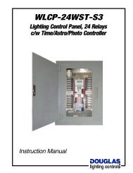
<strong>WLCP</strong>-<strong>36WST</strong>-<strong>S3</strong><br />
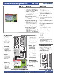
WRS-2224 Relay Scanner<br />
Programming<br />
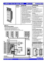
INPUT CONFIGURE MODE<br />
Allows specifying which type(s) of switching hardware can be<br />
connected to each group switch input.<br />
The default switch type for all inputs is the Douglas WR-8501<br />
with Led Indicators. This configuration is compatible with all<br />
models of Douglas relay switches, relay time clocks and photo<br />
cells and no re-configuration is necessary for those devices.<br />
However, if you will be connecting any different switch type(s)<br />
to an input, follow this procedure.<br />
To Use Input Configure Mode:<br />
1. Make sure NORMAL MODE is selected. Its top indicator light should be ON.<br />
2. Use the INPUT SELECT BUTTON to scroll to the group input #1-5 you<br />
wish to configure (when its INPUT LED is ON).<br />
3. Press and hold the OPTIONS MODE select button. The FLICK WARN LED<br />
will begin flashing.<br />
4. One of the OUTPUT LEDs #13-23 will display, showing the current<br />
configuration selected for the input. Refer to the table below for a list of all<br />
available configurations. The factory default is #21, the Douglas WR-<br />
8501 LED indicator rectified AC pulse switch.<br />
5. Depress the OUTPUT SELECT BUTTON(S) (#13-23) to select the desired<br />
configuration(s) for the input.<br />
You have 10 seconds to do this. After 10 seconds, the FLICK WARN LED<br />
stops flashing and the scanner reverts to NORMAL mode.<br />
6. Repeat steps 2-5 to configure other group inputs.<br />
Flick<br />
Warn<br />
LED<br />
Options Mode<br />
Select Button<br />
Output Buttons<br />
#13-#23<br />
Output LEDs<br />
#13-#23<br />
Input<br />
LEDs<br />
Normal Mode<br />
Select Button<br />
Input<br />
Select<br />
Button<br />
Output Button<br />
Pressed<br />
13<br />
14<br />
15<br />
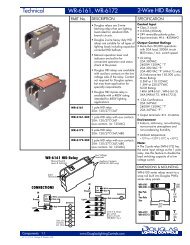
Switch Type Configured for<br />
AC<br />
Momentary<br />
Contact.<br />
Action<br />
(13) - ON when switched<br />
(14) - OFF when switched<br />
(15) - OPEN=OFF / CLOSED=ON<br />
16<br />
17<br />
18<br />
Coil<br />
AC<br />
Maintained<br />
Contact.<br />
(16) - OPEN=ON / CLOSED=OFF<br />
(17) - OPEN=no action / CLOSED=ON<br />
(18) - OPEN=no action / CLOSED=OFF<br />
19<br />
(19) - OPEN=ON / CLOSED=no action<br />
20<br />
21 (Default)<br />
22<br />
23<br />
LEDs<br />
Rectified AC Pulse.<br />
Current for Indicator LEDs.<br />
NOTE: Non-LED switches are also<br />
compatible with this configuration.<br />
Rectified AC Pulse.<br />
No current for Indicator LEDs.<br />
NOTE: LED switches will not function<br />
properly with this configuration.<br />
Table 1. Switch Hardware Type<br />
Components <strong>WLCP</strong>-<strong>36WST</strong>-<strong>S3</strong> 1.1<br />
page 48<br />
(20) - OPEN=OFF / CLOSED=no action<br />
(21) - Positive=OFF / Negative=ON<br />
(22) - Positive=ON / Negative=OFF<br />
(23) - Positive=OFF / Negative=ON<br />
lighting controls