WTI-2332-FT
WTI-2332-FT Telephone Interface - Douglas Lighting Control
WTI-2332-FT Telephone Interface - Douglas Lighting Control
- No tags were found...

Create successful ePaper yourself
Turn your PDF publications into a flip-book with our unique Google optimized e-Paper software.
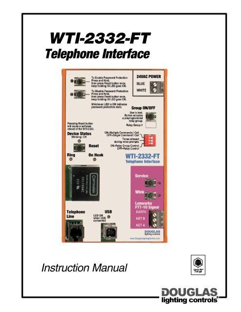
<strong>WTI</strong>-<strong>2332</strong>-<strong>FT</strong><br />
Telephone Interface<br />
Instruction Manual
Contents<br />
Contents<br />
Introduction ........................................................................................................................... 1<br />
Parts .................................................................................................................................... 2<br />
Specifications and Dimensions ............................................................................................... 3<br />
LonWorks Basics ................................................................................................................... 4<br />
<strong>WTI</strong>-<strong>2332</strong>-<strong>FT</strong> Quick-Start Guide ............................................................................................. 5<br />
Telephone Keyboard Commands ............................................................................................ 6<br />
Connecting to an MC-6000 Network ....................................................................................... 7<br />
DIP Switches ......................................................................................................................... 7<br />
Emergency Password ............................................................................................................. 7<br />
LonWorks Data Signal Line Lengths ........................................................................................ 8<br />
LonWorks Network Data for the <strong>WTI</strong>-<strong>2332</strong>-<strong>FT</strong> Device .............................................................. 8<br />
Troubleshooting ..................................................................................................................... 9<br />
Notes .................................................................................................................................. 10<br />
<strong>WTI</strong>-<strong>2332</strong>-<strong>FT</strong>: Directions & Applications<br />
lighting controls
<strong>WTI</strong>-<strong>2332</strong>-<strong>FT</strong> Telephone Interface<br />
Introduction<br />
The <strong>WTI</strong>-<strong>2332</strong>-<strong>FT</strong> allows telephone access to a LonWorks lighting control network or to a Douglas MC-6000 lighting<br />
control network from a standard touch tone phone. The <strong>WTI</strong>-<strong>2332</strong>-<strong>FT</strong> is mounted in the relay panel and is connected to<br />
the network data signal. The telephone connects to the modem jack on the <strong>WTI</strong>-<strong>2332</strong>-<strong>FT</strong>. The user then dials into the<br />
<strong>WTI</strong>-<strong>2332</strong>-<strong>FT</strong> line and, using simple key commands, can monitor the status of any of the relay groups, or individual<br />
relays, within the network or turn them ON or OFF from the telephone.<br />
Enable Password<br />
Button & LED<br />
Press and hold, then press Reset<br />
button to enable password protection.<br />
Keep holding unil LED is ON, indicating<br />
password protection is active.<br />
Disable Password<br />
Button & LED<br />
Press and hold, then press Reset<br />
button to disable password protection.<br />
Keep holding until LED is ON, indicating<br />
password protection is inactive.<br />
Power Indicator LED<br />
Flashes when unit is receiving power.<br />
Reset Button<br />
Press and hold at startup to<br />
restore defaults.<br />
Power Indicator LED<br />
Flashes when a call is being sent.<br />
Telephone Online<br />
Indicator LED<br />
ON when modem is active.<br />
RJ11 Jack<br />
Connect the telephone line here.<br />
USB Port & LED<br />
Connect the USB from a pc for using the<br />
pc hyperterminal to configure the unit.<br />
LED flashes when pc is connected and a<br />
signal is being transmitted.<br />
24V Power Terminals<br />
Connect to 24V transformer in panel.<br />
Group Test Button<br />
Press to toggle preselected (during<br />
system configuration) LonWorks group<br />
ON and OFF.<br />
DIP Switches<br />
Factory setting is all 3 switches in<br />
ON (right) position:<br />
OFF<br />
ON<br />
1<br />
2<br />
3<br />
#1 ON (single command mode: one<br />
command per session)<br />
#1 OFF (multiple command mode: more<br />
than one command per session)<br />
#2 ON (can enter command before<br />
voice prompt ends)<br />
#2 OFF (cannot enter command until<br />
voice prompt ends)<br />
#3 ON (default menu is relay groups<br />
activated).<br />
#3 OFF (default menu is individual relays<br />
activated).<br />
Service Button & LED<br />
Press the button to identify unit to<br />
network for diagnosis.<br />
Flashing LED indicates defective unit.<br />
Wink Button & LED<br />
LED flashes when a network Wink<br />
command is received.<br />
Press the button to clear Wink command.<br />
Data Signal Connections<br />
Connect LonWorks network data signal<br />
here.<br />
For LonWorks networks: data signal is<br />
<strong>FT</strong>T10 (78kbs), wiring is 16AWG<br />
twisted pair, non-polarized unshielded<br />
striated or solid.<br />
For MC-6000 networks: connect to<br />
LonWorks signal input terminals on MC-<br />
6210N-GTW card.<br />
<strong>WTI</strong>-<strong>2332</strong>-<strong>FT</strong>: Directions & Applications page 1 lighting controls
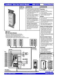
Parts<br />
<strong>WTI</strong>-<strong>2332</strong>-<strong>FT</strong> Telephone Interface<br />
Password Enable Button & LED<br />
To activate password protection,<br />
press and hold button, then<br />
press Reset button. Keep<br />
holding until LED comes ON.<br />
LED is ON when password<br />
protection is activated.<br />
Password Disable Button & LED<br />
to disable password protection<br />
press and hold button, then press<br />
Reset button. Keep holding till LED<br />
comes ON.<br />
LED is ON when password<br />
protection is disabled.<br />
Power Indicator LED<br />
Flashes when unit is receiving power.<br />
Reset Button<br />
Press and hold at startup<br />
to restore defaults.<br />
Ring LED<br />
Flashes when a call is<br />
being sent.<br />
Telephone Online<br />
Indicator LED<br />
On when the modem is active.<br />
RJ11 Jack<br />
Connect the telephone line here.<br />
Pressing Reset Button<br />
will cause a software<br />
reboot of the <strong>WTI</strong>-<strong>2332</strong>.<br />
Device Status<br />
Ring<br />
Blinking= OK<br />
Telephone<br />
Line<br />
To Enable Password Protection<br />
Press and Hold,<br />
the press Reset button once,<br />
keep holding till LED goes ON.<br />
To Disable Password Protection<br />
Press and Hold,<br />
the press Reset button once,<br />
keep holding till LED goes ON.<br />
Whichever LED is ON indicates<br />
password protection state.<br />
Reset<br />
On Hook<br />
LED ON<br />
when USB<br />
connected<br />
24VAC POWER<br />
BLUE<br />
WHITE<br />
Group ON/OFF<br />
Use to test.<br />
Button actuates<br />
a preprogrammed<br />
relay group.<br />
Relay Group #<br />
ON=Multiple Commands / Call<br />
OFF=Single Command / Call<br />
Tones allowed<br />
during voice prompts<br />
ON=Relay Group Control<br />
OFF=Relay Control<br />
USB<br />
<strong>WTI</strong>-<strong>2332</strong>-<strong>FT</strong><br />
Telephone Interface<br />
Service<br />
Wink<br />
Lonworks<br />
<strong>FT</strong>T-10 Signal<br />
EARTH<br />
NET B<br />
NET A<br />
www.DouglasLightingControl.com<br />
Power Terminals<br />
Connected to 25VAC/120VAC transformer.<br />
Test Button<br />
Press button to toggle pre-selected<br />
(during system configuration) LonWorks<br />
group ON and OFF.<br />
OFF<br />
ON<br />
1<br />
2<br />
3<br />
DIP Switches<br />
Factory setting is all switches in ON (right)<br />
position.<br />
1 ON = single command mode.<br />
2 ON = command can be started before<br />
voice prompt ends.<br />
3 ON = default menu is relay groups<br />
activated.<br />
1 OFF = multiple command mode.<br />
2 OFF = command cannot be started<br />
until voice prompt ends.<br />
3 OFF = default menu is individual relays<br />
activated.<br />
Service LED and Pin<br />
LED: flashes when unit is malfunctioning.<br />
Pin: press to identify unit to network for<br />
diagnosis.<br />
Wink LED and Pin<br />
LED: flashes when network Wink<br />
command received.<br />
Pin: press to clear Wink command.<br />
USB Port and LED<br />
Connect the USB from a pc here<br />
for using the pc's hyperterminal<br />
to configure the unit.<br />
LED flashes when a pc is<br />
connected and a signal is being<br />
transmitted.<br />
Data Signal Terminals<br />
Connect network data signal here.<br />
For LonWorks networks: data signal is<br />
<strong>FT</strong>T10 (78kbs), wiring is 16AWG<br />
twisted pair, non-polarized unshielded<br />
striated or solid.<br />
For MC-6000 networks: connect to the<br />
LonWorks signal input terminals on the<br />
MC-6210N-GTW card.<br />
<strong>WTI</strong>-<strong>2332</strong>-<strong>FT</strong>: Directions & Applications page 2 lighting controls
Specifications & Dimensions<br />
Specifications<br />
Connections<br />
Power:<br />
24VAC / 100mA<br />
Network Technology Specification<br />
LonWorks® technology.<br />
LonWorks Data Signal<br />
<strong>FT</strong>T-10 (78 kbs) standard LonTalk data signal.<br />
Wiring is 16AWG twisted pair, unshielded cable, stranded<br />
or solid conductor.<br />
Connections are polarity insensitive.<br />
Data signal wiring to the panel must be included in the<br />
overall network data signal line length calculations.<br />
For a Douglas MC-6000 system, the LonWorks data signal<br />
connects from the <strong>WTI</strong>-<strong>2332</strong>-<strong>FT</strong> to the LonWorks signal<br />
terminals of a MC-6210N-GTW Card. The MC-6210N-<br />
GTW Card must have its own address with respect to the<br />
MC-6000 system.<br />
Telephone:<br />
Dedicated telephone line from a touch-tone phone to<br />
the RJ11 jack.<br />
Environment<br />
Indoors, stationary, non-vibrating, non-corrosive<br />
atmosphere and non-condensing humidity.<br />
Ambient operating temperature:<br />
0 O F to +120 0 F (-15 O to +50 O C).<br />
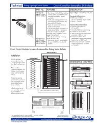
DIMENSIONS & MOUNTING<br />
<br />
Telephone Interface mounts to 35mm<br />
DIN rail installed in relay panels.<br />
Unit shipped with DIN mounting rail.<br />
Operation<br />
The <strong>WTI</strong>-<strong>2332</strong>-<strong>FT</strong> is accessed by dialing the telephone<br />
number provided by the System Administrator.<br />
Dialing must be paced and deliberate.<br />
6.5"<br />
(165)<br />
6.5"<br />
(165)<br />
<strong>WTI</strong>-<strong>2332</strong>-<strong>FT</strong><br />
Telephone Interface<br />
Upon connection, a password can be required, and is<br />
entered with the telephone keypad.<br />
Each telephone command, entered with the telephone<br />
keypad, consists of the function code (ON, OFF or status),<br />
group number (or individual relay number) and the initiation<br />
code ('#").<br />
Voice prompts are provided by the system.<br />
4.0"<br />
(103)<br />
Plan View<br />
1.75"<br />
(45)<br />
Side View<br />
<strong>WTI</strong>-<strong>2332</strong>-<strong>FT</strong>: Directions & Applications page 3 lighting controls
LonWorks Basics<br />
LONWORKS<br />
The <strong>WTI</strong>-<strong>2332</strong>-<strong>FT</strong> has been designed to function as part of a<br />
LonWorks network.<br />
LONWORKS refers to a technology platform for components used in<br />
control networks. A component, to be certified as LonMark (meeting<br />
the LonWorks standard), must meet the functional standards specified<br />
for its device (also called node) type. The advantage to this is<br />
interoperability. That is, in a LonWorks network, a device/node from<br />
any manufacturer can be used for performing the function specified<br />
for that particular device/node type.<br />
<strong>WTI</strong>-<strong>2332</strong>-<strong>FT</strong><br />
6.5"<br />
(165) <strong>WTI</strong>-<strong>2332</strong>-<strong>FT</strong><br />
Telephone Interface<br />
Node #4<br />
LonWorks nodes generally contain a chip called a neuron. The neuron<br />
has imbedded software that directs the node in performing its<br />
networking functions. The neuron 'listens' for messages from other<br />
LonWorks devices/nodes on the network. When it 'hears' a type of<br />
message that it is programmed to respond to, it sends a specific type<br />
of message in response.<br />
Relay #1<br />
Relays<br />
#2 & #3<br />
Relay #4<br />
CONFIGURATION<br />
A Douglas W-2000 LonWorks lighting control network consists of<br />
devices that are configured to receive/send signals to/from other<br />
devices in the network. Each device/node must have an ID and must<br />
recognize the IDs of all the other devices on the network so that it can<br />
send/receive messages to/from the appropriate devices. Each device<br />
is configured to respond in a specific manner to any message it is<br />
able to receive.<br />
In a Douglas W-2000 LonWorks network, configuration can be done<br />
by an external BAS (building automation system) connected to the<br />
network, or by a pc connected by ethernet to a Douglas WNP-2150<br />
Network Manager that is part of the network. Or, it can be done<br />
automatically (self-configured) by a Douglas WNX-2624 device within<br />
the network that is designated as the Network Manager.<br />
The BAS or Network Manager will assign ID numbers to the devices in<br />
the network as well as to each of their switch inputs and willl bind, or<br />
assign, the relay output groups to the appropriate switch inputs.<br />
The BAS or Network Manager will know which node (by its Node ID<br />
number) has which switch inputs (by their input ID numbers) and<br />
which output relays (by the binding) each of those switch inputs<br />
controls. When the system is operating and a switch input is<br />
triggered, the BAS or Network Manager will recognize where it is, will<br />
recognize which output relays it is to trigger, and will generate a signal<br />
to trigger those output relays as a group.<br />
THE <strong>WTI</strong>-<strong>2332</strong>-<strong>FT</strong> TELEPHONE INTERFACE<br />
The <strong>WTI</strong>-<strong>2332</strong>-<strong>FT</strong> Telephone Interface is LonMark-compliant and<br />
can function as device within a LonWorks network. Once properly<br />
connected and configured, it will have a unique node ID.<br />
The function of the the <strong>WTI</strong>-<strong>2332</strong>-<strong>FT</strong> is to allow the operator, who<br />
connects to the <strong>WTI</strong>-<strong>2332</strong>-<strong>FT</strong> with a touch-tone phone, to monitor<br />
the status of each of the output relay groups bound to the switch<br />
inputs throughout the LonWorks network. As well, the<br />
<strong>WTI</strong>-<strong>2332</strong>-<strong>FT</strong> will allow the operator to turn any output relay<br />
group ON or OFF.<br />
Node #1<br />
Data Signal<br />
Node #2<br />
Node #3<br />
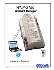
Network Example with <strong>WTI</strong>-<strong>2332</strong>-<strong>FT</strong> Telephone Interface<br />
AN EXAMPLE<br />
An example of a Douglas W-2000 LonWorks Network with a <strong>WTI</strong>-<br />
<strong>2332</strong>-<strong>FT</strong> Telephone Interface is shown above. The network<br />
consists of three panels, each that contain the WRS-2224<br />
Programmable Relay Scanner/WNX-2624 Network Node, and a<br />
fourth panel that contains the <strong>WTI</strong>-<strong>2332</strong>-<strong>FT</strong> Telephone Interface.<br />
They are networked with a data signal that is connected to each<br />
WNX-2624 and to the input and output of the <strong>WTI</strong>-<strong>2332</strong>-<strong>FT</strong>.<br />
Node ID #'s are assigned to each of the Network Nodes and the<br />
Telephone Interface. Output group ID #'s are assigned to all the<br />
output relay groups. The output relays assigned to each output<br />
group I are bound to its group ID #.<br />
In the example above, an output group consists of four relays.<br />
The first relay (relay #1) is connected to an output on the scanner<br />
with Node #1. The second and third relays (relays #2 and #3)<br />
are connected to outputs on the scanner with Node #2. The<br />
fourth relay (relay #4) is connected to an output on the scanner<br />
with Node #3.<br />
The configuration recognizes this and assigns an Input ID number (in<br />
this example, Output Group # 18) to the switch and binds all four<br />
relays to that group number.<br />
When the operator signals the <strong>WTI</strong>-<strong>2332</strong>-<strong>FT</strong> Telephone Interface<br />
(Node #4) to turn Group #18 ON or OFF, the <strong>WTI</strong>-<strong>2332</strong>-<strong>FT</strong><br />
transmits that signal to the network and the network will turn the<br />
relays that are bound to the Group (relays #1, #2 #3 and #4)<br />
ON or OFF accordingly.<br />
<strong>WTI</strong>-<strong>2332</strong>-<strong>FT</strong>: Directions & Applications page 4 lighting controls
To get the <strong>WTI</strong>-<strong>2332</strong>-<strong>FT</strong> up and running:<br />
1. Install the <strong>WTI</strong>-<strong>2332</strong>-<strong>FT</strong> in the relay panel.<br />
Mount in the panel per the diagram on page 3.<br />
2. Connect the network data signal to the <strong>WTI</strong>-<strong>2332</strong>-<strong>FT</strong>.<br />
For a Douglas W-2000 or an external LonWorks network, connect<br />
the data signal to the NET A and NET B terminals. Connection are<br />
polarity insensitive. Connections are shown on the diagram on page<br />
2. For a MC-6000 network, connect the data signal from NET A<br />
and NET B terminals to the LonWorks signal terminals on the MC-<br />
6210N-GTW Card within the MC-6000 network. The MC-6210N-<br />
GTW Card must have an address with respect to the MC-6000. The<br />
MC-6000 network connections are shown on the diagram on page 7.<br />
3. Connect the telephone line to the RJ11 jack.<br />
Connect the dedicated telephone line to the RJ11 jack, as shown<br />
on the diagram on page 2. It is recommended that you find out and<br />
make note of the dial-in telephone number at this time. Record it in<br />
the space provided on page 10 of this manual.<br />
4. Power up the panel.<br />
The Power Indicator LED will flash when the unit is receiving power.<br />
5. Make sure the DIP switch settings are correct.<br />
Factory default is all three switches in the ON position (#1 ON -<br />
single command mode, #2 ON- can enter command during voice<br />
prompt, #3 ON- Relay Groups Menu.) If these settings are not what<br />
you wish to use, change them. Refer to the table on page 7.<br />
6. Dial the telephone number on the telephone.<br />
The telephone connected to the modem must be a touch-tone<br />
type. If you are not certain of the correct telephone number, check<br />
with the Network System Administrator.<br />
If you receive a busy signal, another user is accessing the interface<br />
and you will not be able to make a connection. Try again later.<br />
7. Once the telephone connection is made, provide the<br />
password using the telephone keypad.<br />
When the connection is made after dial-up, a voice prompt states<br />
"Welcome to the lighting control system. Enter your password,<br />
followed by the pound key."<br />
Enter the password using the telephone keypad. For instance, if the<br />
password is 1,2,3,4 (factory default password), Press 1, 2, 3, 4, #.<br />
Hit the keys slowly and deliberately and you should not start until<br />
the voice prompt is finished. This procedure is the same when<br />
entering any command or response on the telephone keypad.<br />
When the password is accepted, a voice prompt states "Password<br />
accepted."<br />
If the <strong>WTI</strong>-<strong>2332</strong>-<strong>FT</strong> is set for no password, you will not be<br />
requested to enter a password. Instead, you will immediately be<br />
sent to the Select Group or Select Individual Relay Menu.<br />
8. Activate, or query the status of, a relay group or an<br />
indidual relay using the telephone keypad.<br />
If DIP Switch #3 has been set to ON, the Relay Groups Menu will<br />
now appear. If DIP Switch #3 had been set to OFF, the Individual<br />
Relay Menu will now appear.<br />
GROUP MENU (you activate output relay groups).<br />
After the system accepts your password a voice prompt will say<br />
"Welcome to the Group Menu. Enter '3' for OFF or '6' for ON,<br />
followed by the relay number and the pound key."<br />
<strong>WTI</strong>-<strong>2332</strong>-<strong>FT</strong> Quick-Start Guide<br />
8. (continued)<br />
Enter the group activation/query command, using the keypad. The<br />
sequence is:<br />
- '3' (to turn OFF) or '6' (to turn ON) or '7' (to hear present status)<br />
- group number (1 to 3 digits, 1 to 255)<br />
- '#'.<br />
For instance, the key sequence to turn OFF relay group #25 would<br />
be '3', '2', '5', '#'.<br />
When the command is received and acted upon, the voice prompt<br />
will say "Group is ON" or "Group is OFF" as appropriate.<br />
INDIVIDUAL RELAY MENU (you activate individual relays)<br />
After the system accepts your password a voice prompt will say<br />
"Welcome to the Individual Relay Menu. Enter '3' for OFF or '6' for ON,<br />
followed by the panel number, relay number and the pound key."<br />
Enter the relay activation/query command, using the keypad. The<br />
sequence is:<br />
- '2' (to mask OFF) or '3' (to turn OFF) or '6' (to turn ON) or '7' (to<br />
mask ON) or '8' (to turn ON with a Timeout)<br />
- panel number (1 to 3 digits, 5 to 250)<br />
-individual relay number (2 digits, 01 to 64)<br />
- '#'.<br />
For instance, the key sequence to turn ON relay #05 in panel #5<br />
would be '6', '5', '0', '5', '#'. Or, the key sequence to turn OFF<br />
relay #10 in panel #123 would be '3', '1', '2', '3', '1', '0','#'.<br />
9. Repeat step 8 to activate or query status of other group(s)<br />
or individual relay(s).<br />
Use the same key sequence. For Relay Groups: 3 ( turn OFF) or 6 (turn<br />
ON) or 7 (query), group number, #. For Individual Relays: 2 (mask OFF)<br />
or 3 (turn OFF) or 6 (turn ON) or 7 (mask ON) or 8 (turn ON with<br />
timeout), panel number, individual relay number, #.<br />
10. To toggle to the other Menu, press the '4' key.<br />
If you are in the Group Menu, where you activate relay groups, and<br />
want to go to the Individual Relay Menu, where you activate<br />
individual relays -or vice versa- press the '4' key, then press '#'..<br />
Follow the voice prompts and use keyboard commands, exactly as in<br />
steps 8 & 9, to activate groups or individual relays using the other<br />
Menu.<br />
At any time, you can toggle from one Menu to another by pressing<br />
'4', then '#' .<br />
12. To initiate another type of command, use the<br />
appropriate key sequence, as listed on page 6.<br />
Other types of commands include change password and override<br />
flick warn. Refer to the table on page 6 for keyboard commands.<br />
13. To terminate the telephone connection, simply hang up.<br />
When you hang up, the controller with automatically terminate the<br />
connection and retain all saved information from the commands<br />
that were properly entered.<br />
The system will also disconnect the telephone if there are several<br />
seconds of inactivity. The system will prompt the user before<br />
disconnecting.<br />
<strong>WTI</strong>-<strong>2332</strong>-<strong>FT</strong>: Directions & Applications page 5 lighting controls
Telephone Keypad Commands<br />
ENTERING COMMANDS USING THE TELEPHONE KEYPAD<br />
You enter commands by pressing on the number keys on the telephone<br />
keypad.<br />
You should wait until the voice prompt is completed before starting, then<br />
press the keys slowly and deliberately. When your command is accepted,<br />
you will hear a voice prompt confirmation or response.<br />
Below is a table that lists the telephone commands that you can use with<br />
the <strong>WTI</strong>-<strong>2332</strong>-<strong>FT</strong>.<br />
1 2 3<br />
4 5 6<br />
7 8 9<br />
* 0 #<br />
Command<br />
Enter Password<br />
Enter New Password<br />
(note: default is no password)<br />
Set for No Password<br />
Activate or<br />
Query Status of<br />
Output Relay Group<br />
Activate an<br />
Individual Relay<br />
(generally used with<br />
MC-6000 Network)<br />
Toggle between<br />
Group Menu and<br />
Individual Relay Menu<br />
Disconnect<br />
Procedure<br />
1. (voice prompt says "enter your password...")<br />
2. Enter digits of password, then '#'. For example, if password is 1234, enter '1', '2', '3', '4', '#'.<br />
3. (voice prompt says "password accepted")<br />
1. Press '9', then '#'.<br />
2. (voice prompt says "enter your password...")<br />
3. Enter digits (4 to 6) of password, then '#'. For example, if password is 1234, enter '1', '2', '3', '4', '#'.<br />
4. (voice prompt says "re-enter password...")<br />
5. Enter digits of password, then '#'.<br />
6. (voice prompt says "password accepted")<br />
1. Press '9', then '#'.<br />
2. (voice prompt says "enter your password...")<br />
3. Enter '5', '5', '#'. (OR)<br />
1. Press and hold Disable Password button.<br />
2. While continuing to hold Disable Password<br />
button, press Reset button.<br />
3. LED by Disable Password button will ON,<br />
indicating default settings are restored,<br />
including no password.<br />
1. go to Group Menu (default when DIP Switch #3 is ON, or toggle from Individual Relay Menu).<br />
2. (voice prompt says "welcome to the Group Menu...")<br />
3. Enter '3' (if group to be turned OFF) or '6' (if group to be turned ON) or '7' (to query group's status).<br />
4. Enter digits of group number, which can be 1-255 (example: for group #23, enter ''2', '3' ).<br />
5. Enter '#'.<br />
6. (voice prompt says "group is ON" or "group is OFF", as appropriate)<br />
7. Repeat steps 2-6 to activate other groups.<br />
1. go to Individual Relay Menu (default when DIP Switch #3 is OFF, or toggle from Group Menu).<br />
2. (voice prompt says "welcome to the Individual Relay Menu...")<br />
3. Enter the action: '2' (to unmask relay) or '3' (to turn OFF relay) or '6' (if relay to be turned ON) or '7' (to<br />
mask relay) or '8' (to turn relay ON with a Timeout).<br />
4. Enter 1-3 digits of panel number, which can be 5 to 250 (example: for panel #125, enter '1', '2', '5' ).<br />
5. Enter 2 digits of relay number, which can be 01 to 64 (examples: for relay #4, enter '0', '4'; for<br />
relay #61, enter '6', '1'.<br />
6. Enter '#'.<br />
8. Repeat steps 2-7 to activate other individual relays.<br />
1. press '4', then '#'.<br />
2. (voice prompt says "welcome to the (other) Menu.")<br />
1. hang up.<br />
<strong>WTI</strong>-<strong>2332</strong>-<strong>FT</strong>: Directions & Applications page 6 lighting controls
www.DouglasLightingControl.com<br />
1<br />
2<br />
4<br />
8<br />
16<br />
32<br />
64<br />
lighting controls<br />
Connecting to MC-6000 Network / DIP Switches / Emergency Password<br />
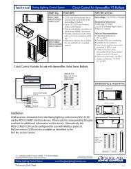
CONNECTING TO AN MC-6000 NETWORK<br />
Connect the LonWorks data signal of the <strong>WTI</strong>-<strong>2332</strong>-<strong>FT</strong> to the LonWorks input<br />
terminals of an MC-6210N-GTW Card, which connects to the MC-6000 data<br />
signal. The MC-6210N-GTW Card must have its own address with respect<br />
to the MC-6000 System.<br />
To Enable Password Protection<br />
Press and Hold,<br />
the press Reset button once,<br />
keep holding till LED goes ON.<br />
To Disable Password Protection<br />
Press and Hold,<br />
the press Reset button once,<br />
keep holding till LED goes ON.<br />
24VAC POWER<br />
BLUE<br />
WHITE<br />
Panel Bus<br />
Activity<br />
Panel<br />
Bus<br />
MC-6210N-GTW<br />
Panel Control Card<br />
V#<br />
<strong>WTI</strong>-<strong>2332</strong>-<strong>FT</strong><br />
Whichever LED is ON indicates<br />
password protection state. Group ON/OFF<br />
Use to test.<br />
Button actuates<br />
a preprogrammed<br />
relay group.<br />
Pressing Reset Button<br />
will cause a software<br />
Relay Group #<br />
reboot of the <strong>WTI</strong>-<strong>2332</strong>.<br />
ON=Multiple Commands / Call<br />
Device Status<br />
OFF=Single Command / Call<br />
Blinking= OK<br />
Tones allowed<br />
during voice prompts<br />
Reset ON=Relay Group Control<br />
OFF=Relay Control<br />
Ring On Hook<br />
<strong>WTI</strong>-<strong>2332</strong>-<strong>FT</strong><br />
Telephone Interface<br />
128<br />
All<br />
ON<br />
MC-6210N-GTW<br />
OFF ON<br />
All<br />
OFF<br />
Wink<br />
Card Power White<br />
(24 vac) Blue<br />
Telephone<br />
Line<br />
USB<br />
LED ON<br />
when USB<br />
connected<br />
Lonworks<br />
<strong>FT</strong>T-10 Signal<br />
EARTH<br />
NET B<br />
NET A<br />
<strong>FT</strong>T-10<br />
LonWorks<br />
Data Signal<br />
EARTH<br />
NET B<br />
NET A<br />
Data Signal<br />
A B<br />
Test<br />
Signal<br />
Handheld<br />
Keypad KB-3031<br />
Data<br />
Signal<br />
Activity<br />
Service<br />
MC-6000 System<br />
RS-485 Data Signal<br />
DIP SWITCHES<br />
There are three DIP switches located at the center right of the <strong>WTI</strong>-<strong>2332</strong>-<strong>FT</strong> unit, as shown.<br />
Each switch can be set to the ON or OFF position, with factory default being all 3 switches ON.<br />
Switch settings can be changed at any time, although the unit may have to be restarted before changes take effect.<br />
Switch<br />
1<br />
2<br />
3<br />
Settings<br />
ON: Single command mode: one command when telephone<br />
connected to <strong>WTI</strong>-<strong>2332</strong>-<strong>FT</strong>, then connection terminated.<br />
OFF: Multiple command mode: unlimited number of<br />
commands when telephone connected to <strong>WTI</strong>-<strong>2332</strong>-<strong>FT</strong>.<br />
ON: A command can started on the keypad before the voice<br />
prompt ends.<br />
OFF: A command cannot be started on the keypad until after<br />
the voice prompt ends.<br />
ON: Group Menu is default Menu. This is the Menu you<br />
generally would use with a LonWorks network.<br />
OFF: Individual Relay Menu is default Menu. This is the Menu<br />
you generally would use with a MC-6000 network.<br />
NOTE: Either menu can be used with both LonWorks<br />
and MC-6000 networks.<br />
To Enable Password Protection 24VAC POWER<br />
Press and Hold,<br />
the press Reset button once, BLUE<br />
keep holding till LED goes ON.<br />
To Disable Password Protection WHITE<br />
Press and Hold,<br />
the press Reset button once,<br />
keep holding till LED goes ON.<br />
Whichever LED is ON indicates<br />
password protection state. Group ON/OFF<br />
Use to test.<br />
Button actuates<br />
a preprogrammed<br />
relay group.<br />
Pressing Reset Button<br />
will cause a software<br />
Relay Group #<br />
reboot of the <strong>WTI</strong>-<strong>2332</strong>.<br />
ON=Multiple Commands / Call<br />
Device Status<br />
OFF=Single Command / Call<br />
Blinking= OK<br />
Tones allowed<br />
during voice prompts<br />
Reset ON=Relay Group Control<br />
OFF=Relay Control<br />
Ring On Hook<br />
<strong>WTI</strong>-<strong>2332</strong>-<strong>FT</strong><br />
Telephone Interface<br />
Telephone<br />
Line<br />
USB<br />
LED ON<br />
when USB<br />
connected<br />
Service<br />
Wink<br />
Lonworks<br />
<strong>FT</strong>T-10 Signal<br />
EARTH<br />
NET B<br />
NET A<br />
www.DouglasLightingControl.com<br />
DIP Switches<br />
OFF ON<br />
1<br />
2<br />
3<br />
EMERGENCY PASSWORD<br />
if the system will not accept your password when you dial in to the<br />
<strong>WTI</strong>-<strong>2332</strong>-<strong>FT</strong> -for instance if the password was changed without your<br />
knowledge- and you are unable to set the unit to no password, you<br />
can use the emergency password to connect to the <strong>WTI</strong>-<strong>2332</strong>-<strong>FT</strong>.<br />
Emergency Password: 00735<br />
After you enter the <strong>WTI</strong>-<strong>2332</strong>-<strong>FT</strong> with the emergency pasword, it is<br />
recommended that you create a new, unique password for the unit.<br />
Wti-<strong>2332</strong>-<strong>FT</strong>: Directions & Applications page 7 lighting controls
LonWorks Data Signal Line Lengths / LonWorks Data<br />
LONWORKS DATA SIGNAL LINE LENGTHS<br />
The <strong>WTI</strong>-<strong>2332</strong>-<strong>FT</strong> connects to the network via a <strong>FT</strong>T-10 Data Signal.<br />
The topology, or the layout of the network, can be either of two basic types:<br />
• Bus Topology Network, where all devices are connected to one central<br />
data line called the bus. Essentially, panels in a bus topology network<br />
are connected in series.<br />
• Free Topology Network, where devices are connected to data line<br />
segments which can be joined in any manner. Essentially, devices in a<br />
free topology network are connected at random.<br />
The lengths of the data signal line segment to the <strong>WTI</strong>-<strong>2332</strong>-<strong>FT</strong> must be<br />
included in the calculation for the maximum allowable line lengths for the<br />
network. Refer to the following table:<br />
Node Node Node Node Node Node<br />
Node<br />
Node<br />
Node Node<br />
Bus Topology<br />
Node Node Node<br />
Node Node<br />
Free Topology<br />
<strong>FT</strong>T-10<br />
Data Signal Type<br />
#16 AWG, twisted pair,<br />
no shield, Belden 85102<br />
#16 AWG, twisted pair,<br />
no shield, Belden 8471<br />
Maximum length<br />
(total network)<br />
Bus Topology<br />
8500 ft<br />
(2700m)<br />
8500 ft<br />
(2700m)<br />
Free Topology<br />
1600 ft<br />
(500m)<br />
1250 ft<br />
(400m)<br />
Maximum length<br />
(device-to-device)<br />
Bus Topology<br />
N/A<br />
N/A<br />
Free Topology<br />
1600 ft<br />
(500m)<br />
1250 ft<br />
(400m)<br />
Maximum length<br />
(stub length)<br />
Bus Topology Free Topology<br />
10 ft<br />
(3m)<br />
10 ft<br />
(3m)<br />
N/A<br />
N/A<br />
Maximum number<br />
of devices<br />
Bus Topology<br />
Free Topology<br />
64 64<br />
64 64<br />
Level IV, 22AWG<br />
Category 5 Cable<br />
Standard: TIA 568A<br />
4400 ft<br />
(1400m)<br />
2800 ft<br />
(900m)<br />
1250 ft<br />
(400m)<br />
1400 ft<br />
(450m)<br />
N/A<br />
N/A<br />
1250 ft<br />
(400m)<br />
1400 ft<br />
(450m)<br />
10 ft<br />
(3m)<br />
10 ft<br />
(3m)<br />
N/A<br />
N/A<br />
64<br />
64<br />
64<br />
64<br />
LONWORKS NETWORK DATA FOR THE <strong>WTI</strong>-<strong>2332</strong>-<strong>FT</strong><br />
This information is for System Integrators who are integrating the <strong>WTI</strong>-<strong>2332</strong>-<strong>FT</strong><br />
into a LonWorks system.<br />
Functional Profiles<br />
■<br />
Node Object Type: 0<br />
<br />
Scene Panel Type: 3250<br />
Network Variables<br />
<br />
nvoScene for group activation<br />
(via external LPC)<br />
■<br />
nviSceneFb for group status feedback<br />
LonMark® Profiles<br />
Scene Panel<br />
Type 3250<br />
nviSceneFb Mandatory<br />
1 SNVT_scene Network 2<br />
Variables<br />
nciConfigSource<br />
nciLocation<br />
nciSceneTest<br />
nciTimeoutMsg<br />
nciDelay<br />
nviPassword<br />
nvoActuator<br />
UCPTPasswordRetry<br />
UCPTPassword<br />
nvoScene<br />
SNVT_scene<br />
<strong>WTI</strong>-<strong>2332</strong>-<strong>FT</strong>: Directions & Applications page 8 lighting controls
Troubleshooting<br />
General Guidelines:<br />
Make sure that 24V power exists in the panels (always measure between 22VAC and 30VAC);<br />
Make sure that the data signal is securely connected to the proper terminal(s) of the <strong>WTI</strong>-<strong>2332</strong>-<strong>FT</strong>;<br />
Make sure the modem is securely connected to the <strong>WTI</strong>-<strong>2332</strong>-<strong>FT</strong>;<br />
Make sure all relay groups are programmed correctly;<br />
Make sure to use the Group Menu for a LonWorks network and the Individual Relay Menu for a MC-6000 network.<br />
Problem Encountered Possible Cause(s) Corrective Action<br />
No Power to Unit<br />
(Power Indicator LED off)<br />
Improper input voltage (must be<br />
between 22VAC and 30VAC).<br />
External AC current leaking into circuit.<br />
- check connections.<br />
- check power source.<br />
- check wiring for shorts or grounding.<br />
Password not Accepted Password previously changed. - set to default no password, then set new password.<br />
- use emergency password, then set new password.<br />
Output Relay Groups, or<br />
Relays, not responding<br />
properly<br />
Service LED flashing<br />
once every second<br />
Improper input voltage (must be<br />
between 22VAC and 30VAC).<br />
DIP switch not set correctly.<br />
Wrong Menu (relay groups or<br />
individual relays) used.<br />
Wrong group or relay number used.<br />
Bad telephone connection.<br />
<strong>WTI</strong>-<strong>2332</strong>-<strong>FT</strong> is not configured into network.<br />
<strong>WTI</strong>-<strong>2332</strong>-<strong>FT</strong> unit is defective.<br />
- check connections.<br />
- check power source.<br />
- check DIP switch settings: #3 should be set to<br />
ON for relay groups or OFF for individual relays.<br />
- change default Menu.<br />
- check schedules for correct group or relay numbers.<br />
- check all connections to telephone and modem.<br />
- check voltage to modem.<br />
- restart panel, and Network Manager device<br />
will reconfigure network to include <strong>WTI</strong>-<strong>2332</strong>-<strong>FT</strong>.<br />
- replace <strong>WTI</strong>-<strong>2332</strong>-<strong>FT</strong>.<br />
<strong>WTI</strong>-<strong>2332</strong>-<strong>FT</strong> Troubleshooting Guide<br />
<strong>WTI</strong>-<strong>2332</strong>-<strong>FT</strong>: Directions & Applications page 9 lighting controls
Notes<br />
Telephone Number for dialing into <strong>WTI</strong>-<strong>2332</strong>-<strong>FT</strong><br />
<strong>WTI</strong>-<strong>2332</strong>-<strong>FT</strong>: Directions & Applications page 10 lighting controls
Notes<br />
<strong>WTI</strong>-<strong>2332</strong>-<strong>FT</strong>: Directions & Applications page 11 lighting controls
www.DouglasLightingControls.com<br />
4455 Juneau Street • Burnaby, B.C. • CANADA<br />
phone: (604) 873-2797 • fax: (604) 873-6939<br />
WARRANTY<br />
DOUGLAS products are warranted for one year from the<br />
date of purchase by the consumer against defects due<br />
to materials and the company's worksmanship only. The<br />
sole obligation hereunder shall be to repair, or at the<br />
company's option to replace, products as aforesaid,<br />
provided same are returned, upon authorization,<br />
'Transportation Prepaid' to the company's Burnaby,<br />
CANADA office within the said period. Defects or failures<br />
due to improper or careless installation, storage or<br />
handling, or usage other than rated conditions, are<br />
specifically excluded from this warranty. No liability is<br />
accepted for return transportation charges following<br />
repair or replacement as aforesaid or for reinstallation<br />
costs. No other liability of any nature or kind, whether<br />
arising out of or from the use of the product, whether or<br />
not defective, is assumed.<br />
DOUGLAS lighting controls reserves the right to cancel or<br />
change items shown in this publication without notice.