(oxygen)
installation instructions and owner's manual - White Mountain Hearth
installation instructions and owner's manual - White Mountain Hearth

You also want an ePaper? Increase the reach of your titles
YUMPU automatically turns print PDFs into web optimized ePapers that Google loves.
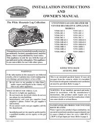
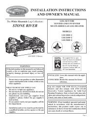
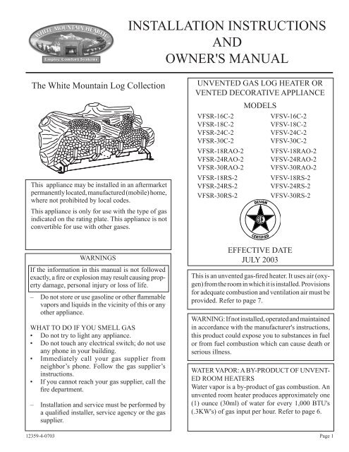
INSTALLATION INSTRUCTIONS<br />
AND<br />
OWNER'S MANUAL<br />
The White Mountain Log Collection<br />
This appliance may be installed in an aftermarket<br />
permanently located, manufactured (mobile) home,<br />
where not prohibited by local codes.<br />
This appliance is only for use with the type of gas<br />
indicated on the rating plate. This appliance is not<br />
convertible for use with other gases.<br />
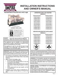
UNVENTED GAS LOG HEATER OR<br />
VENTED DECORATIVE APPLIANCE<br />
VFSR-16C-2<br />
VFSR-18C-2<br />
VFSR-24C-2<br />
VFSR-30C-2<br />
VFSR-18RAO-2<br />
VFSR-24RAO-2<br />
VFSR-30RAO-2<br />
VFSR-18RS-2<br />
VFSR-24RS-2<br />
VFSR-30RS-2<br />
MODELS<br />
VFSV-16C-2<br />
VFSV-18C-2<br />
VFSV-24C-2<br />
VFSV-30C-2<br />
VFSV-18RAO-2<br />
VFSV-24RAO-2<br />
VFSV-30RAO-2<br />
VFSV-18RS-2<br />
VFSV-24RS-2<br />
VFSV-30RS-2<br />
12359-4-0703<br />
WARNINGS<br />
If the information in this manual is not followed<br />
exactly, a fire or explosion may result causing property<br />
damage, personal injury or loss of life.<br />
– Do not store or use gasoline or other flammable<br />
vapors and liquids in the vicinity of this or any<br />
other appliance.<br />
WHAT TO DO IF YOU SMELL GAS<br />
• Do not try to light any appliance.<br />
• Do not touch any electrical switch; do not use<br />
any phone in your building.<br />
• Immediately call your gas supplier from<br />
neighbor’s phone. Follow the gas supplier’s<br />
instructions.<br />
• If you cannot reach your gas supplier, call the<br />
fire department.<br />
– Installation and service must be performed by<br />
a qualified installer, service agency or the gas<br />
supplier.<br />
EFFECTIVE DATE<br />
JULY 2003<br />
This is an unvented gas-fired heater. It uses air (<strong>oxygen</strong>)<br />
from the room in which it is installed. Provisions<br />
for adequate combustion and ventilation air must be<br />
provided. Refer to page 7.<br />
WARNING: If not installed, operated and maintained<br />
in accordance with the manufacturer's instructions,<br />
this product could expose you to substances in fuel<br />
or from fuel combustion which can cause death or<br />
serious illness.<br />
WATER VAPOR: A BY-PRODUCT OF UNVENT-<br />
ED ROOM HEATERS<br />
Water vapor is a by-product of gas combustion. An<br />
unvented room heater produces approximately one<br />
(1) ounce (30ml) of water for every 1,000 BTU's<br />
(.3KW's) of gas input per hour. Refer to page 6.<br />
Page 1
TABLE OF CONTENTS<br />
Section<br />
Page<br />
Important Safety Information .........................................................................................................................3<br />
Safety Information for Users of LP Gas ..........................................................................................................4<br />
Introduction .....................................................................................................................................................5<br />
General Information ........................................................................................................................................6<br />
Water Vapor: By Product of Unvented Room Heaters ....................................................................................6<br />
Provisions for Adequate Combustion and Ventilation Air ...............................................................................7<br />
Clearances .................................................................................................................................................... 7-8<br />
Combustible Material ......................................................................................................................................9<br />
Fireplace Preparation .......................................................................................................................................9<br />
Installing as a Vented Appliance ....................................................................................................................10<br />
Before Fully Installing the Appliance ............................................................................................................10<br />
Gas Supply .....................................................................................................................................................11<br />
Log Placement ......................................................................................................................................... 12-13<br />
Placement of Glowing Embers and Lava Rock .............................................................................................14<br />
Operation Instructions/Flame Appearance ....................................................................................................15<br />
Thermostat Operation ....................................................................................................................................15<br />
VFSV-(16, 18, 24, 30) Lighting Instructions ................................................................................................16<br />
VFSR-(16, 18, 24, 30) Lighting Instructions ................................................................................................17<br />
Pilot Flame Characteristics ...................................................................................................................... 18-19<br />
Cleaning and Servicing ..................................................................................................................................19<br />
Wiring ...........................................................................................................................................................20<br />
Troubleshooting .............................................................................................................................................21<br />
Parts List ........................................................................................................................................................22<br />
Parts View ......................................................................................................................................................23<br />
How to Order Repair Parts ............................................................................................................................23<br />
Service Notes .................................................................................................................................................24<br />
Page 2 12359-4-0703
IMPORTANT SAFETY INFORMATION<br />
• An unvented room heater having an input rating of more than<br />
6,000 Btu per hour shall not be installed in a bathroom<br />
• An unvented room heater having an input rating of more than<br />
10,000 Btu per hour shall not be installed in a bedroom or<br />
bathroom.<br />
• Never burn solid fuels in a fireplace where a gas log set is<br />
installed.<br />
• Due to high temperatures, the appliance should be located out<br />
of traffic and away from furniture and draperies.<br />
• Do not place clothing or other flammable material on or near<br />
the appliance.<br />
• Children and adults should be alerted to the hazards of high<br />
surface temperature and should stay away to avoid burns or<br />
clothing ignition.<br />
• Young children should be carefully supervised when they are<br />
in the same room as the appliance.<br />
• This unit complies with ANSI Z21.11.2b-2002 Unvented Heaters<br />
and it also complies with ANSI Z21.60b-2001 Decorative<br />
Vented Appliances for Solid Fuel Burning Fireplaces. State<br />
or local codes may only allow operation of this appliance in a<br />
vented configuration. Check your state or local codes.<br />
• Correct installation of ceramic fiber logs, proper location of<br />
the heater and annual cleaning are necessary to avoid potential<br />
problems with sooting. Sooting, resulting from improper<br />
installation or operation, can settle on surfaces outside the<br />
fireplace.<br />
• Avoid any drafts that could alter burner flame patterns. Do not<br />
allow fans to blow directly into the fireplace. Do not place a<br />
blower inside burn box area of firebox. Ceiling fans may create<br />
drafts that alter burner flame patterns. Sooting and improper<br />
burning will occur as a result of drafts.<br />
• Periodic examination and cleaning of the venting system of<br />
the solid-fuel burning fireplace, including frequency of such<br />
examination and cleaning, by a qualified agency.<br />
• The installation must conform with local codes or, in the absence<br />
of local codes, with the National Fuel Gas Code, ANSI<br />
Z223.1 (latest edition) and to the National Electrical Code,<br />
ANSI/NFPA70 (latest edition).<br />
• NOTE: Installation and repair should be done by a qualified<br />
service person. The appliance should be inspected before<br />
use and at least annually by a qualified service person. More<br />
frequent cleaning may be required due to excessive lint from<br />
carpeting, bedding material, etc. It is imperative that the control<br />
compartment, burners and circulating air passageways of the<br />
appliance be kept clean.<br />
• Any safety screen or guard removed for servicing an appliance<br />
must be replaced prior to operating the appliance. Provide<br />
adequate combustion and ventilation air.<br />
• The flow of combustion and ventilation air MUST NOT be<br />
obstructed.<br />
• Provide adequate clearances around air openings into the<br />
combustion chamber and adequate accessibility clearance for<br />
servicing and proper operation. NEVER obstruct the front<br />
opening of the appliance.<br />
• An unvented room heater intended for installation in a<br />
solid-fuel burning fireplace shall comply with the following<br />
instructions.<br />
• A fireplace screen must be in place when the appliance is<br />
operating and, unless other provisions for combustion air are<br />
provided, the screen shall have an opening(s) for introduction<br />
of combustion air.<br />
• Solid-fuels shall not be burned in a masonry or UL 127 factorybuilt<br />
fireplace in which an unvented room heater is installed.<br />
• Any glass doors shall be opened when the appliance is in<br />
operation.<br />
• Any outside air ducts and/or ash dumps in the fireplace shall<br />
be permanently closed at time of appliance installation.<br />
• WARNING: Failure to keep the primary air opening(s) of the<br />
burner(s) clean may result in sooting and property damage.<br />
When used without adequate combustion and ventilation air,<br />
heater may give off CARBON MONOXIDE, an odorless,<br />
poisonous gas.<br />
Do not install heater until all necessary provisions are made<br />
for combustion and ventilation air. Consult the written<br />
instructions provided with the heater for information<br />
concerning combustion and ventilation air. In the absence<br />
of instructions, refer to the National Fuel Gas Code, ANSI<br />
Z223.1, Section 5.3 or applicable local codes.<br />
This heater is equipped with a PILOT LIGHT SAFETY<br />
SYSTEM designed to turn off the heater if not enough fresh<br />
air is available.<br />
DO NOT TAMPER WITH PILOT LIGHT SAFETY<br />
SYSTEM!<br />
If heater shuts off, do not relight until you provide fresh air.<br />
If heater keeps shutting off, have it serviced. Keep burner and<br />
control compartment clean.<br />
WARNING<br />
CARBON MONOXIDE POISONING MAY LEAD TO<br />
DEATH.<br />
Early signs of carbon monoxide poisoning resemble the flu,<br />
with headache, dizziness and/or nausea. If you have these signs,<br />
heater may not be working properly. Get fresh air at once! Have<br />
heater serviced.<br />
Some people – pregnant women, persons with heart or lung<br />
disease, anemia, those under the influence of alcohol, those at<br />
high altitudes – are more affected by carbon monoxide than<br />
others.<br />
The pilot light safety system senses the depletion of <strong>oxygen</strong><br />
at its location. If this heater is installed in a structure having a<br />
high vertical dimension, the possibility exists that the <strong>oxygen</strong><br />
supply at the higher levels will be less than that at the heater. In<br />
this type of application, a fan to circulate the structure air will<br />
minimize this effect. The use of this fan will also improve the<br />
comfort level in the structure. When a fan is used to circulate<br />
air, it should be located so that the air flow is not directed at<br />
the burner.<br />
12359-4-0703<br />
Page 3
SAFETY INFORMATION FOR USERS OF LP-GAS<br />
Propane (LP-Gas) is a flammable gas which can cause fires and<br />
explosions. In its natural state, propane is odorless and colorless.<br />
You may not know all the following safety precautions which<br />
can protect both you and your family from an accident. Read<br />
them carefully now, then review them point by point with the<br />
members of your household. Someday when there may not be<br />
a minute to lose, everyone's safety will depend on knowing<br />
exactly what to do. If, after reading the following information,<br />
you feel you still need more information, please contact your<br />
gas supplier.<br />
LP-GAS WARNING ODOR<br />
If a gas leak happens, you should be able to smell the gas because of the odorant put in the LP-Gas.<br />
That's your signal to go into immediate action!<br />
• Do not operate electric switches, light matches, use your<br />
phone. Do not do anything that could ignite the gas.<br />
• Get everyone out of the building, vehicle, trailer, or area.<br />
Do that IMMEDIATELY.<br />
• Close all gas tank or cylinder supply valves.<br />
• LP-Gas is heavier than air and may settle in low areas such<br />
as basements. When you have reason to suspect a gas leak,<br />
keep out of basements and other low areas. Stay out until<br />
firefighters declare them to be safe.<br />
NO ODOR DETECTED - ODOR FADE<br />
Some people cannot smell well. Some people cannot smell the there is rust inside the storage tank or in iron gas pipes.<br />
odor of the chemical put into the gas. You must find out if you<br />
The odorant in escaped gas can adsorb or absorb onto or into<br />
can smell the odorant in propane. Smoking can decrease your<br />
walls, masonry and other materials and fabrics in a room. That<br />
ability to smell. Being around an odor for a time can affect your<br />
will take some of the odorant out of the gas, reducing its odor<br />
sensitivity or ability to detect that odor. Sometimes other odors<br />
intensity.<br />
in the area mask the gas odor. People may not smell the gas odor<br />
or their minds are on something else. Thinking about smelling LP-Gas may stratify in a closed area, and the odor intensity<br />
a gas odor can make it easier to smell.<br />
could vary at different levels. Since it is heavier than air, there<br />
may be more odor at lower levels. Always be sensitive to the<br />
The odorant in LP-gas is colorless, and it can fade under some<br />
slightest gas odor. If you detect any odor, treat it as a serious<br />
circumstances. For example, if there is an underground leak, the<br />
leak. Immediately go into action as instructed earlier.<br />
movement of the gas through soil can filter the odorant. Odorants<br />
in LP-Gas also are subject to oxidation. This fading can occur if<br />
• Learn to recognize the odor of LP-gas. Your local LP-Gas<br />
Dealer can give you a "Scratch and Sniff" pamphlet. Use it<br />
to find out what the propane odor smells like. If you suspect<br />
that your LP-Gas has a weak or abnormal odor, call your<br />
LP-Gas Dealer.<br />
• If you are not qualified, do not light pilot lights, perform<br />
service, or make adjustments to appliances on the LP-Gas<br />
system. If you are qualified, consciously think about the<br />
odor of LP-Gas prior to and while lighting pilot lights or<br />
performing service or making adjustments.<br />
• Sometimes a basement or a closed-up house has a musty<br />
smell that can cover up the LP-Gas odor. Do not try to light<br />
pilot lights, perform service, or make adjustments in an area<br />
where the conditions are such that you may not detect the<br />
odor if there has been a leak of LP-Gas.<br />
• Odor fade, due to oxidation by rust or adsorption on walls<br />
of new cylinders and tanks, is possible. Therefore, people<br />
should be particularly alert and careful when new tanks or<br />
cylinders are placed in service. Odor fade can occur in new<br />
tanks, or reinstalled old tanks, if they are filled and allowed<br />
SOME POINTS TO REMEMBER<br />
• Use your neighbor's phone and call a trained LP-Gas service<br />
person and the fire department. Even though you may not<br />
continue to smell gas, do not turn on the gas again. Do not<br />
re-enter the building, vehicle, trailer, or area.<br />
• Finally, let the service man and firefighters check for escaped<br />
gas. Have them air out the area before you return. Properly<br />
trained LP-Gas service people should repair the leak, then<br />
check and relight the gas appliance for you.<br />
to set too long before refilling. Cylinders and tanks which<br />
have been out of service for a time may develop internal rust<br />
which will cause odor fade. If such conditions are suspected<br />
to exist, a periodic sniff test of the gas is advisable. If you<br />
have any question about the gas odor, call your LP-gas dealer.<br />
A periodic sniff test of the LP-gas is a good safety measure<br />
under any condition.<br />
• If, at any time, you do not smell the LP-Gas odorant and you<br />
think you should, assume you have a leak. Then take the same<br />
immediate action recommended above for the occasion when<br />
you do detect the odorized LP-Gas.<br />
• If you experience a complete "gas out," (the container is under<br />
no vapor pressure), turn the tank valve off immediately.<br />
If the container valve is left on, the container may draw in<br />
some air through openings such as pilot light orifices. If this<br />
occurs, some new internal rusting could occur. If the valve is<br />
left open, then treat the container as a new tank. Always be<br />
sure your container is under vapor pressure by turning it off<br />
at the container before it goes completely empty or having<br />
it refilled before it is completely empty.<br />
Page 4 12359-4-0703
IMPORTANT: Read all instructions carefully before starting installation.<br />
Failure to follow these installation instructions may result in a possible<br />
fire hazard and will void the warranty.<br />
Save this manual for future reference.<br />
Please read this manual before installing and using the appliance.<br />
Instructions to Installer<br />
1. Installer must leave instruction manual with owner after installation.<br />
2. Installer must have owner fill out and mail warranty card supplied with<br />
unvented room heater/vented decorative appliance.<br />
3. Installer should show owner how to start and operate unvented room<br />
heater/vented decorative appliance.<br />
Always consult your local Building Department regarding regulations,<br />
codes or ordinances which apply to the installation of an unvented room<br />
heater/vented decorative appliance.<br />
This appliance may be installed in an aftermarket* manufactured (mobile)<br />
home, where not prohibited by state or local codes.<br />
*Aftermarket: Completion of sale, not for purpose of resale, from the<br />
manufacturer.<br />
This appliance is only for use with the type of gas indicated on the rating<br />
plate. This appliance is not convertible for use with other gases.<br />
New Installation<br />
VFSV Model - variable does not operate-ON is OFF/OFF is ON-wires<br />
into the back of receiver are reversed.<br />
Solid-fuels shall not be burned in a fireplace where a vented decorative<br />
appliance is installed.<br />
A vented decorative appliance must be installed only in a solid-fuel<br />
burning fireplace with a working flue and constructed of non-combustible<br />
material.<br />
Any alteration of the original design, installed other than as shown in these<br />
instructions or use with a type of gas not shown on the rating plate is the<br />
responsibility of the person and company making the change.<br />
Important<br />
All correspondence should refer to complete Model Number, Serial Number<br />
and type of gas.<br />
Natural Gas Variable Millivolt<br />
Regulator pressure setting 3.5" W.C. 3.5" W.C.<br />
Gas inlet pressure Max. 10.5" W.C. Max. 10.5" W.C.<br />
Min. 5.0" W.C. Min. 5.0" W.C.<br />
INTRODUCTION<br />
PRODUCT SPECIFICATION<br />
Attention: During initial use of ceramic log you will detect an odor as the<br />
ceramic log is cured.<br />
Notice: During initial firing of this unit, its paint will bake out, and smoke<br />
will occur. To prevent triggering of smoke alarms, ventilate the room in<br />
which the unit is installed.<br />
WARNING: This appliance is for installation only in a solid-fuel<br />
burning masonry or UL 127 factory-built fireplace or in a listed ventless<br />
firebox enclosure. It has been design certified for these installations.<br />
Exception: DO NOT install this appliance in a factory-built fireplace<br />
that includes instructions stating it has not been tested or should not<br />
be used with unvented gas logs.<br />
WARNING: Any modification to this unvented gas heater or its<br />
controls can be dangerous. Improper installation or use of the heater<br />
can cause serious injury or death from fire, burns, explosion or carbon<br />
monoxide poisoning.<br />
Well Head Gas Installations<br />
Some natural gas utilities use "well head" gas. This may affect the Btu output<br />
of the unit. Contact the gas company for the heating value. Contact the<br />
manufacturer or your gas company before changing spud/orifice size.<br />
ACCESSORIES<br />
Description<br />
Color<br />
For use with VFSV and VFSR models<br />
EK-1 Embers Kit<br />
ELH-1 Fireplace Hood for Vent-Free Logs Black<br />
ELH-2 Fireplace Hood for Vent-Free Logs Brass<br />
For use with VFSR models only<br />
FRBC-1 Battery Operated Remote Control<br />
FRBTC-1 Battery Operated Remote Control with Thermostat<br />
FREC-1 Electric Remote Control<br />
FWS-1 Wall Switch<br />
GWSG-T Wall Thermostat, Millivolt<br />
Propane Gas Variable Millivolt<br />
Regulator pressure setting 10.0" W.C. 10.0" W.C<br />
Gas inlet pressure Max 13.0" W.C. Max. 13.0" W.C.<br />
Min. 11.0" W.C. Min. 11.0" W.C.<br />
MODEL GAS TYPE VALVE TYPE BTUH MAX. RATE BTUH MIN. RATE<br />
VFSV-16 Natural Variable 25,000 17,500<br />
VFSV-16 Propane Variable 22,500 15,750<br />
VFSR-16 Natural Millivolt 25,000 17,500<br />
VFSR-16 Propane Millivolt 22,500 15,750<br />
VFSV-18 Natural Variable 32,000 19,000<br />
VFSV-18 Propane Variable 32,000 19,000<br />
VFSR-18 Natrual Millivolt 32,000 22,000<br />
VFSR-18 Propane Millivolt 32,000 22,000<br />
VFSV-24 Natural Variable 36,000 20,000<br />
VFSV-24 Propane Variable 36,000 20,000<br />
VFSR-24 Natural Millivolt 36,000 25,000<br />
VFSR-24 Propane Millivolt 36,000 25,000<br />
VFSV-30 Natural Variable 38,000 20,000<br />
VFSV-30 Propane Variable 38,000 20,000<br />
12359-4-0703<br />
Page 5
GENERAL INFORMATION<br />
This is an unvented gas-fired heater. It uses air (<strong>oxygen</strong>) from the<br />
room in which it is installed. Provisions for adequate combustion<br />
and ventilation air must be provided.<br />
Keep room area clear and free from combustible materials,<br />
gasoline and other flammable vapors and liquids.<br />
Unvented gas heaters are a supplemental zone heater. They are not<br />
intended to be a primary heating appliance. Water vapor produced<br />
by an unvented heater can create moisture problems in a home<br />
when operated for extended periods of time.<br />
During manufacturing, fabricating and shipping, various<br />
components of this appliance are treated with certain oils, films or<br />
bonding agents. These chemicals are not harmful but may produce<br />
annoying smoke and smells as they are burned off during the initial<br />
operation of the appliance; possibly causing headaches or eye or<br />
lung irritation. This is a normal and temporary occurrence.<br />
The initial break-in operation should last 2-3 hours with the burner<br />
at the highest setting. Provide maximum ventilation by opening<br />
windows or doors to allow odors to dissipate. Any odors remaining<br />
after this initial break-in period will be slight and will disappear<br />
with continued use.<br />
This appliance must not be used with glass doors in the closed<br />
position. This can lead to pilot outages and severe sooting outside<br />
the fireplace.<br />
Do not use this room heater if any part has been under water.<br />
Immediately call a qualified service technician to inspect the<br />
room heater and replace any part of the control system and any<br />
gas control which has been under water.<br />
Before you get started<br />
Carefully inspect the contents for shipping damage. If any parts are<br />
missing or damaged, immediately inform the dealer from whom<br />
you purchased the appliance. Do not attempt to install any part of<br />
the appliance unless you have all parts in good condition.<br />
Metal shipping plate covering burner marked REMOVE must be<br />
removed from top of burner and discarded. Burner will not operate<br />
if plate is left in place.<br />
Make sure you have received all parts:<br />
Check your packing list to verify that all listed parts have been<br />
received. You should have the following:<br />
• Gas log grate/burner assembly.<br />
• VFS(V,R)-(16, 18, 24, 30)C; 16", 18", 24" and 30" logs, five<br />
(5) ceramic fiber logs.<br />
• VFS(V,R)-(18, 24, 30)RAO; 18", 24" and 30" logs, seven (7)<br />
refractory logs.<br />
• VFS(V,R)-(18, 24, 30)RS; 18", 24" and 30" logs, six (6)<br />
refractory logs.<br />
• Two (2) masonry anchoring screws and two (2) 10 x 1/2" black<br />
sheet metal anchoring screws.<br />
• Plastic bag containing glowing embers (rock wool) for burner<br />
coverage.<br />
• Plastic bag containing lava rock.<br />
Millivolt controlled heater designed to be operated with optional<br />
devices for ON/OFF functions.<br />
• Wall switch or thermostat with wire.<br />
• Hand held remote control with ON/OFF switch or<br />
thermostat.<br />
Handle the gas log burner assembly by the grate and legs only.<br />
Do not pick the unit up by the burner.<br />
Gloves are recommended when handling ceramic fiber logs to<br />
prevent skin irritation from loose fibers. Logs are fragile - Handle<br />
with care.<br />
Qualified Installing Agency<br />
Installation and replacement of gas piping, gas utilization equipment<br />
or accessories and repair and servicing of equipment shall<br />
be performed only by a qualified agency. The term "qualified<br />
agency" means any individual, firm, corporation, or company<br />
that either in person or through a representative is engaged in and<br />
is responsible for (a) the installation, testing, or replacement of<br />
gas piping or (b) the connection, installation, testing, repair, or<br />
servicing of equipment; that is experienced in such work; that is<br />
familiar with all precautions required, and that has complied with<br />
all the requirements of the authority having jurisdiction.<br />
State of Massachusetts: The installation must be made by<br />
a licensed plumber or gas fitter in the Commonwealth of<br />
Massachusetts.<br />
The installation must conform with local codes or, in the absence of<br />
local codes, with the National Fuel Gas Code, ANSI Z223.1.*<br />
*Available from the American National Standards Institute, Inc. 11 West 42nd<br />
St., New York, N.Y. 10018.<br />
High Altitudes: For altitudes/elevation above 2,000 feet ratings<br />
should be reduced at the rate of 4 percent for each 1,000 feet above<br />
sea level. Contact the manufacturer.<br />
WATER VAPOR: A BY-PRODUCT OF UNVENTED ROOM HEATERS<br />
Water vapor is a by-product of gas combustion. An unvented room<br />
heater produces approximately one (1) ounce (30ml) of water for<br />
every 1,000 BTU's (.3KW's) of gas input per hour.<br />
Unvented room heaters are recommended as supplemental heat (a<br />
room) rather than a primary heat source (an entire house). In most<br />
supplemental heat applications, the water vapor does not create a<br />
problem. In most applications, the water vapor enhances the low<br />
humidity atmosphere experienced during cold weather.<br />
The following steps will help insure that water vapor does not<br />
become a problem.<br />
1. Be sure the heater is sized properly for the application, including<br />
ample combustion air and circulation air.<br />
2. If high humidity is experienced, a dehumidifier may be used<br />
to help lower the water vapor content of the air.<br />
3. Do not use an unvented room heater as the primary heat<br />
Page 6 12359-4-0703
PROVISIONS FOR ADEQUATE COMBUSTION & VENTILATION AIR<br />
This heater shall not be installed in a confined space unless provisions<br />
are provided for adequate combustion and ventilation air.<br />
The National Fuel Gas Code defines a confined space as a space whose<br />
volume is less than 50 cubic feet per 1,000 Btu per hour (4.8m 3 per kw)<br />
of the aggregate input rating of all appliances installed in that space and<br />
an unconfined space as a space whose volume is not less than 50 cubic<br />
feet per 1,000 Btu per hour (4.8 m 3 per kw) of the aggregate input rating<br />
of all appliances installed in that space. Rooms communicating directly<br />
with the space in which the appliances are installed, through openings<br />
not furnished with doors, are considered a part of the unconfined space.<br />
Unusually Tight Construction<br />
The air that leaks around doors and windows may provide enough fresh<br />
air for combustion and ventilation. However, in buildings of unusually<br />
tight construction, you must provide additional fresh air.<br />
Unusually tight construction is defined as construction where:<br />
a. Walls and ceilings exposed to the outside atmosphere have a<br />
continuous water vapor retarder with a rating of one perm or less<br />
with openings gasketed or sealed, and<br />
b. Weatherstripping has been added on openable windows and doors,<br />
and<br />
c. Caulking or sealants are applied to areas such as joints around<br />
window and door frames, between sole plates and floors, between<br />
wall-ceiling joints, between wall panels, at penetrations for plumbing,<br />
electrical, and gas lines, and at other openings.<br />
If your home meets all of the three criteria above, you must provide<br />
additional fresh air.<br />
Warning: If the area in which the heater may be operated is smaller than<br />
that defined as an unconfined space or if the building is of unusually tight<br />
construction, provide adequate combustion and ventilation air by one<br />
of the methods described in the National Fuel Gas Code, ANSI Z223.1,<br />
Section 5.3. or applicable local codes.<br />
Example of Large Room with 1/2 Wall divider.<br />
Figure 1<br />
The following formula can be used to determine the maximum heater<br />
rating per the definition of unconfined space:<br />
Btu/Hr = (L + L )FT x (W)FT x (H)FT 1 2<br />
x 1000<br />
50<br />
If the area in which the heater may be operated is smaller than that defined<br />
as an unconfined space, provide adequate combustion and ventilation air<br />
by one of the methods described in the National Fuel Gas Code, ANSI<br />
Z223.1, Section 5.3.<br />
Adhere to all codes, or in their absence, the latest edition of THE<br />
NATIONAL FUEL GAS CODE ANSI Z223.1 or NFPA54 which can<br />
be obtained from:<br />
American National Standards Institute National Fire Protection Association,<br />
Inc.<br />
11 West 42nd St. Batterymarch Park<br />
CLEARANCES<br />
Minimum Dimensions For Solid Fuel Burning Fireplaces UL127<br />
Factory Built Fireplaces (Figure 2)<br />
Model A B C D<br />
VFSV-16 18" 11 1/2" 24" 18"<br />
VFSR-16 18" 11 1/2" 24" 18"<br />
VFSV-18 17" 14" 28" 17"<br />
VFSR-18 17" 14" 28" 17"<br />
VFSV-24 23" 14" 30" 18"<br />
VFSR-24 23" 14" 30" 18"<br />
VFSV-30 26" 14" 34" 20"<br />
VFSR-30 26" 14" 34" 20"<br />
The dimensions shown and defined in the fireplace manufacturer’s<br />
instructions are minimum clearances to maintain in installing this<br />
heater. Left and right clearances are determined when facing the<br />
front of the heater.<br />
Follow these instructions to ensure safe installation.<br />
Failure to follow instructions exactly can create a fire hazard.<br />
12359-4-0703<br />
Figure 2<br />
Page 7
CLEARANCES (continued)<br />
Sidewall & Ceiling Clearances (Figure 3)<br />
18", 24", 30" Log 41"<br />
16" Log 36"<br />
Figure 3<br />
The sides of the fireplace opening must be 6" from any combustible wall.<br />
The ceiling must be at least 36" (for the 16" log) and 41" (for 18", 24"<br />
and 30" logs) from the fireplace opening.<br />
Mantel Clearances Without Hood (Figure 4)<br />
You must have non-combustible materials above the fireplace opening.<br />
Non-combustible material must extend at least 12" above fireplace<br />
opening. With sheet metal, you must have non-combustible material<br />
behind it.<br />
Heat resistant materials such as slate and marble must be at least 1/2"<br />
thick. Sheet metal should not be installed onto combustible material.<br />
Non-Combustible Requirements for<br />
Material Distance Safe Installation<br />
12" or more Non-combustible material.<br />
Less than 12" Non-combustible material must be extended to<br />
at least 8" with the installation of the optional<br />
fireplace hood. If you cannot extend noncombustible<br />
material at least 8", you must<br />
operate heater with flue damper open.<br />
Mantel Clearances with Hood (Figure 5)<br />
You must have non-combustible materials above the fireplace opening.<br />
Non-combustible material must extend at least 8" above fireplace opening.<br />
With sheet metal, you must have non-combustible material behind it.<br />
Heat resistant materials such as slate and marble must be at least 1/2"<br />
thick. Sheet metal should not be installed onto combustible material.<br />
Example: A mantel may project from the wall a maximum of 2" at a minimum<br />
of 13-1/2" above the opening, and a maximum of 6" at a minimum<br />
of 15" above the opening.<br />
HEAT RESISTANT<br />
MATERIAL<br />
8" WITH HOOD<br />
8" Mantel<br />
6" Mantel<br />
4" Mantel<br />
2" Mantel<br />
14.25" 16.0"<br />
13.5" 15.0"<br />
HEAT RESISTANT<br />
MATERIAL<br />
12" WITHOUT<br />
HOOD<br />
10" and less Mantel<br />
12"<br />
28"<br />
HEATER IN FIREPLACE<br />
OR FIREBOX<br />
Figure 5<br />
HOOD<br />
HEATER IN<br />
FIREPLACE<br />
OR FIREBOX<br />
If your installation does not meet the above minimum clearances, you<br />
must proceed to one of the following steps:<br />
• Operate the heater with the flue damper open. See page 10 for Installing<br />
as a Vented Appliance.<br />
• Raise the mantel to the proper height.<br />
• Remove the mantel.<br />
Floor Clearance (Figure 6)<br />
If installing heater at floor level, the minimum distance to combustibles<br />
is “0” inches.<br />
Figure 6<br />
Figure 4<br />
If your installation does not meet the above clearances, you must proceed<br />
to one of the following steps:<br />
• Use a hood<br />
• Operate the heater with flue damper open. See page 10 for Installing<br />
as a Vented Appliance.<br />
• Raise the mantel to the proper height.<br />
• Remove the mantel.<br />
Page 8 12359-4-0703
COMBUSTIBLE MATERIAL<br />
Do not attach combustible material to the mantel of your fireplace. This<br />
is a fire hazard.<br />
No greeting card, stockings or ornamentation of any type should be<br />
placedon or attached to the fireplace. This is a heating appliance. The<br />
flow of heat can ignite combustibles.<br />
Figure 7<br />
Figure 8<br />
FIREPLACE PREPARATION<br />
• Turn off gas supply to fireplace or firebox.<br />
• Have the fireplace floor and chimney professionally cleaned to remove<br />
ashes, soot, creosote or other obstructions.<br />
Have this cleaning performed annually after installation.<br />
• Seal any fresh air vents or ash clean-out doors located on floor or wall<br />
of fireplace. If not, drafting may cause pilot<br />
outage or sooting. Use a heat-resistant sealant. Do not seal chimney<br />
flue damper.<br />
Install and operate the appliance as directed in this manual.<br />
FOR FACTORY BUILT FIREPLACES<br />
FREE OPENING AREA OF CHIMNEY DAMPER FOR VENTING<br />
COMBUSTION PRODUCTS FROM DECORATIVE APPLIANCES<br />
FOR INSTALLATION IN SOLID FUEL BURNING FIREPLACES<br />
12359-4-0703<br />
Appliance Input Rate (BTU/hr)<br />
20 30 40<br />
Chimney<br />
Height*<br />
Minimum Opening** (sq. in.)<br />
(ft)<br />
10 11.3 16.6 22.1<br />
15 8.6 12.6 17.3<br />
20 7.5 10.8 14.5<br />
25 6.6 9.6 12.6<br />
30 6.2 9.1 11.3<br />
35 5.7 8.0 10.8<br />
40 5.3 7.5 10.2<br />
* Height is from hearth to top of chimney and the minimum height is<br />
10 feet.<br />
** Chart shows minimum opening (sq. in.) for given height and input<br />
rate.<br />
FOR MASONRY BUILT FIREPLACES<br />
FREE OPENING AREA OF CHIMNEY DAMPER FOR VENTING<br />
COMBUSTION PRODUCTS FROM DECORATIVE APPPLIANCES<br />
FOR INSTALLATION IN SOLID FUEL BURNING FIREPLACES<br />
Appliance Input Rate (BTU/hr)<br />
20 30 40<br />
Chimney<br />
Height*<br />
Minimum Opening** (sq. in.)<br />
(ft)<br />
6 17.6 25.7 33.8<br />
8 16.5 23.7 31.2<br />
10 15.1 21.7 28.7<br />
15 14.1 19.9 26.1<br />
20 12.9 18.5 23.7<br />
30 12.2 16.9 21.6<br />
* Height is from hearth to top of chimney and the minimum height is<br />
6 feet.<br />
** Chart shows minimum opening (sq. in.) for given height and input<br />
rate.<br />
Page 9
INSTALLING AS A VENTED APPLIANCE<br />
Damper Stop Installation<br />
Figure 9<br />
Manual and millivolt controlled gas logs may be installed as<br />
a vented decorative log set in compliance with ANSI Z21.60<br />
and National Fuel Gas Code, Section 6.6 since, the gas logs are<br />
operated with the damper open, non-combustible material and<br />
minimum mantel requirements do not apply.<br />
This appliance is for installation only in a solid fuel burning<br />
fireplace (masonry fireplace or manufactured fireplace) with a<br />
working flue and constructed of noncombustible material.<br />
Damper stop installation:<br />
A damper stop must be provided with the unit. Contact your<br />
dealer to obtain one. The damper stop must be installed as shown<br />
in (Figure 9) to prevent full closure of the fireplace damper blade<br />
and provide a minimum 29 square inch flue opening.<br />
State of Massachusetts requirement for installation of vented<br />
decorative appliance in a vented fireplace is the following:<br />
A vented decorative gas appliance must be installed in a vented<br />
fireplace only in the state of Massachusetts. The vent damper<br />
must be removed or welded permanently open.<br />
BEFORE FULLY INSTALLING THE APPLIANCE<br />
• Turn off the gas supply to the fireplace or firebox.<br />
• Seal any fresh air vents and/or ash clean-out doors located on<br />
the floor or wall of the fireplace. If left unsealed, drafting may<br />
cause pilot outage or sooting. Use a heat resistant sealant. Do<br />
not seal the chimney flue damper.<br />
Before installing in a solid fuel burning fireplace, the chimney<br />
flue and firebox must be cleaned of soot, creosote, ashes and loose<br />
paint by a qualified chimney cleaner.<br />
You must secure the gas log heater to the fireplace floor. If<br />
not, the entire unit may move when you adjust the controls.<br />
Movement of unit may cause shifting of the gas logs which<br />
leads to sooting and improper burning. Grate movement could<br />
cause a gas leak.<br />
Special care is required if you are installing the unit into a<br />
sunken fireplace. You must raise the fireplace floor to allow<br />
access to gas log controls. This will insure adequate air flow<br />
and guard against sooting. Raise the fireplace floor using<br />
noncombustible materials.<br />
Assembly Procedure: (Figure 10)<br />
1. Center the gas log unit in the fireplace or firebox. Make certain<br />
the front feet of the grate sit inside the front edge of the<br />
fireplace or firebox.<br />
2. An anchor hole is provided in the two bottom side members of<br />
the grate frame. After centering the grate correctly, mark the<br />
hole positions on the fireplace/firebox floor. Drill two (2) 5/32"<br />
diameter holes approximately 1-1/2" deep for masonry screws<br />
or 1/8" hole for sheet metal screws.<br />
3. Anchor the grate to the fireplace/firebox floor using the screws<br />
provided. Refer to Figure10.<br />
Proper installation of the grate is essential to prevent any movement<br />
of the gas logs and controls during operation.<br />
Figure 10<br />
Page 10 12359-4-0703
GAS SUPPLY<br />
Check all local codes for requirements, especially for the size and<br />
type of gas supply line required.<br />
Recommended Gas Pipe Diameter<br />
Pipe Length Schedule 40 Pipe Tubing, Type L<br />
(Feet) Inside Diameter Outside Diameter<br />
Nat. L.P. Nat. L.P.<br />
0-10 1/2" 3/8" 1/2" 3/8"<br />
1.3 cm 1.0 cm 1.3 cm 1.0cm<br />
10-40 1/2" 1/2" 5/8" 1/2"<br />
1.3 cm 1.3 cm 1.6 cm 1.3cm<br />
40-100 1/2" 1/2" 3/4" 1/2"<br />
1.3 cm 1.3 cm 1.9 cm 1.3cm<br />
100-150 3/4" 1/2" 7/8" 3/4"<br />
1.9 cm 1.3 cm 2.2 cm 1.9cm<br />
Note: Never use plastic pipe. Check to confirm whether your local<br />
codes allow copper tubing or galvanized.<br />
Note: Since some municipalities have additional local codes,<br />
it is always best to consult your local authority and installation<br />
code.<br />
Installing a New Main Gas Cock<br />
Each appliance should have its own manual gas cock.<br />
In the state of Massachusetts the gas cock must be a T handle<br />
type.<br />
A manual main gas cock should be located in the vicinity of<br />
the unit. Where none exists, or where its size or location is not<br />
adequate, contact your local authorized installer for installation<br />
or relocation.<br />
Compounds used on threaded joints of gas piping shall be resistant<br />
to the action of liquefied petroleum gases. The gas lines must be<br />
checked for leaks by the installer. This should be done with a soap<br />
solution watching for bubbles on all exposed connections, and if<br />
unexposed, a pressure test should be made.<br />
Never use an exposed flame to check for leaks. Appliance must be<br />
disconnected from piping at inlet of control valve and pipe capped<br />
or plugged for pressure test. Never pressure test with appliance<br />
connected; control valve will sustain damage!<br />
A gas valve and ground joint union should be installed in the gas<br />
line upstream of the gas control to aid in servicing. It is required<br />
by the National Fuel Gas Code that a drip line be installed near<br />
the gas inlet. This should consist of a vertical length of pipe tee<br />
connected into the gas line that is capped on the bottom in which<br />
condensation and foreign particles may collect.<br />
Figure 11<br />
The use of the following gas connectors is recommended:<br />
— ANS Z21.24 Appliance Connectors of Corrugated Metal<br />
Tubing and Fittings<br />
— ANS Z21.45 Assembled Flexible Appliance Connectors of<br />
Other Than All-Metal Construction<br />
The above connectors may be used if acceptable by the authority<br />
having jurisdiction. The state of Massachusetts requires that a<br />
flexible appliance connector cannot exceed three feet in length.<br />
Pressure Testing of the Gas Supply System<br />
1. To check the inlet pressure to the gas valve, a 1/8" (3.175mm)<br />
N.P.T. plugged tapping, accessible for test gauge connection,<br />
must be placed immediately upstream of the gas supply<br />
connection to the appliance.<br />
2. The appliance and its individual shutoff valve must be<br />
disconnected from the gas supply piping system during any<br />
pressure testing of that system at test pressures in excess of<br />
1/2 psig (3.5 kPa).<br />
3. The appliance must be isolated from the gas supply piping<br />
system by closing its individual manual shutoff valve during<br />
any pressure testing of the gas supply piping system at test<br />
pressures equal to or less than 1/2 psig (3.5 kPa).<br />
Attention! If one of the procedures results in pressures in excess<br />
of 1/2 psig (14" w.c.) (3.5 kPa) on the appliance gas valve, it will<br />
result in a hazardous condition.<br />
12359-4-0703<br />
Page 11
LOG PLACEMENT<br />
VFSR and VFSV-(16, 18, 24, 30)C<br />
Before you begin: This unit is supplied with a set of five ceramic<br />
fiber logs. Do not, handle these logs with your bare hands! Always<br />
wear gloves to prevent skin irritation from ceramic fibers. After<br />
handling logs, wash your hands gently with soap and water to<br />
remove any traces of fibers.<br />
Every burner has a shipping plate on burner pan. This shipping<br />
plate must be removed before log placement.<br />
All Logs<br />
The positioning of the logs is critical to the safe and clean operation<br />
of this heater. Sooting and other problems may result if the logs<br />
are not properly and firmly positioned in the appliance.<br />
Refer to Figures 12 , 13, 14 and 15 for the following warning.<br />
3. Place rear (#1) log onto right, rear pin on rear log support.<br />
4. Place middle (#2) log between rear log support and burner<br />
pan.<br />
5. Place left, front (#3) log onto two (2) left, front pins on burner<br />
pan.<br />
6. Place right, front (#4) log onto two (2) right, front pins on<br />
burner pan.<br />
7. Place branch (#5) log onto two (2) pins on middle (#2) log.<br />
Attention: On 16" log set, middle (#2) log has one (1) pin.<br />
8. Log placement is completed.<br />
Attention: Do not use Figure 13 to order logs. Refer to Page<br />
22, Parts List and Page 23, Parts View to order logs for your<br />
appropriate model number.<br />
Warning: Failure to position the parts in accordance with this<br />
diagram or failure to use only parts specifically approved with<br />
this appliance may result in property damage or personal<br />
injury.<br />
PROPER INSTALLATION SEQUENCE:<br />
VFSR and VFSV-(16, 18, 24, 30)C (Figures 12 and 13)<br />
1. Remove shipping plate from burner pan.<br />
2. Place two (2) log grates onto two (2) left, front pins and two<br />
(2) right, front pins on burner pan.Secure grates with two (2)<br />
Tinnerman clips.<br />
Log Placement<br />
VFSR and VFSV-(16, 18, 24, 30)C Logs<br />
Figure 13<br />
Figure 12<br />
Page 12 12359-4-0703
PROPER INSTALLATION SEQUENCE:<br />
VFSR and VFSV-(18, 24, 30)RAO (Figures 12 and 14)<br />
1. Remove shipping plate from burner pan.<br />
2. Place two (2) log grates onto two (2) left, front pins and two<br />
(2) right, front pins on burner pan. Secure grates with two<br />
(2) Tinnerman clips.<br />
3. Place right, rear (#1) log onto right, rear pin on rear log<br />
support.<br />
4. Place left, rear (#2) log onto left, rear pin on rear log<br />
support.<br />
5. Place left, front (#3) log onto two (2) left, front pins on burner<br />
pan.<br />
6. Place right, front (#4) log onto two (2) right, front pins on<br />
burner pan.<br />
7. Insert boss on top, middle (#5) log into recess on right side<br />
of left, rear (#2) log.<br />
8. Insert boss on top, left (#6) log into recess on left side of left,<br />
rear (#2) log and onto left side of left, front (#3) log.<br />
9. Insert boss on top, right (#7) log into recess on right side of<br />
right, rear (#1) log and onto right side of right, front (#4)<br />
log.<br />
10. Log placement is completed.<br />
Attention: Do not use Figure 14 to order logs. Refer to Page<br />
22, Parts List and Page 23, Parts View to order logs for your<br />
appropriate model number.<br />
PROPER INSTALLATION SEQUENCE:<br />
VFSR and VFSV-(18, 24, 30)RS (Figures 12 and 15)<br />
1. Remove shipping plate from burner pan.<br />
2. Place two (2) log grates onto two (2) left, front pins and two<br />
(2) right, front pins on burner pan.Secure grates with two (2)<br />
Tinnerman clips.<br />
3. Place left rear (#1) log onto left, rear pin on rear log support.<br />
4. Place right, rear (#2) log onto right, rear pin on rear log<br />
support.<br />
5. Place left, front (#3) log onto two (2) left, front pins on burner<br />
pan.<br />
6. Place right, front (#4) log onto two (2) right, front pins on<br />
burner pan.<br />
7. Insert boss on top, left (#5) log into recess on left side of left,<br />
rear (#1) log and onto left side of left, front (#3) log.<br />
8. Insert boss on top, right (#6) log into recess on right side of<br />
left, front (#3) log.<br />
9. Log placement is completed.<br />
Attention: Do not use Figure 15 to order logs. Refer to Page<br />
22, Parts List and Page 23, Parts View to order logs for your<br />
appropriate model number.<br />
Log Placement<br />
VFSR and VFSV-(18, 24, 30)RAO Logs<br />
Figure 14<br />
Log Placement<br />
VFSR and VFSV-(18, 24, 30)RS Logs<br />
Figure 15<br />
12359-4-0703<br />
Page 13
PLACEMENT OF GLOWING EMBERS AND LAVA ROCK<br />
Provided with the log set is a small bag of glowing embers (rock<br />
wool) to be placed between logs on the flat metal surface of the<br />
burner.<br />
TOP VIEW OF LOG SET<br />
REAR LOG<br />
Placement of Glowing Embers (rock wool)<br />
For Charred Oak (C) Logs<br />
Figure 16<br />
Placement of Glowing Embers (rock wool)<br />
For Refractory Sassafras (RS) Logs<br />
Figure 18<br />
Placement of the glowing embers (rock wool) is very individual<br />
and light coverage of the areas indicated will provide your best<br />
effects. We recommend separation of the rock wool by hand and<br />
make your coverage as light and fluffy as possible.<br />
Place just enough embers on the burner to obtain the glow and a<br />
gold yellow flame.<br />
Do not place embers (rock wool) over large ports in rear portion<br />
of burner.<br />
A thin layer of glowing embers (rock wool) should be placed under<br />
open space between the right and left middle logs.<br />
Rock wool should not be placed in the area of the pilot assembly.<br />
Placing Lava Rock in Front of Grate and Burner Pan on Fireplace<br />
Floor<br />
Spread lava rocks on fireplace floor in front of grate and burner<br />
pan. The lava rocks are for decorative effect and are not required<br />
for fireplace operation.<br />
Placement of Glowing Embers (rock wool)<br />
For Refractory Aged Oak (RAO) Logs<br />
Figure 17<br />
ATTENTION: DO NOT PLACE LAVA ROCKS ON LOGS<br />
OR ROCK WOOL. THE LAVA ROCKS SHOULD ONLY<br />
BE PLACED ON THE FIREPLACE FLOOR.<br />
Page 14 12359-4-0703
OPERATION INSTRUCTIONS/FLAME APPEARANCE<br />
Flames from the pilot (rear right back side of the pan burner) as<br />
well as the main flame should be visually checked as the log set<br />
is installed.<br />
In normal operation at full rate after 10 to 15 minutes, the flame<br />
appearance should be sets of yellow flames.<br />
NOTE: all flames will be random by design, flame height will<br />
go up and down.<br />
Glowing embers (rock wool) can cover the pan burner in between<br />
the front and middle logs, but very little is necessary to cover this<br />
area. Excess ember material causes the yellow flame to become<br />
orange and stringy. Apply just enough to obtain slow glow and a<br />
gold yellow flame.<br />
Avoid any drafts that alter burner flame patterns. Do not allow<br />
fans to blow directly into fireplace. Do not place a blower inside<br />
the burner area of the firebox. Ceiling fans may create drafts that<br />
alter flame patterns. Sooting and improper burning will result.<br />
During manufacturing, fabricating and shipping, various<br />
components of this appliance are treated with certain oils, films or<br />
bonding agents. These chemicals are not harmful, but may produce<br />
annoying smoke and smells as they are burned off during the initial<br />
operation of the appliance, possibly causing headaches or eye or<br />
lung irritation. This is a normal and temporary occurrence.<br />
The initial break-in operation should last 2-3 hours with the burner<br />
at the highest setting. Provide maximum ventilation by opening<br />
windows or doors to allow odors to dissipate. Any odors remaining<br />
after this initial break-in will be slight and will disappear with<br />
continued use.<br />
Variable - Figure 19<br />
Millivolt - Figure 20<br />
THERMOSTAT OPERATION<br />
Variable Control has five (5) positions<br />
Off – All gas to set is completely off at the valve.<br />
Pilot – Valve position to light/maintain the standing<br />
pilot.<br />
Low – Minimum gas rate - pleasing yellow flames -<br />
glowing embers.<br />
High – Maximum gas rate - pleasing yellow flames -<br />
glowing embers.<br />
Ignition – Piezo Ignitor allows lighting of the pilot without<br />
matches.<br />
Pilot – All gas log heaters are designed with safety pilot<br />
systems that will shut down when the level of<br />
<strong>oxygen</strong> available in the room is low. The pilot<br />
will only relight when adequate fresh air is<br />
available.<br />
Millivolt Control has four (4) positions<br />
Off – All gas to set is completely off at the valve.<br />
Pilot – Valve position to light/maintain the standing<br />
pilot.<br />
Low – Minimum gas rate - pleasing yellow flames -<br />
glowing embers.<br />
High – Maximum gas rate - pleasing yellow flames -<br />
glowing embers.<br />
Ignition – Piezo Ignitor allows lighting of the pilot without<br />
matches.<br />
Pilot – All gas log heaters are designed with safety pilot<br />
systems that will shut down when the level of<br />
<strong>oxygen</strong> available in the room is low. The pilot<br />
will only relight when adequate fresh air is<br />
available.<br />
Thermo – All millivolt logs are fitted with a thermo<br />
12359-4-0703<br />
Page 15
VFSV-(16, 18, 24, 30) LIGHTING INSTRUCTIONS<br />
FOR YOUR SAFETY READ BEFORE LIGHTING<br />
WARNING: If you do not follow these instructions exactly, a fire or explosion may result causing<br />
property damage, personal injury or loss of life.<br />
A. This appliance has a pilot which must be lighted by hand.<br />
When lighting the pilot, follow these instructions exactly.<br />
B. BEFORE LIGHTING smell all around the appliance area<br />
for gas. Be sure to smell next to the floor because some gas<br />
is heavier than air and will settle on the floor.<br />
WHAT TO DO IF YOU SMELL GAS<br />
• Do not try to light any appliance.<br />
• Do not touch any electrical switch;<br />
do not use any phone in your building.<br />
• Immediately call your gas supplier from a neighbor's<br />
phone. Follow the gas supplier's instructions.<br />
• If you cannot reach your gas supplier, call the fire<br />
department.<br />
C. Use only your hand to push in or turn the gas control<br />
knob. Never use tools. If the knob will not push in or<br />
turn by hand, don't try to repair it; call a qualified service<br />
technician. Force or attempted repair may result in a fire<br />
or explosion.<br />
D. Do not use this appliance if any part has been under<br />
water. Immediately call a qualified service technician<br />
to inspect the appliance and to replace any part of the<br />
control system and any gas control which has been under<br />
water.<br />
LIGHTING INSTRUCTIONS<br />
Note: For easy access to valve for lighting pilot, remove branch<br />
log and middle log from burner assembly before lighting.<br />
1. STOP! Read the safety<br />
information.<br />
2. Push in gas control knob<br />
slightly and turn clockwise<br />
to the “OFF”<br />
position. Do not force.<br />
3. Turn gas flow adjustment<br />
knob clockwise<br />
either manually or with<br />
remote control to “OFF”.<br />
4. Wait ten (10) minutes to<br />
clear out any gas. Then<br />
smell for gas, including<br />
near the floor. If you smell<br />
gas STOP! Follow “B” in<br />
the safety information. If<br />
you do not smell gas, go<br />
to the next step.<br />
5. Find pilot - the pilot is attached to rear of burner.<br />
6. Turn gas knob counterclockwise to “IGN”.<br />
7. Depress and turn gas control knob counterclockwise<br />
to “PILOT”. A spark is produced when gas control knob<br />
is turned between “IGN” and PILOT”. Repeatedly depress<br />
and turn gas control knob between “IGN” and PILOT”<br />
until pilot is ignited. Continue to hold the control knob<br />
in for about one (1) minute after pilot is lit. Release knob<br />
and it will pop back up. Pilot should remain lit. If it goes<br />
out, repeat steps 2 through 7.<br />
• If the knob does not pop out when released, stop<br />
and immediately call your service technician or gas<br />
supplier.<br />
• If the pilot will not stay lit after several tries, turn the gas<br />
control knob to OFF and call your service technician.<br />
8. Attention! Gas control has an INTERLOCK latching<br />
device. When the pilot is initially lit and the safety magnet<br />
is energized (pilot stays on ) the INTERLOCK latching<br />
device becomes operative. If the gas control is turned to<br />
the “OFF” position or gas flow to the appliance is shut<br />
off, the pilot cannot be relighted until the safety magnet is<br />
de-energized (approximately 60 seconds). There will be an<br />
audible “click” when he safety magnet in the gas control<br />
is de-energized. Pilot can now be relighted. Repeat steps<br />
2 through 7.<br />
9. Turn gas control knob counterclockwise to<br />
“ON”.<br />
10. Turn gas flow adjustment knob counterclockwise<br />
either manually or with remote control between “OFF”<br />
and “ON” to adjust flame height.<br />
TO TURN OFF GAS TO APPLIANCE<br />
1. Turn gas flow adjustment knob clockwise either<br />
manually or with remote control to “OFF”.<br />
2. Push in gas control control knob slightly and turn clockwise<br />
to “OFF”. Do not force.<br />
Page 16 12359-4-0703
VFSR-(16, 18, 24, 30) LIGHTING INSTRUCTIONS<br />
FOR YOUR SAFETY READ BEFORE LIGHTING<br />
WARNING: If you do not follow these instructions exactly, a fire or explosion may result causing<br />
property damage, personal injury or loss of life.<br />
A. This appliance has a pilot which must be lighted by hand.<br />
When lighting the pilot, follow these instructions exactly.<br />
B. BEFORE LIGHTING smell all around the appliance area<br />
for gas. Be sure to smell next to the floor because some gas<br />
is heavier than air and will settle on the floor.<br />
WHAT TO DO IF YOU SMELL GAS<br />
• Do not try to light any appliance.<br />
• Do not touch any electrical switch;<br />
do not use any phone in your building.<br />
• Immediately call your gas supplier from a neighbor's<br />
phone. Follow the gas supplier's instructions.<br />
• If you cannot reach your gas supplier, call the fire<br />
department.<br />
LIGHTING INSTRUCTIONS<br />
C. Use only your hand to push in or turn the gas control<br />
knob. Never use tools. If the knob will not push in or<br />
turn by hand, don't try to repair it; call a qualified service<br />
technician. Force or attempted repair may result in a fire<br />
or explosion.<br />
D. Do not use this appliance if any part has been under<br />
water. Immediately call a qualified service technician<br />
to inspect the appliance and to replace any part of the<br />
control system and any gas control which has been under<br />
water.<br />
Note: For easy access to valve for lighting pilot, remove branch<br />
log and middle log from burner assembly before lighting.<br />
1. STOP! Read the safety information label.<br />
2. Make sure the manual shutoff valve is fully open.<br />
3. This gas log set is equipped with an ignition device (piezo)<br />
which lights the pilot. If piezo ignitor does not light the pilot,<br />
refer to Step 7.<br />
4. Turn gas control knob clockwise to the “OFF”<br />
position, set the thermostat to the lowest setting and turn<br />
ON/OFF switch to OFF position.<br />
5. Wait ten (10) minutes to clear out any gas. Then smell for<br />
gas, including near the floor. If you smell gas STOP! Follow<br />
“B” in the safety information label. If you do not smell gas,<br />
go to the next step.<br />
6. From OFF position, turn the gas control knob counterclockwise<br />
to “Pilot” position. Push in and hold control<br />
knob for 5 seconds.<br />
8. Continue pushing the control knob in for a further 60 seconds<br />
to prevent the flame detector from shutting off the gas while<br />
the probe is warming up. Release the control knob.<br />
9. Turn gas control knob counterclockwise to the “ON”<br />
position.<br />
10. After the pilot has been lit for one minute, the burner can<br />
be turned on. Turn the ON/OFF switch to “ON” position or<br />
adjust thermostat to desired setting.<br />
11. If the gas logs will not operate, follow the instructions “To<br />
Turn Off Gas To Appliance” and call your service technician<br />
or gas supplier.<br />
Wait 30 seconds before readjusting the heater when the control<br />
knob has been turned down to a lower setting.<br />
PIEZO<br />
IGNITOR<br />
HI/LO<br />
REGULATOR<br />
7. With the control knob pushed in, repeatedly push the piezo ignitor<br />
button until pilot is lit (or use a match to light pilot).<br />
CONTROL<br />
KNOB<br />
12359-4-0703<br />
TO TURN OFF GAS TO APPLIANCE<br />
1. Turn control knob clockwise to OFF position to<br />
completely shut off the heater.<br />
2. If applicable: Turn ON/OFF switch to OFF position and/or<br />
set thermostat (if present) to lowest setting. If applicable:<br />
Turn off all electric power to the heater.<br />
Page 17
PILOT FLAME CHARACTERISTICS<br />
Figures 21 and 24 show a correct pilot flame pattern. The correct<br />
flame will be blue and will extend beyond the thermocouple. The<br />
flame will surround the thermocouple just below the tip. A slight<br />
yellow flame may occur where the pilot flame and main burner<br />
flame meet. Figures 22 and 25 show an incorrect pilot flame pattern.<br />
The incorrect pilot flame is not touching the thermocouple. This<br />
will cause the thermocouple to cool. When the thermocouple<br />
cools, the heater will shut down.<br />
2. Blow air pressure through the holes indicated by the arrows.<br />
This will blow out foreign materials such as dust, lint and<br />
spider webs. Tighten nut B also by grasping nut A.<br />
VFSR PILOT<br />
Figure 23<br />
VFSV PILOT<br />
Correct appearance of pilot flame.<br />
Figure 21<br />
Correct Pilot Flame Pattern<br />
Figure 24<br />
Incorrect appearance of pilot flame.<br />
Figure 22<br />
If pilot flame pattern is incorrect, as shown in Figure 22<br />
• See Troubleshooting, page 21.<br />
Cleaning and Maintenance/Pilot<br />
Oxygen Depletion Sensor Pilot (Figure 23 )<br />
When the pilot has a large yellow tip flame, clean the Oxygen<br />
Depletion Sensor as follows:<br />
1. Clean the ODS pilot by loosening nut B from the pilot tubing.<br />
When this procedure is required, grasp nut A with an open end<br />
wrench.<br />
Incorrect Pilot Flame Pattern<br />
Figure 25<br />
If pilot flame pattern is incorrect, as shown in Figure 25<br />
• See Troubleshooting, page 21.<br />
Page 18 12359-4-0703
PILOT FLAME CHARACTERISTICS (continued)<br />
Cleaning and Maintenance/Pilot<br />
Oxygen Depletion Sensor Pilot (Figure 26)<br />
When the pilot has a large yellow tip flame, clean the Oxygen<br />
Depletion Sensor as follows:<br />
1. Clean the ODS pilot by loosening nut B from the pilot tubing.<br />
When this procedure is required, grasp nut A with an open end<br />
wrench.<br />
2. Blow air pressure through the holes indicated by the arrows.<br />
This will blow out foreign materials such as dust, lint and<br />
spider webs. Tighten nut B also by grasping nut A.<br />
Warning:<br />
Never use needles, wires, or similar cylindrical objects to<br />
clean the pilot to avoid damaging the calibrated ruby that<br />
controls the gas flow.<br />
Figure 26<br />
CLEANING AND SERVICING<br />
Annual inspection and cleaning by your dealer or qualified<br />
service technician is recommended to prevent malfunction and/or<br />
sooting.<br />
TURN OFF HEATER AND ALLOW TO COOL BEFORE<br />
CLEANING.<br />
Remove logs, handling carefully by holding gently at each end.<br />
Gloves are recommended to prevent skin irritation from ceramic<br />
fibers. If skin becomes irritated, wash gently with soap and water.<br />
Refer to manual for correct log placement.<br />
PERIODIC CLEANING – Refer to parts diagram for location of<br />
items discussed below.<br />
• Do not use cleaning fluid to clean logs or any part of<br />
heater.<br />
• Logs - brush with soft bristle brush or vacuum with brush<br />
attachment.<br />
• Remove loose particles and dust from the burner areas,<br />
controls, piezo covers and grate. Don’t remove media from<br />
inside burner box.<br />
• Inspect and clean burner air intake hole. Remove lint or<br />
particles with brush. Failure to keep air intake hole clean will<br />
result in sooting and poor combustion.<br />
ANNUAL CLEANING/INSPECTION – Refer to parts diagram<br />
for location of items discussed below.<br />
• Inspect and clean burner air intake hole. Remove lint or<br />
particles with vacuum or brush. Failure to keep air intake<br />
hole clean will result in sooting and poor combustion.<br />
• Inspect and clean all burner ports.<br />
• Inspect ODS pilot for operation and accumulation of lint at<br />
air intake holes.<br />
• Verify flame pattern and log placement for proper<br />
operation.<br />
• Verify smooth and responsive ignition of main burner.<br />
• Check level of ceramic media in burner. Burner should be<br />
full, up to the level of openings in burner top.<br />
Attention: Ceramic media that is dislodged from burner box<br />
during shipment can be replaced through openings in burner<br />
top. If settling of ceramic media occurs during shipment an<br />
additional bag of ceramic media, part number, 12389 can<br />
12359-4-0703<br />
Page 19
WIRING<br />
Label all wires prior to disconnection when servicing controls.<br />
Wiring errors can cause improper and dangerous operation. Verify<br />
proper operation after servicing.<br />
16", 18", 24" and 30" Gas Logs (Millivolt) thermopile is self<br />
powered gas valve and does not require 110 volts. See Figure 27<br />
to provide optional wall switch, thermostat, or remote control.<br />
Maximum length of 20 feet of 18 AWG to conductor wires is to<br />
be used with all optional switches.<br />
Use the two leads (black wires) from ON/OFF switch to attach<br />
optional components.<br />
Check System Operation<br />
Millivolt system and all individual components may be checked<br />
with a millivolt meter 0-1000 MV range.<br />
Remote Receiver -VFSR-(16, 18, 24, 30)<br />
Use the following steps to place the remote receiver adjacent to<br />
the gas valve.<br />
Attention:<br />
1. The remote receiver can not be placed behind the gas valve<br />
and burner assembly.<br />
2. When facing the appliance, the remote receiver must be placed<br />
to the right of the gas valve and burner assembly.<br />
Note: Do not let remote control receiver come in contact with<br />
burner assembly.<br />
On circulating vent-free firebox, install remote control receiver<br />
behind bottom louver.<br />
Refer to remote control installation and operating instructions for<br />
more details on remote control.<br />
750 Millivolt System<br />
When you ignite the pilot, the thermocouple produces millivolts<br />
(electrical current) which energizes the magnet in the gas valve.<br />
After 30 seconds to 1 minute time period you can release the gas<br />
control knob and the pilot will stay ON. Allow your pilot flame to<br />
operate an additional one (1) to two (2) minutes before you turn the<br />
gas control knob from the PILOT position to the ON position. This<br />
time period allows the millivolts (electrical current) to buildup to<br />
a sufficient level allowing the gas control to operate properly.<br />
Millivolt Control<br />
The valve regulator controls the burner pressure which should be<br />
checked at the pressure test point. Turn captured screw counter<br />
clockwise 2 or 3 turns and then place tubing to pressure gauge<br />
over test point (Use test point “A” closest to control knob). After<br />
taking pressure reading, be sure and turn captured screw clockwise<br />
firmly to re-seal. Do not over torque. Check for gas leaks.<br />
VFSR<br />
Note: (Wiring harness located in envelope)<br />
Connect the 2 - 1/4" terminals onto the TH and TH/TP terminals<br />
on valve. Place decorative log to right of the gas valve and burner<br />
assembly. When connecting to remote receiver, cut off 1/4"<br />
terminals from wires attached to ON/OFF switch. Strip wires back<br />
about 1/4". Connect stripped ends into remote receiver.<br />
VFSR Wiring Diagram (Figure 27)<br />
Figure 27<br />
VFSV Wiring Diagram (Figure 28)<br />
Figure 28<br />
VFSV<br />
Note: (Wiring harness located in envelope)<br />
Connect black/red 3/16" terminal wire from receiver to 3/16"<br />
terminal on valve. Connect black 1/4" terminal wire from receiver<br />
to 1/4" terminal on valve. Install remote receiver cover over<br />
receiver when receiver is installed into fireplace area. Locate<br />
receiver and cover to the right and forward of valve. (Do not put<br />
receiver behind logs)<br />
Page 20 12359-4-0703
TROUBLESHOOTING<br />
SYMPTOMS - POSSIBLE CAUSES AND CORRECTIONS<br />
Turn appliance OFF and allow to cool before servicing. Only a qualified service person should service and repair the heater.<br />
1. When ignitor button is pressed, there is no spark at ODS/<br />
pilot.<br />
a. Ignitor electrode positioned wrong - Replace pilot.<br />
b. Ignitor electrode is broken - Replace pilot.<br />
c. Ignitor electrode not connected to ignitor cable - Reconnect<br />
ignitor cable.<br />
d. Ignitor cable pinched or wet. Keep ignitor cable dry - Free<br />
ignitor cable if pinched by any metal or tubing.<br />
e. Broken ignitor cable - Replace ignitor cable.<br />
f. Bad piezo ignitor - Replace piezo ignitor.<br />
2. Appliance produces unwanted odors.<br />
a. Appliance burning vapors from paint, hair spray, glues,<br />
etc. - Ventilate room. Stop using odor causing products<br />
while heater is running.<br />
b. Gas leak - Locate and correct all leaks.<br />
3. Appliance shuts off during use. (Pilot and main burner are<br />
off.)<br />
a. Not enough fresh air is available for ODS/pilot to operate<br />
- Open window and/or door for ventilation.<br />
b. Low line pressure - Contact local gas company.<br />
c. ODS/pilot is partially clogged - Clean ODS/pilot.<br />
d. Defective thermocouple - Replace pilot.<br />
4. Appliance shuts off during use. (Pilot stays on.)<br />
a. Low line pressure - Check line pressure to the valve.<br />
b. Defective thermopile - Check pilot flame, check wire<br />
connections, output should be a minimum of 325 millivolts<br />
across. TH/TP and TP terminals with ON/OFF switch<br />
off.<br />
5. Gas odor even when control knob is in OFF position.<br />
a. Gas leak - Locate and correct all leaks.<br />
b. Control valve defective - Replace control valve.<br />
6. When ignitor button is pressed, there is spark at ODS/pilot,<br />
but no ignition.<br />
a. Gas supply turned off or manual shutoff valve closed<br />
- Turn on gas supply or open manual shutoff valve.<br />
b. Control knob not in PILOT position - Turn control knob<br />
to PILOT position.<br />
c. Control knob not pressed in while in PILOT position<br />
- Press in control knob while in PILOT position.<br />
d. Air in gas lines when installed - Continue holding down<br />
control knob. Repeat igniting operation until air is<br />
removed.<br />
e. ODS/pilot is clogged - Replace ODS/pilot assembly or<br />
get it serviced.<br />
g. Gas regulator setting is not correct - Replace gas<br />
regulator.<br />
7. ODS/pilot lights but flame goes out when control knob is<br />
released.<br />
a. Control knob not fully pressed in - Press in control knob<br />
fully.<br />
b. Control knob not pressed in long enough - After ODS/pilot<br />
lights, keep control knob pressed in 30 seconds.<br />
c. Manual Shutoff valve not fully open - Fully open manual<br />
shutoff valve.<br />
d. Thermocouple connection loose at control valve - Hand<br />
tighten until snug, then tighten 1/4 turn more.<br />
e. Pilot flame not touching thermocouple, which allows<br />
thermocouple to cool, causing pilot flame to go out. This<br />
problem could be caused by either low gas pressure or<br />
dirty or partially clogged ODS/pilot - Contact local gas<br />
company.<br />
f. Thermocouple damaged - Replace thermocouple.<br />
h. Control valve damaged - Replace control valve.<br />
8. Burner does not light after ODS/pilot is lit.<br />
a. Burner orifice clogged - Clean burner or replace main<br />
burner orifice.<br />
b. Burner orifice diameter is too small - Replace burner<br />
orifice.<br />
c. Inlet gas pressure is too low - Contact qualified service<br />
person.<br />
9. Burner backfires during combustion.<br />
a. Manifold pressure is too low - Contact local gas<br />
company.<br />
b. Burner orifice clogged - Clean burner or replace burner<br />
orifice.<br />
10. Logs appear to smoke after initial operation.<br />
a. Vapors from paint or curing process of logs - Problem will<br />
stop after a few hours of operation. Run the heater with<br />
the damper open if you have one, or open a window for<br />
the first few hours.<br />
Log heater is intended to be smokeless. Turn OFF heater<br />
and call qualified service person.<br />
11. Heater produces a whistling noise when main burner is lit.<br />
a. Turning control knob to HIGH position when main burner<br />
is cold - Turn control knob to LOW position and let warm<br />
up for a minute.<br />
b. Air in gas line - Operate burner until air is removed from<br />
line. Have gas line checked by local gas company.<br />
c. Dirty or partially clogged burner orifice - Clean burner or<br />
replace burner orifice.<br />
12. No gas to pilot.<br />
a. LP-regulator shut down due to inlet pressure too high -<br />
Verify LP tank regulator is installed and set at 11" to 13"<br />
w.c. Replace regulator on heater.<br />
13. New Installation.<br />
a. On VFSV Model variable does not operate-On is OFF/OFF<br />
is ON-wires into the back of receiver are reversed.<br />
If the gas quality is bad, your pilot may not stay lit, the burners may produce soot and the heater may backfire when lit. If the gas quality or pressure is<br />
low, contact your local gas supplier immediately.<br />
12359-4-0703<br />
Page 21
PARTS LIST<br />
Attention: When ordering parts, it is very important that part number and description of part coincide.<br />
Index Part<br />
No. Number Description<br />
COMMON PARTS<br />
3 12348 BURNER ASSEMBLY (16) LP<br />
3 12347 BURNER ASSEMBLY (16) NAT<br />
3 12330 BURNER ASSEMBLY (18) LP<br />
3 12329 BURNER ASSEMBLY (18) NAT<br />
3 12321 BURNER ASSEMBLY (24) LP<br />
3 12320 BURNER ASSEMBLY (24) NAT<br />
3 12339 BURNER ASSEMBLY (30) LP<br />
3 12338 BURNER ASSEMBLY (30) NAT<br />
4 11285 BURNER SUPPORT - LEFT (16)<br />
4 11376 BURNER SUPPORT - LEFT (18,24,30)<br />
5 R-5676 AIR SHUTTER - NAT<br />
5 R-5675 AIR SHUTTER - LP<br />
6 P-204 ORIFICE - LP (16)<br />
6 P-256 ORIFICE - NAT (16)<br />
6 P-250 ORIFICE - LP (18)<br />
6 P-243 ORIFICE - NAT (18)<br />
6 P-245 ORIFICE - LP (24)<br />
6 P-244 ORIFICE - NAT (24)<br />
6 P-249 ORIFICE - LP (30)<br />
6 P-211 ORIFICE - NAT (30)<br />
7 P-200 ORIFICE FITTING<br />
9 11273 GRATE (2 REQ’D) (16)<br />
9 11370 GRATE (2 REQ’D) (18)<br />
9 11371 GRATE (2 REQ’D) (24,30)<br />
10 12328 SHIPPING PLATE (18)<br />
10 11497 SHIPPING PLATE (24)<br />
10 11498 SHIPPING PLATE (30)<br />
11 11538 REAR LOG SUPPORT (16)<br />
11 11539 REAR LOG SUPPORT (18)<br />
11 11540 REAR LOG SUPPORT (24)<br />
11 11541 REAR LOG SUPPORT (30)<br />
NS 11291 TUBING - VALVE TO BURNER<br />
NS 12389 CERAMIC MEDIA<br />
NS 11549 ROCK WOOL (16)<br />
NS 11548 ROCK WOOL (18)<br />
NS 11548 ROCK WOOL (24,30) (2 REQ’D)<br />
NS 11788 DECORATIVE ROCK (2 REQ’D)<br />
NS 11833 PILOT SHIELD - NATURAL<br />
MILLIVOLT SYSTEM<br />
1 R-4323 GAS VALVE NATURAL<br />
1 R-4324 GAS VALVE LPG<br />
2 11286 BURNER SUPPORT - RIGHT (16)<br />
2 11375 BURNER SUPPORT - RIGHT (18,24,30)<br />
8 R-3624 PILOT NAT<br />
8 R-3623 PILOT LP<br />
NS 11292 TUBING - VALVE TO PILOT<br />
NS R-5668 IGNITOR WIRE<br />
NS R-5910 SWITCH LOG ASSEMBLY<br />
(INCLUDES SWITCH AND WIRE)<br />
NS R-5757 OFF/ON SWITCH<br />
NS R-5699 WIRE HARNESS<br />
VARIABLE SYSTEM<br />
1 R-5672 GAS VALVE NATURAL<br />
1 R-5673 GAS VALVE LPG<br />
2 11333 BURNER SUPPORT - RIGHT (16)<br />
2 11308 BURNER SUPPORT - RIGHT (18,24,30)<br />
8 R-5170 PILOT LP<br />
8 R-5171 PILOT NAT<br />
NS 11335 TUBING - VALVE TO PILOT<br />
Index Part<br />
No. Number Description<br />
NS R-5797 REMOTE KIT<br />
REFRACTORY SASSAFRAS<br />
12 R-6369 RIGHT FRONT LOG (18)<br />
12 R-6376 RIGHT FRONT LOG (24)<br />
12 R-6381 RIGHT FRONT LOG (30)<br />
13 a R-6371 RIGHT REAR LOG (18)<br />
13 a R-6378 RIGHT REAR LOG (24)<br />
13 a R-6383 RIGHT REAR LOG (30)<br />
13 b R-6368 LEFT FRONT LOG (18)<br />
13 b R-6375 LEFT FRONT LOG (24)<br />
13 b R-6380 LEFT FRONT LOG (30)<br />
14 R-6370 LEFT REAR LOG (18)<br />
14 R-6377 LEFT REAR LOG (24)<br />
14 R-6382 LEFT REAR LOG (30)<br />
15 R-6373 RIGHT BRANCH<br />
16 R-6372 LEFT BRANCH<br />
CHARRED OAK LOGS<br />
17 R-5719 RIGHT FRONT LOG (16)<br />
17 R-5725 RIGHT FRONT LOG (18)<br />
17 R-5731 RIGHT FRONT LOG (24)<br />
17 R-5737 RIGHT FRONT LOG (30)<br />
18 R-5718 LEFT FRONT LOG (16)<br />
18 R-5724 LEFT FRONT LOG (18)<br />
18 R-6391 LEFT FRONT LOG (24)<br />
18 R-5736 LEFT FRONT LOG (30)<br />
19 R-5720 MIDDLE LOG (16)<br />
19 R-5726 MIDDLE LOG (18)<br />
19 R-5732 MIDDLE LOG (24)<br />
19 R-5738 MIDDLE LOG (30)<br />
20 R-5722 BRANCH LOG (16)<br />
20 R-5728 BRANCH LOG (18)<br />
20 R-5734 BRANCH LOG (24)<br />
20 R-5740 BRANCH LOG (30)<br />
21 R-5721 REAR LOG (16)<br />
21 R-5727 REAR LOG (18)<br />
21 R-6392 REAR LOG (24)<br />
21 R-5739 REAR LOG (30)<br />
REFRACTORY AGED OAK LOGS<br />
22 R-6081 LEFT FRONT LOG (18)<br />
22 R-6073 LEFT FRONT LOG (24)<br />
22 R-6088 LEFT FRONT LOG (30)<br />
23 R-6083 RIGHT FRONT LOG (18)<br />
23 R-6075 RIGHT FRONT LOG (24)<br />
23 R-6090 RIGHT FRONT LOG (30)<br />
24 R-6080 LEFT REAR LOG (18)<br />
24 R-6072 LEFT REAR LOG (24)<br />
24 R-6087 LEFT REAR LOG (30)<br />
25 R-6082 RIGHT REAR LOG (18)<br />
25 R-6074 RIGHT REAR LOG (24)<br />
25 R-6089 RIGHT REAR LOG (30)<br />
26 R-6084 TOP LEFT LOG (18)<br />
26 R-6076 TOP LEFT LOG (24 AND 30)<br />
27 R-6085 TOP MIDDLE LOG (18)<br />
27 R-6077 TOP MIDDLE LOG (24 AND 30)<br />
28 R-6078 TOP RIGHT LOG (18, 24 AND 30)<br />
USE ONLY MANUFACTURER'S REPLACEMENT PARTS. USE OF ANY OTHER PARTS COULD CAUSE INJURY OR DEATH.<br />
Page 22 12359-4-0703
PARTS VIEW<br />
Parts can be ordered only through your service person or dealer. For best results, the service person or dealer should order parts through the distributor.<br />
Parts can be shipped directly to the service person/dealer.<br />
All parts listed in the Parts List have a Part Number. When ordering parts, first obtain the Model Number from the name plate on your equipment. Then<br />
determine the Part Number (not the Index Number) and the Description of each part from the following appropriate illustration and list. Be sure to give<br />
all this information . . .<br />
Applaince Model Number<br />
Part Description<br />
Appliance Serial Number<br />
Part Number<br />
Type of Gas (Propane or Natural)<br />
Do not order bolts, screws, washers or nuts. They are standard hardware items and can be purchased at any local hardware store.<br />
Shipments contingent upon strikes, fires and all causes beyond our control.<br />
Empire Comfort Systems, Inc. Nine Eighteen Freeburg Ave. Belleville, Illinois 62222-0529<br />
12359-4-0703<br />
HOW TO ORDER REPAIR PARTS<br />
Page 23
SERVICE NOTES<br />
Empire Comfort Systems, Inc.<br />
Nine Eighteen Freeburg Ave.<br />
Belleville, Illinois 62220-2623<br />
PH: 1-800-851-3153<br />
FAX: 1-800-443-8648<br />
E-MAIL: info@empirecomfort.com<br />
WEB SITE: www.empirecomfort.com<br />
Page 24 12359-4-0703