VFD(32,36,42 - White Mountain Hearth
VFD(32,36,42 - White Mountain Hearth
VFD(32,36,42 - White Mountain Hearth

Create successful ePaper yourself
Turn your PDF publications into a flip-book with our unique Google optimized e-Paper software.
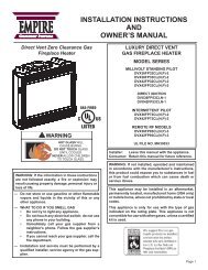
EMPIRE<br />
Comfort Systems<br />
Deluxe Vent-Free Universal Fireboxes<br />
INSTALLATION INSTRUCTIONS<br />
AND OwNER'S MANUAL<br />
GAS-FIRED<br />
ANSI Z21.91 Ventless Fireplace Enclosures for Gas Fired<br />
Decorative Type Unvented Room heaters<br />
wARNING: If the information in these instructions are not<br />
followed exactly, a fire or explosion may result causing<br />
property damage, personal injury or loss of life.<br />
— Do not store or use gasoline or other flammable vapors<br />
and liquids in the vicinity of this or any other appliance.<br />
— whAT TO DO IF yOU SMELL GAS<br />
• Do not try to light any appliance.<br />
• Do not touch any electrical switch; do not use any<br />
phone in your building.<br />
• Immediately call your gas supplier from a neighbor’s<br />
phone. Follow the gas supplier’s instructions.<br />
• If you cannot reach your gas supplier, call the fire<br />
department.<br />
— Installation and service must be performed by a qualified<br />
installer, service agency or the gas supplier.<br />
DO NOT ATTEMpT TO MODIFy OR ALTER ThE CONSTRUC-<br />
TION OF ThE FIREBOX OR ITS COMpONENTS. ANy MODI-<br />
FICATION OR ALTERATION OF CONSTRUCTION MAy VOID<br />
ThE wARRANTy OF ThIS FIREBOX.<br />
ChILDREN AND ADULTS ShOULD BE ALERTED TO ThE<br />
hAZARDS OF hIGh SURFACE TEMpERATURE AND<br />
ShOULD STAy AwAy TO AVOID BURNS OR CLOThING IG-<br />
NITION.<br />
yOUNG ChILDREN ShOULD BE CAREFULLy SUpERVISED<br />
whEN ThEy ARE IN ThE SAME ROOM AS ThE FIREBOX.<br />
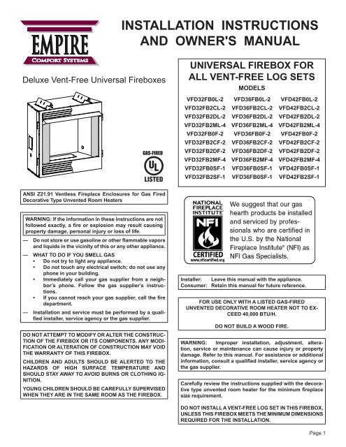
UNIVERSAL FIREBOX FOR<br />
ALL VENT-FREE LOG SETS<br />
MODELS<br />
<strong>VFD</strong><strong>32</strong>FB0L-2 <strong>VFD</strong><strong>36</strong>FB0L-2 <strong>VFD</strong><strong>42</strong>FB0L-2<br />
<strong>VFD</strong><strong>32</strong>FB2CL-2 <strong>VFD</strong><strong>36</strong>FB2CL-2 <strong>VFD</strong><strong>42</strong>FB2CL-2<br />
<strong>VFD</strong><strong>32</strong>FB2DL-2 <strong>VFD</strong><strong>36</strong>FB2DL-2 <strong>VFD</strong><strong>42</strong>FB2DL-2<br />
<strong>VFD</strong><strong>32</strong>FB2ML-4 <strong>VFD</strong><strong>36</strong>FB2ML-4 <strong>VFD</strong><strong>42</strong>FB2ML-4<br />
<strong>VFD</strong><strong>32</strong>FB0F-2 <strong>VFD</strong><strong>36</strong>FB0F-2 <strong>VFD</strong><strong>42</strong>FB0F-2<br />
<strong>VFD</strong><strong>32</strong>FB2CF-2 <strong>VFD</strong><strong>36</strong>FB2CF-2 <strong>VFD</strong><strong>42</strong>FB2CF-2<br />
<strong>VFD</strong><strong>32</strong>FB2DF-2 <strong>VFD</strong><strong>36</strong>FB2DF-2 <strong>VFD</strong><strong>42</strong>FB2DF-2<br />
<strong>VFD</strong><strong>32</strong>FB2MF-4 <strong>VFD</strong><strong>36</strong>FB2MF-4 <strong>VFD</strong><strong>42</strong>FB2MF-4<br />
<strong>VFD</strong><strong>32</strong>FB0SF-1 <strong>VFD</strong><strong>36</strong>FB0SF-1 <strong>VFD</strong><strong>42</strong>FB0SF-1<br />
<strong>VFD</strong><strong>32</strong>FB2SF-1 <strong>VFD</strong><strong>36</strong>FB0SF-1 <strong>VFD</strong><strong>42</strong>FB2SF-1<br />
Installer: Leave this manual with the appliance.<br />
Consumer: Retain this manual for future reference.<br />
FOR USE ONLy wITh A LISTED GAS-FIRED<br />
UNVENTED DECORATIVE ROOM hEATER NOT TO EX-<br />
CEED 40,000 BTU/h.<br />
DO NOT BUILD A wOOD FIRE.<br />
wARNING: Improper installation, adjustment, alteration,<br />
service or maintenance can cause injury or property<br />
damage. Refer to this manual. For assistance or additional<br />
information, consult a qualified installer, service agency or<br />
the gas supplier.<br />
Carefully review the instructions supplied with the decorative<br />
type unvented room heater for the minimum fireplace<br />
size requirement.<br />
DO NOT INSTALL A VENT-FREE LOG SET IN ThIS FIREBOX,<br />
UNLESS ThIS FIREBOX MEETS ThE MINIMUM DIMENSIONS<br />
REQUIRED FOR ThE INSTALLATION.<br />
Page 1
Page 2<br />
TABLE OF CONTENTS<br />
Section Page<br />
important Safety information ....................................................................................3<br />
clearances ............................................................................................................4-5<br />
Firebox installation instructions .............................................................................6-8<br />
installing Hood ......................................................................................................8-9<br />
gas Line connection ...............................................................................................9<br />
optional Fresh air Kit installation instructions ...................................................10-12<br />
optional Single Speed Blower installations instructions ...................................13-15<br />
Junction Box Wiring installation instructions ..........................................................16<br />
Maintenance ...........................................................................................................16<br />
Parts List .........................................................................................................17-19<br />
Parts View ..............................................................................................................20<br />
accessories .......................................................................................................21-22<br />
Master Parts Distributor List ...................................................................................23<br />
How to order Repair Parts ....................................................................................23<br />
Warranty .................................................................................................................24<br />
25476-5-0612
IMpORTANT SAFETy INFORMATION<br />
The installation must conform with local codes or, in<br />
the absence of local codes, with the National Fuel Gas<br />
Code, ANSI Z223.1 (latest edition) and to the National<br />
electrical Code, ANSI/NFpA70 (latest edition).<br />
NOTE: Installation and repair should be done by a qualified<br />
service person. The appliance should be inspected<br />
before use and at least annually by a qualified service<br />
person. More frequent cleaning may be required due<br />
to excessive lint from carpeting, bedding material, etc.<br />
It is imperative that control compartment, burners and<br />
circulating air passageways of the appliance be kept<br />
clean.<br />
This Empire Comfort Systems, Inc. firebox and its<br />
components have been tested and will operate safely<br />
when installed in accordance with this installation<br />
manual. Read all instructions before starting installation,<br />
then follow these instructions carefully during<br />
installation to maximize firebox benefit and safety.<br />
Report to your dealer any parts damaged in shipment.<br />
The Empire Comfort Systems, Inc. warranty will be<br />
voided by, and Empire Comfort Systems, Inc. disclaims<br />
any responsibility for the following actions:<br />
- Installation of any damaged firebox.<br />
- Modification of the firebox or any of the components<br />
parts thereof.<br />
- Installation other than as instructed by Empire<br />
Comfort Systems, Inc.<br />
Instructions to Installer<br />
1. installer must leave instruction manual with owner after<br />
installation.<br />
2. Installer must have owner fill out and mail warranty card<br />
supplied with firebox.<br />
3. installer should show owner how to start and operate<br />
log set that is installed into firebox.<br />
Important<br />
all correspondence should refer to complete Model number,<br />
Serial number.<br />
notice: During initial firing of this firebox with a log set<br />
installed, its paint will bake out, and smoke will occur. to<br />
prevent triggering of smoke alarms, ventilate the room in<br />
which the unit is installed.<br />
Qualified Installing Agency<br />
installation and replacement of gas piping, gas utilization<br />
equipment or accessories and repair and servicing of<br />
equipment shall be performed only by a qualified agency.<br />
The term "qualified agency" means any individual, firm,<br />
corporation or company which either in person or through<br />
a representative is engaged in and is responsible for (a)<br />
INTRODUCTION<br />
Any safety screen or guard removed for servicing an<br />
appliance must be replaced prior to operating the appliance.<br />
Provide adequate combustion and ventilation air.<br />
The flow of combustion and ventilation air MUST NOT<br />
be obstructed.<br />
provide adequate clearance around air openings into<br />
the combustion chamber and adequate accessibility<br />
clearance for servicing and proper operation. NEVER<br />
obstruct the front opening of the appliance.<br />
- Installation and/or use of any component part<br />
or accessory not approved by Empire Comfort<br />
Systems, Inc. in combination or assembly with<br />
a Empire Comfort Systems, Inc. firebox, not<br />
withstanding any independent testing laboratory<br />
or other third party approval of such component<br />
part or accessory.<br />
Any such action may create a possible fire hazard.<br />
Consult your local building codes.<br />
Firebox Screen.<br />
The firebox screen must be in place when the firebox<br />
is operating.<br />
the installation or replacement of gas piping or (b) the<br />
connection, installation, repair or servicing of equipment,<br />
who is experienced in such work, familiar with all precautions<br />
required and has complied with all the requirements of the<br />
authority having jurisdiction.<br />
State of Massachusetts: the installation must be made<br />
by a licensed plumber or gas fitter in the Commonwealth<br />
of Massachusetts. the state of Massachusetts requires<br />
that a flexible appliance connector cannot exceed three<br />
feet in length.<br />
Sellers of unvented propane or natural gas-fired<br />
supplemental room heaters shall provide to each<br />
purchaser a copy of 527 cMR 30 upon sale of the unit.<br />
in the State of Massachusetts, unvented propane and<br />
natural gas-fired space heaters shall be prohibited in<br />
bedrooms and bathrooms.<br />
the installation must conform with local codes or, in the<br />
absence of local codes, with the national Fuel gas code,<br />
anSi Z223.1/nFPa 54.*<br />
*available from the american national Standards institute,<br />
inc., 11 West <strong>42</strong>nd St., new York, n.Y. 100<strong>36</strong>.<br />
25476-5-0612 Page 3
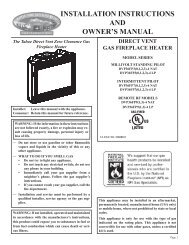
Sidewall Clearances: The clearance from the inside of the firebox<br />
to perpendicular combustible side wall should not be less than<br />
6". See Figure 1.<br />
Firebox Side and Back Clearances: The firebox outer casing side<br />
and back flanges are zero clearance to combustibles.<br />
Top Framing and Finishing: combustible framing may rest on<br />
top of standoffs. Combustible finishing materials may extend<br />
to the top standoff screws on the front edge of the outer wrap.<br />
See Figure 2.<br />
Page 4<br />
FRONT FACE (SIDE)<br />
FIREBOX<br />
(TOP VIEW)<br />
Figure 1<br />
3”<br />
MAX.<br />
45°<br />
6”<br />
PERPENDICULAR<br />
SIDE WALL<br />
CLEARANCES<br />
COMBUSTIBLE<br />
MATERIALS ALLOWED<br />
IN SHADED AREAS<br />
2 X 4<br />
HEADER<br />
2 X 4<br />
HEADER<br />
STAND OFF<br />
STAND OFF<br />
COMBUSTIBLE<br />
FINISHED WALL<br />
OR MANTEL<br />
Figure 2a - Louvered Models<br />
FINISHED WITH TRIM KIT OR<br />
NON-COMBUSTIBLE MATERIAL<br />
AS DESIRED.<br />
COMBUSTIBLE<br />
FINISHED WALL<br />
OR MANTEL<br />
Figure 2b - Flush Models<br />
FINISHED WITH TRIM KIT OR<br />
NON-COMBUSTIBLE MATERIAL<br />
AS DESIRED.<br />
25476-5-0612
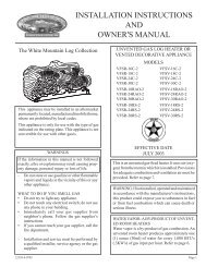
Ceiling Clearances: the ceiling height should not be less than <strong>42</strong>"<br />
from the top of the hood. See Figure 3.<br />
Mantel Clearances: Vent free firebox models must use the hood<br />
supplied with the firebox, or one of the optional hood kits available<br />
for each model. if a combustible mantel is installed, it must meet<br />
the clearance requirements detailed below.<br />
Grate Clearance: the minimum clearance between the front legs<br />
of the grate and front edge of the firebox is 2".<br />
Leave at least <strong>36</strong>" clearance from the front of the firebox.<br />
CEILING<br />
12”<br />
MAX<br />
10”<br />
21”<br />
<strong>42</strong>”<br />
MIN.<br />
(CEILING TO<br />
TOP OF HOOD)<br />
MANTEL<br />
10” 8”<br />
COMBUSTIBLES<br />
ALLOWED<br />
18 1/2”<br />
6 ½”<br />
16 1/2”<br />
5”<br />
13” 14 1/2”<br />
3 ½”<br />
84”<br />
12 1/2”<br />
2”<br />
MIN.<br />
(CEILING TO FLOOR)<br />
10 1/2”<br />
3/4”<br />
9”<br />
8”<br />
MIN.<br />
0”<br />
3/8” COMBUSTIBLE<br />
CLEARANCE REQUIRED<br />
FROM TOP T EDGE<br />
OF FIREBOX<br />
HOOD<br />
FIREBOX<br />
FACE<br />
Figure 3 - Clearances to Combustibles<br />
CLEARANCES<br />
25476-5-0612 Page 5
any vent-free gas Log Heater must be “For use with approved anSi<br />
Z21.11.2 unvented room heater.”<br />
Follow and complete the installation instructions of the gas log set<br />
and the requirements of this firebox.<br />
Check all fittings for leaks before lighting the gas log set.<br />
In planning the installation for the firebox, it is necessary to determine<br />
where the unit is to be installed and whether optional accessories<br />
are desired. gas supply piping should also be planned at this time.<br />
A gas shut off must be in this line.<br />
The firebox can be mounted on any of these surfaces:<br />
1. A flat hard combustible or non-combustible surface.<br />
2. a raised platform of combustible or non-combustible material.<br />
3. Recessed into the floor as illustrated by Figure 4 (flush face),<br />
and Figure 5 (louvered models).<br />
4. Supported under all (4) corners of the firebox so that contact<br />
is made on all four perimeter edges on the bottom of the unit<br />
(example: Four (4) concrete masonry blocks).<br />
If the firebox is installed directly on carpeting, tile or other combustible<br />
material other than wood flooring, it should be installed on a metal<br />
or wood panel extending the full width and depth of the unit.<br />
Page 6<br />
FLUSH FACE<br />
FIREBOX<br />
MODELS<br />
NON-COMBUSTIBLE<br />
FINISHING MATERIAL<br />
TO FIREBOX OPENING<br />
FIREBOX INSTALLATION INSTRUCTIONS<br />
COMBUSTIBLE MATERIALS ALLOWED<br />
Figure 4<br />
Deluxe Vent-Free Firebox Framing Dimensions (in inches)<br />
"a" "B" "c"<br />
Model Framing Height Framing Width Framing Depth<br />
<strong>VFD</strong><strong>32</strong>FB <strong>36</strong> 1/8" 35" 17"<br />
<strong>VFD</strong><strong>36</strong>FB 38 1/8" 40" 19 3/8"<br />
<strong>VFD</strong><strong>42</strong>FB 38 1/8" 44" 19 3/8"<br />
Attention: Add 3-3/4" to "A" Dimension when using flush mantel base.<br />
Framing dimension A includes a three inch clearance for standoffs on firebox.<br />
at this point, you should have decided what components to include<br />
in your installation, and where the firebox is to be located. If this<br />
has not been done, stop and consult your dealer for assistance<br />
with this planning.<br />
planning your Installation<br />
Please note that the optional VFa2 Fresh air kit available for use<br />
with the Vent Free Firebox must be installed at the time of the initial<br />
installation. Refer to pages 10, 11 and 12 for detailed instructions<br />
for the air kit.<br />
accessory kits such as the FBB5 Blower kit, trim kits, Mantles, Full<br />
cabinet Mantels, plus other Decorative Frame, Hood, and Door<br />
accessory kits may be installed after the firebox is secured to the<br />
framed opening.<br />
Refer to the instructions provided with each of the optional accessory<br />
kits for proper installation and operation.<br />
Firebox Framing<br />
Firebox framing can be built before or after the firebox is set in place.<br />
Framing should be positioned to accommodate wall covering and<br />
firebox facing material. The firebox framing should be constructed<br />
of 2 x 4 lumber or heavier. the framing headers may rest on the<br />
top of the firebox standoffs. Refer to Figures 6 and 7 for firebox<br />
framing dimensions.<br />
LOUVERED<br />
FIREBOX<br />
MODELS<br />
Figure 6<br />
COMBUSTIBLE MATERIALS ALLOWED<br />
Figure 5<br />
25476-5-0612
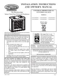
INDEX<br />
LETTER<br />
FIREBOX INSTALLATION INSTRUCTIONS (continued)<br />
J<br />
N<br />
K<br />
E<br />
OUTER FIREBOX DIMENSIONS (in inches)<br />
LOUVERED FLUSh<br />
<strong>VFD</strong><strong>32</strong> <strong>VFD</strong><strong>36</strong> <strong>VFD</strong><strong>42</strong> <strong>VFD</strong><strong>32</strong> <strong>VFD</strong><strong>36</strong> <strong>VFD</strong><strong>42</strong><br />
a 35 5/8 37 5/8 37 5/8 35 5/8 37 5/8 37 5/8<br />
B 34 1/2 39 1/2 43 1/2 34 1/2 39 1/2 43 1/2<br />
c 17 7/16 19 13/16 19 13/16 17 7/16 19 13/16 19 13/16<br />
D 29 33 37 29 33 37<br />
e 33 35 35 33 35 35<br />
F 31 <strong>36</strong> 40 31 <strong>36</strong> 40<br />
g 22 3/8 24 3/8 24 3/8 22 3/8 24 3/8 24 3/8<br />
H 1 1/4 1 1/4 1 1/4 6 1/8 6 1/8 6 1/8<br />
i 31 1/2 33 1/2 33 1/2 28 9/16 30 9/16 30 9/16<br />
J 8 3/8 8 3/8 8 3/8 8 3/8 8 3/8 8 3/8<br />
K 5 3/4 5 3/4 5 3/4 5 3/4 5 3/4 5 3/4<br />
L 31 13/16 <strong>36</strong> 3/16 38 3/16 31 13/16 <strong>36</strong> 3/16 38 3/16<br />
M 63 3/8 72 3/8 76 3/8 63 3/8 72 3/8 76 3/8<br />
n 2 11/16 2 11/16 2 11/16 2 11/16 2 11/16 2 11/16<br />
D<br />
DELUXE<br />
LOUVERED<br />
F<br />
B<br />
B<br />
TOP VIEW<br />
A<br />
OUTER FIREBOX DIMENSIONS<br />
G I A<br />
H<br />
INNER FIREBOX DIMENSIONS<br />
Figure 7<br />
Firebox Dimensions<br />
25476-5-0612 Page 7<br />
E<br />
E<br />
DELUXE<br />
FLUSH<br />
M<br />
F<br />
B<br />
SIDE VIEW<br />
C<br />
G I A<br />
H<br />
D<br />
L<br />
C<br />
K<br />
J<br />
N<br />
INNER FIREBOX DIMENSIONS (in inches)<br />
INDEX<br />
LETTER<br />
<strong>VFD</strong><strong>32</strong> <strong>VFD</strong><strong>36</strong> <strong>VFD</strong><strong>42</strong><br />
wIThOUT BRICK<br />
a 30 7/8 35 7/8 39 7/8<br />
B 24 15/16 28 15/16 <strong>32</strong> 15/16<br />
c 14 3/16 16 9/16 16 9/16<br />
D 18 3/8 19 3/4 19 3/4<br />
e 21 9/16 23 9/16 23 9/16<br />
wITh BRICK<br />
a 29 1/8 34 1/8 38 1/8<br />
B 23 5/8 27 5/8 31 5/8<br />
c 12 7/8 15 5/16 15 5/16<br />
D 18 3/8 19 3/4 19 3/4<br />
e 21 9/16 23 9/16 23 9/16
Locating Firebox<br />
Place firebox in framing opening. Use the four (4) framing brackets<br />
provided on the firebox to attach firebox to framing. Different hole<br />
locations can be used for finishing materials with thicknesses of<br />
3/8", 1/2" and 3/4". attach these materials with screws provided,<br />
two (2) per framing bracket. See Figure 8.<br />
Framing brackets should fit directly against framing material. Use<br />
at least one (1) nail per bracket to secure in place.<br />
Check squareness of the firebox prior to securing to framed opening.<br />
See Figure 9.<br />
Page 8<br />
Figure 8<br />
A black hood that is furnished with each firebox (or optional hood)<br />
MUST be installed before the firebox is used. Failure to do so<br />
may create a possible fire hazard. The hood is located behind<br />
upper louver, or inside the firebox on flush face units. If brass,<br />
stainless steel, or hammered pewter hoods are desired, they can<br />
be purchased as an option. attachment is the same as the standard<br />
black hood.<br />
Flush Face Models<br />
1. On flush face models, loosen the two screws (A) holding firebox<br />
top to face panel, then slide the hood flange between the firebox<br />
top and face panel and re-tighten the screws.<br />
2. install one (1) screw at each end of the hood as shown (c).<br />
Louvered Models<br />
FIREBOX INSTALLATION INSTRUCTIONS (continued)<br />
ATTACH (4)<br />
FRAMING BRACKETS<br />
TO SIDES OF FIREBOX<br />
PRIOR TO INSTALLING<br />
UNIT TO FRAMED OPENING<br />
1. if you have a louvered model, remove upper louver.<br />
2. Place the top hood flange on top of the firebox, then install three<br />
screws through the firebox top from below and screw into the<br />
pilot holes in the hood flange (B).<br />
3. install one (1) screw at each end of the hood as shown (c).<br />
4. Re-install louver.<br />
Caution: the hood must be installed prior to operation of appliance.<br />
See Figure 10<br />
INSTALLING hOOD<br />
B<br />
FIREBOX OPENING<br />
CHECK TO SEE<br />
THAT BOX IS SQUARE<br />
PRIOR TO ATTACHING TO<br />
FRAMING<br />
A<br />
Figure 9<br />
Flush Face Models<br />
C<br />
Figure 10<br />
C<br />
A<br />
C<br />
INNER FIREBOX TOP<br />
Louvered Models<br />
25476-5-0612
Extended hoods<br />
If your non-combustible facing material is over 1" in thickness that will be used to finish this firebox, an extended hood is available that will<br />
extend out 2" farther out into the room. contact your local dealer for details.<br />
VB4H<strong>32</strong>BL Standard Black VB4H<strong>36</strong>BL Standard Black VB4H<strong>42</strong>BL Standard Black<br />
VB4H<strong>32</strong>BR Polished Brass VB4H<strong>36</strong>BR Polished Brass VB4H<strong>42</strong>BR Polished Brass<br />
VB4H<strong>32</strong>SS Stainless Steel VB4H<strong>36</strong>SS Stainless Steel VB4H<strong>42</strong>SS Stainless Steel<br />
VB4H<strong>32</strong>HP Hammered Pewter VB4H<strong>36</strong>HP Hammered Pewter VB4H<strong>42</strong>HP Hammered Pewter<br />
Finishing<br />
All joints (top, bottom and sides), where the wall or decorative facing material meets the firebox surround should be sealed with a noncombustible<br />
material.<br />
<strong>Hearth</strong> extensions are recommended, but not required for these fireboxes.<br />
The firebox is designed to accept a 3/8-inch gas line for an approved<br />
vent-free gas logset. Have the line installed by a qualified service<br />
person in accordance with all building codes. consult local building<br />
codes to properly size the gas supply line leading to the 3/8-inch<br />
hook-up at the unit. the state of Massachusetts requires that a<br />
flexible appliance connector cannot exceed three feet in length.<br />
Gas access holes are provided on both sides of the firebox. See<br />
Figure 11. on models with refractory brick panels installed,<br />
carefully remove the knockout in the refractory brick panel using a<br />
large standard screwdriver and hammer. First, place screwdriver in<br />
groove next to plug and pry sideways to pop out main plug. then<br />
remove the remaining concrete in hole with gentle tapping with ball<br />
peen hammer and/or screwdriver. a masonry drill and bit may also<br />
be used to create a clean hole for the gas line to pass through.<br />
See Figure 12.<br />
When installing optional ceramic fiber side panels into firebox,<br />
lay panel on a flat surface. Remove the gas line knockout (round<br />
depression) in the appropriate side panel using a drill or utility knife.<br />
When installing decorative stainless steel or reflective black<br />
liners, gas access holes in the bottom of the firebox are required.<br />
If no access holes are available in the bottom of the firebox,<br />
see installation instructions for decorative liners for proper hole<br />
placement.<br />
After the brick panel knockout is removed, the firebox wrap may<br />
have a round metal knockout that must be removed also. Use a<br />
screwdriver to punch out the metal knockout.<br />
check gas type. Use only the gas type indicated on the gas log<br />
set rating plate. if the gas listed on the plate is not your type of gas<br />
supply, Do not inStaLL. contact your dealer for proper model.<br />
Always use an external regulator for all LP fireboxes to reduce the<br />
supply tank pressure to a maximum of 14" w.c. this is in addition<br />
to the regulator fitted to the log set.<br />
WaRning: connection DiRectLY to an UnRegULateD<br />
L.P. tanK can caUSe eXPLoSion.<br />
Install only a ANSI Z21.11.2 vent-free log set into this firebox.<br />
INSTALLING hOOD (continued)<br />
GAS LINE CONNECTION<br />
Ceramic Fiber Panel<br />
GAS ACCESS HOLES<br />
Figure 11<br />
Figure 12<br />
Refractory Brick Panel<br />
25476-5-0612 Page 9
Page 10<br />
OpTIONAL FRESh AIR KIT INSTALLATION INSTRUCTIONS<br />
FOR DELUXE AND pREMIUM FIREBOXES<br />
the optional Fresh air Kit is designed to introduce outside air to<br />
the firebox as desired.<br />
It must be installed prior to, or at the time of firebox installation to<br />
framing.<br />
the Fresh air kit must be installed prior to the installation of wallboard<br />
or other finishing materials around the unit.<br />
hardware needed (not provided): 4” aluminum Flex Duct,<br />
2 Band clamps<br />
Tools needed: gloves, Metal snips, 5/16” nut Driver,<br />
Phillips Screwdriver<br />
Caution: Sharp edges<br />
Slide assembly installation<br />
1. Begin by removing the rectangular cutout located on the left<br />
side of the unit. Use gloves and sheet metal snips to create<br />
the opening for the air Door assembly to install into. See Figure<br />
13.<br />
Figure 13<br />
2. Remove the cover plate on the left side of the firebox and discard.<br />
See Figure 14a. Some units will not have a cover plate.<br />
For those units, bend the tab out of the way. See Figure 14b.<br />
Figure 14a<br />
Figure 14b<br />
3. insert Slide assembly through the cut-out as shown in Figure<br />
15. Before you fasten ensure that the handle penetrates the<br />
inner firebox wall. See Figure 16. Fasten the Slide Assembly<br />
with the four 10 x 1/2 Hex Head Screws provided.<br />
Figure 15<br />
4. Fasten the Handle<br />
Figure 16<br />
Retainer to the firebox side with<br />
two 10 x 1/2 Phillips truss Head Screws as shown in Figure<br />
16.<br />
25476-5-0612
OpTIONAL FRESh AIR KIT INSTALLATION INSTRUCTIONS<br />
FOR DELUXE AND pREMIUM FIREBOXES<br />
5. Push the handle for “open” position and pull the handle for<br />
the “closed” position. See Figure 17.<br />
CLOSED<br />
OPEN<br />
Figure 17<br />
Completion of Air Kit installation<br />
1. Determine the length of 4” Dia. rigid or flex duct connector<br />
(installer supplied) you will need from the firebox/fireplace to<br />
the exterior surface of the outside wall, where the air kit hood<br />
will be installed. add a few extra inches to the length to allow<br />
for easier attachment of the outside duct connection prior to<br />
securing the outside rain cap hood to the building.<br />
2. Secure the 4” dia. duct to the Slide assembly collar on the<br />
firebox with band clamps or screws (installer supplied).<br />
3. Run the other end of the duct through the exterior wall cutout.<br />
4. From the outside of the building, connect the duct to the collar<br />
on the outside air vent assembly with band clamp or screws<br />
to secure (installer supplied).<br />
5. Secure the outside air Vent assembly to the outside wall with<br />
the four 10 x 1 1/2 Hex Head Slotted Screws provided. Seal<br />
with caulk as necessary. See Figure 18.<br />
6. Figure 19 illustrates the various options for installation of the<br />
air duct run possibilities.<br />
Note: In installations where the flex duct would normally be<br />
straight (without turns), it is recommended a turn or dip<br />
be added in the run to reduce air velocity.<br />
CAULKING<br />
caulk and install Duct termination<br />
Figure 18<br />
Figure 19<br />
OUTSIDE<br />
AIR VENT ASSY<br />
25476-5-0612 Page 11<br />
WALL
Page 12<br />
OpTIONAL FRESh AIR KIT INSTALLATION INSTRUCTIONS<br />
FOR DELUXE AND pREMIUM FIREBOXES<br />
3<br />
1<br />
pARTS LIST<br />
INDEX NO. pART NO. DESCRIpTION<br />
1 29259 outside air Vent assembly<br />
2 29257 Slide assembly<br />
3 29263 Handle Retainer<br />
Hardware Pack<br />
R-3580, PHILLIPS TRUSS HEAD SCREW 10 X ½ - QTY - 2<br />
R-2737, HEX HEAD SCREW 10 X ½ BLACK - QTY - 4<br />
R-1134, HEX HEAD SLOTTED SCREW 10 X 1½ - QTY - 4<br />
2<br />
25476-5-0612
OpTIONAL SINGLE SpEED BLOwER INSTALLATION INSTRUCTIONS<br />
Attention: install blower assembly before connecting gas inlet<br />
supply line.<br />
wiring<br />
the appliance, when installed, must be electrically grounded in<br />
accordance with local codes or, in the absence of local codes,<br />
with the National Electrical Code, ANSI/NFPA 70, if an external<br />
electrical source is utilized. This appliance is equipped with<br />
a three-prong [grounding] plug for your protection against<br />
shock hazard and should be plugged directly into a properly<br />
grounded three-prong receptacle. Do not cut or remove the<br />
grounding prong from this plug. For an ungrounded receptacle,<br />
an adapter, which has two prongs and a wire for grounding, can be<br />
purchased, plugged into the ungrounded receptacle and its wire<br />
connected to the receptacle mounting screw. With this wire completing<br />
the ground, the appliance cord plug can be plugged into the<br />
adapter and be electrically grounded.<br />
Caution: Label all wires prior to disconnection when servicing<br />
controls. Wiring errors can cause improper and dangerous<br />
operation. Verify proper operation after servicing.<br />
Note: Junction box on right side of firebox must be pre-wired at<br />
time of firebox installation for use with blower assembly. A<br />
standard wall on/oFF wall switch or optional ScV1 Variable<br />
Speed control Kit should be installed to activate power<br />
to the Firebox, and control the operation of the FBB5<br />
Blower assembly. it is recommended that installation of the<br />
wiring be performed by a qualified electrician. See Figure<br />
20.<br />
1. If installed, turn OFF gas supply to firebox/gas log.<br />
2. If applicable, turn OFF electric supply to firebox.<br />
CAUTION: aLL WiRing SHoULD Be Done BY a QUaLi-<br />
FieD eLectRician anD SHaLL Be in coMPLiance WitH<br />
aLL LocaL, citY anD State BUiLDing coDeS. BeFoRe<br />
MaKing tHe eLectRicaL connection, MaKe SURe<br />
tHat Main PoWeR SUPPLY iS DiSconnecteD. tHe<br />
aPPLiance, WHen inStaLLeD, MUSt Be eLectRicaL-<br />
LY gRoUnDeD in accoRDance WitH LocaL coDeS,<br />
WitH tHe nationaL eLectRicaL coDe anSi/nFPa 70<br />
(LateSt eDition).<br />
Figure 20<br />
a factory installed junction box is located on the lower right<br />
side of the firebox. Wiring must be fed to the junction box and<br />
attached to the receptacle that is provided. From right side of<br />
the firebox, remove the screw securing the junction box assembly.<br />
Leave approximately 6” of wire in the junction box for<br />
connection.<br />
attach black wire to one side of the receptacle and white wire<br />
to opposite side of receptacle. the ground wire should be attached<br />
to the green (ground) screw.<br />
install the receptacle into the junction box. attach cover plate.<br />
Attention: if installed, do not damage gas inlet supply line<br />
when blower assembly is inserted into firebox. In some cases,<br />
removal the gas inlet supply line may be necessary.<br />
3. Determine which type of firebox you have prior to installation.<br />
See Figures 21 and 22.<br />
Figure 21<br />
Figure 22<br />
Deluxe Louvered<br />
Models<br />
REMOVE BOTTOM LOUVER TO<br />
INSTALL BLOWER ASSEMBLY<br />
Deluxe Flush Face<br />
Models<br />
REMOVE COVER PLATE TO<br />
INSTALL BLOWER ASSEMBLY<br />
25476-5-0612 Page 13
OpTIONAL SINGLE SpEED BLOwER INSTALLATION INSTRUCTIONS<br />
4. Insert blower assembly into interior, bottom of firebox. Position<br />
blower assembly so that you align the notch on back of<br />
blower assembly with the center screw on firebox back, then<br />
push the blower assembly against firebox back. The blower<br />
wheel must be centered with the back wall of the firebox. The<br />
magnets on the back and bottom of blower assembly will sufficiently<br />
hold blower assembly in place.<br />
5. once the blower assembly is in position, locate the plug button<br />
in the top right rear corner of the firebox. Remove the plug<br />
with a standard screwdriver and discard plug.<br />
6. Next, find the fan control switch and wire assembly. Feed the<br />
wires through the hole at the top of the firebox, and secure the<br />
fan control switch with (2) #6 screws provided. See Figure 23.<br />
7. The fan control wires will slide down between the firebox and<br />
outer wrap near the blower assembly. See Figure 28.<br />
Page 14<br />
FAN CONTROL<br />
SWITCH LOCATION<br />
FAN CONTROL WIRES<br />
Figure 23<br />
8. one fan control wire will have a 1/4” female terminal that must<br />
be attached to the open terminal on the blower motor. See<br />
Figure 26, Connection A.<br />
9. the other fan control wire has a 1/4” male terminal. attach this<br />
terminal to the open terminal on the blower power cord. See<br />
Figure 26, Connection B<br />
10. Route the wires away from moving parts of the blower assembly<br />
and retain wires together near the blower motor using the<br />
plastic purse clip provided.<br />
11. to complete the installation, plug the power cord into the junction<br />
box receptacle at the right rear corner of the firebox outer<br />
wrap. See Figure 24.<br />
12. if room permits, the power cord can be located from the outside<br />
of the unit looking through the junction box access hole<br />
(with the junction box removed), then plug up the power cord<br />
before reinstalling the pre-wired junction box.<br />
13. once all connections are made electrically, it is recommended<br />
that you test the blower fan control operation by turning on<br />
power to the blower (caution: 110 Volt). then apply heat to<br />
the fan control switch inside the firebox with a lighter or match<br />
until blower is activated. once blower is activated, check for<br />
proper operation. Do not place hands near blower assembly<br />
or other wiring while power is on.<br />
14. Replace blower access plate and/or reinstall the brick liner<br />
panels if provided.<br />
15. this completes the installation of the optional FBB5 Blower kit<br />
accessory.<br />
Note: this blower is equipped with a heat activated fan control<br />
switch. Blower will operate when the firebox warms up, and<br />
will turn off automatically when the firebox cools down.<br />
BLOWER POWER CORD<br />
Figure 24<br />
25476-5-0612
OpTIONAL SINGLE SpEED BLOwER INSTALLATION INSTRUCTIONS<br />
Blower Motor<br />
the blower motor does not have oiling holes. Do not attempt to oil<br />
the blower motor.<br />
Blower wheels<br />
the blower wheels will collect lint and could require periodic cleaning.<br />
if the air output decreases or the noise level increases, it indicates<br />
a dirty blower wheel. Remove fan and clean blower wheels.<br />
warning: Unplugging of blower accessory will not stop the<br />
heater from cycling. to turn off gas to the heater (millivolt<br />
model): push in gas control knob slightly and turn clockwise<br />
to “oFF.” Do not force. to turn off gas on direct ignition model,<br />
turn gas line valve to “oFF.”<br />
1 R7731 BLoWeR aSSeMBLY<br />
2 R8199 Fan contRoL SWitcH<br />
Figure 26<br />
FAN/MOTOR<br />
ASSEMBLY<br />
FAN<br />
SWITCH<br />
25476-5-0612 Page 15<br />
1<br />
B<br />
A<br />
WHITE<br />
JUNCTION BOX<br />
BLACK<br />
Figure 25<br />
2<br />
110 VOLT AC
CAUTION: ALL wIRING ShOULD BE DONE By A QUALIFIED ELECTRICIAN AND ShALL BE IN COMpLIANCE wITh ALL LOCAL,<br />
CITy AND STATE BUILDING CODES. BEFORE MAKING ThE ELECTRICAL CONNECTION, MAKE SURE ThAT MAIN pOwER SUppLy<br />
IS DISCONNECTED. ThE AppLIANCE, whEN INSTALLED, MUST BE ELECTRICALLy GROUNDED IN ACCORDANCE wITh LOCAL<br />
CODES OR, IN ThE ABSENCE OF LOCAL CODES, wITh ThE NATIONAL ELECTRICAL CODE ANSI/NFpA 70 (LATEST EDITION)<br />
a factory installed junction box is located on the lower right hand<br />
side of the firebox. Wiring must be fed to the junction box and<br />
attached to the receptacle that is provided. Remove the knockout<br />
in the installed junction box to accept wiring into the junction box.<br />
install a UL listed cable clamp (not supplied) in the knockout hole.<br />
Leave approximately 6" of wire in the junction box for connection.<br />
attach black wire to one side of the receptacle and white wire to<br />
opposite side of receptacle. the ground wire should be attached<br />
to the green (neutral) screw.<br />
install the receptacle into the junction box. attach cover plate.<br />
Keep the control compartment, logs and burner area surrounding<br />
the logs clean by vacuuming or brushing area at least twice a year.<br />
tHe LogS can get VeRY Hot – HanDLe onLY WHen cooL.<br />
always turn off gas to the pilot before cleaning. For relighting, refer<br />
to lighting instructions located on the log set.<br />
Page 16<br />
JUNCTION BOX wIRING INSTALLATION INSTRUCTIONS<br />
MAINTENANCE<br />
Figure 27<br />
Never obstruct the flow of the combustion and ventilation air. Keep<br />
the front of the firebox clear of all obstacles and materials.<br />
Screens must be closed during operation.<br />
25476-5-0612
index<br />
no.<br />
Part no. Description<br />
<strong>VFD</strong><strong>32</strong>FB(0L,CL,DL,ML,0F,CF,DF,MF)<br />
1 17149 top Standoff (Qty 2)<br />
2 17169 Upper Louver<br />
3 10554 Framing Bracket (Qty 4)<br />
4 17170 Lower Louver<br />
5 17162 Junction Box assembly<br />
6 R3492 Receptacle<br />
7 R3491 cover, Junction Box<br />
8 216<strong>42</strong><br />
8 27338<br />
Bracket, top Brick Retainer (aged Brick<br />
Models) (Qty 2)<br />
Bracket, top Brick Retainer (Refractory &<br />
traditional Models) (Qty 2)<br />
9 19401 Bracket, Bottom Brick Retainer (Qty 2)<br />
10 R8220<br />
Brick Panel Right aged Brick Fiber -<br />
<strong>VFD</strong><strong>32</strong>FB2c<br />
10 R10388<br />
Brick Panel Right Refractory Brick -<br />
<strong>VFD</strong><strong>32</strong>FB2M<br />
11 R8221<br />
Brick Panel Back aged Brick Fiber -<br />
<strong>VFD</strong><strong>32</strong>FB2c<br />
11 R10386<br />
Brick Panel Back Refractory Brick -<br />
<strong>VFD</strong><strong>32</strong>FB2M<br />
11 R8676<br />
Brick Panel Back traditional Fiber -<br />
<strong>VFD</strong><strong>32</strong>FB2D<br />
11 R8675<br />
Brick Panel Right traditional Fiber -<br />
<strong>VFD</strong><strong>32</strong>FB2D<br />
12 R8219<br />
Brick Panel Left aged Brick Fiber -<br />
<strong>VFD</strong><strong>32</strong>FB2c<br />
12 R10387<br />
Brick Panel Left Refractory Brick -<br />
<strong>VFD</strong><strong>32</strong>FB2M<br />
12 R8674<br />
Brick Panel Left traditional Fiber -<br />
<strong>VFD</strong><strong>32</strong>FB2D<br />
13 20486 Hood<br />
14 R7051 Rod, Screen (Qty 2)<br />
15 R8137 Screen curtain (Qty 2)<br />
16 R8727 Hole Plug<br />
17 25477 Blower cover Plate<br />
18 25490 Front Panel - Flush<br />
18 26444 Front Panel - Louvered<br />
pARTS LIST<br />
index<br />
no.<br />
Part no. Description<br />
<strong>VFD</strong><strong>32</strong>FB(0,2)SF<br />
1 17149 top Standoff (Qty 2)<br />
3 10554 Framing Bracket (Qty 4)<br />
5 17162 Junction Box assembly<br />
6 R3492 Receptacle<br />
7 R3491 cover, Junction Box<br />
8 216<strong>42</strong><br />
Bracket, top Brick Retainer (aged Brick<br />
Models) (Qty 2)<br />
8 27338<br />
Bracket, top Brick Retainer (Refractory &<br />
traditional Models) (Qty 2)<br />
9 19401 Bracket, Bottom Brick Retainer (Qty 2)<br />
10 R8220<br />
Brick Panel Right aged Brick Fiber -<br />
<strong>VFD</strong><strong>32</strong>FB2c<br />
10 R10388<br />
Brick Panel Right Refractory Brick -<br />
<strong>VFD</strong><strong>32</strong>FB2M<br />
11 R8221<br />
Brick Panel Back aged Brick Fiber -<br />
<strong>VFD</strong><strong>32</strong>FB2c<br />
11 R10386<br />
Brick Panel Back Refractory Brick -<br />
<strong>VFD</strong><strong>32</strong>FB2M<br />
11 R8676<br />
Brick Panel Back traditional Fiber -<br />
<strong>VFD</strong><strong>32</strong>FB2D<br />
11 R8675<br />
Brick Panel Right traditional Fiber -<br />
<strong>VFD</strong><strong>32</strong>FB2D<br />
12 R8219<br />
Brick Panel Left aged Brick Fiber -<br />
<strong>VFD</strong><strong>32</strong>FB2c<br />
12 R10387<br />
Brick Panel Left Refractory Brick -<br />
<strong>VFD</strong><strong>32</strong>FB2M<br />
12 R8674<br />
Brick Panel Left traditional Fiber -<br />
<strong>VFD</strong><strong>32</strong>FB2D<br />
13 21117 Hood<br />
14 R11107 Rod, Screen (Qty 2)<br />
15 R11108 Screen curtain (Qty 2)<br />
16 R8727 Hole Plug<br />
17 29067 Blower cover Plate<br />
18 28987 Front Panel - Flush<br />
25476-5-0612 Page 17
index<br />
no.<br />
Page 18<br />
Part no. Description<br />
<strong>VFD</strong><strong>36</strong>FB(0L,CL,DL,ML,0F,CF,DF,MF)<br />
1 17247 top Standoff (Qty 2)<br />
2 18807 Upper Louver<br />
3 10554 Framing Bracket (Qty 4)<br />
4 18808 Lower Louver<br />
5 17162 Junction Box assembly<br />
6 R3492 Receptacle<br />
7 R3491 cover, Junction Box<br />
8 216<strong>42</strong><br />
8 27338<br />
Bracket, top Brick Retainer (aged Brick<br />
Models) (Qty 2)<br />
Bracket, top Brick Retainer (Refractory &<br />
traditional Models) (Qty 2)<br />
9 19401 Bracket, Bottom Brick Retainer (Qty 2)<br />
10 R8783<br />
Brick Panel Right aged Brick Fiber -<br />
<strong>VFD</strong><strong>36</strong>FB2c<br />
10 R10392<br />
Brick Panel Right Refractory Brick -<br />
<strong>VFD</strong><strong>36</strong>FB2M<br />
11 R8278<br />
Brick Panel Back aged Brick Fiber -<br />
<strong>VFD</strong><strong>36</strong>FB2c<br />
11 R10390<br />
Brick Panel Back Refractory Brick -<br />
<strong>VFD</strong><strong>36</strong>FB2M<br />
11 R8679<br />
Brick Panel Back traditional Fiber -<br />
<strong>VFD</strong><strong>36</strong>FB2D<br />
11 R8678<br />
Brick Panel Right traditional Fiber -<br />
<strong>VFD</strong><strong>36</strong>FB2D<br />
12 R8782<br />
Brick Panel Left aged Brick Fiber -<br />
<strong>VFD</strong><strong>36</strong>FB2c<br />
12 R10391<br />
Brick Panel Left Refractory Brick -<br />
<strong>VFD</strong><strong>36</strong>FB2M<br />
12 R8677<br />
Brick Panel Left traditional Fiber -<br />
<strong>VFD</strong><strong>36</strong>FB2D<br />
13 21087 Hood<br />
14 R7052 Rod, Screen (Qty 2)<br />
15* R8148 Screen curtain (Qty 2)<br />
16 R8727 Hole Plug<br />
17 25477 Blower cover Plate<br />
18 26678 Front Panel - Flush<br />
18 26679 Front Panel - Louvered<br />
* Stainless steel screen curtain may discolor over time.<br />
pARTS LIST<br />
index<br />
no.<br />
Part no. Description<br />
<strong>VFD</strong><strong>36</strong>FB(0,2)SF<br />
1 17247 top Standoff (Qty 2)<br />
3 10554 Framing Bracket (Qty 4)<br />
5 17162 Junction Box assembly<br />
6 R3492 Receptacle<br />
7 R3491 cover, Junction Box<br />
8 216<strong>42</strong><br />
Bracket, top Brick Retainer (aged Brick<br />
Models) (Qty 2)<br />
8 27338<br />
Bracket, top Brick Retainer (Refractory &<br />
traditional Models) (Qty 2)<br />
9 19401 Bracket, Bottom Brick Retainer (Qty 2)<br />
10 R8783<br />
Brick Panel Right aged Brick Fiber -<br />
<strong>VFD</strong><strong>36</strong>FB2c<br />
10 R10392<br />
Brick Panel Right Refractory Brick -<br />
<strong>VFD</strong><strong>36</strong>FB2M<br />
11 R8278<br />
Brick Panel Back aged Brick Fiber -<br />
<strong>VFD</strong><strong>36</strong>FB2c<br />
11 R10390<br />
Brick Panel Back Refractory Brick -<br />
<strong>VFD</strong><strong>36</strong>FB2M<br />
11 R8679<br />
Brick Panel Back traditional Fiber -<br />
<strong>VFD</strong><strong>36</strong>FB2D<br />
11 R8678<br />
Brick Panel Right traditional Fiber -<br />
<strong>VFD</strong><strong>36</strong>FB2D<br />
12 R8782<br />
Brick Panel Left aged Brick Fiber -<br />
<strong>VFD</strong><strong>36</strong>FB2c<br />
12 R10391<br />
Brick Panel Left Refractory Brick -<br />
<strong>VFD</strong><strong>36</strong>FB2M<br />
12 R8677<br />
Brick Panel Left traditional Fiber -<br />
<strong>VFD</strong><strong>36</strong>FB2D<br />
13 21162 Hood<br />
14 R110<strong>36</strong> Rod, Screen (Qty 2)<br />
15 R10765 Screen curtain (Qty 2)<br />
16 R8727 Hole Plug<br />
17 29067 Blower cover Plate<br />
18 27781 Front Panel - Flush<br />
25476-5-0612
index<br />
no.<br />
Part no. Description<br />
<strong>VFD</strong><strong>42</strong>FB(0L,CL,DL,ML,0F,CF,DF,MF)<br />
1 17247 top Standoff (Qty 2)<br />
2 17187 Upper Louver<br />
3 10554 Framing Bracket (Qty 4)<br />
4 17188 Lower Louver<br />
5 17162 Junction Box assembly<br />
6 R3492 Receptacle<br />
7 R3491 cover, Junction Box<br />
8 216<strong>42</strong><br />
8 27338<br />
Bracket, top Brick Retainer (aged Brick<br />
Models) (Qty 2)<br />
Bracket, top Brick Retainer (Refractory &<br />
traditional Models) (Qty 2)<br />
9 19401 Bracket, Bottom Brick Retainer (Qty 2)<br />
10 R8267<br />
Brick Panel Right aged Brick Fiber -<br />
<strong>VFD</strong><strong>42</strong>FB2c<br />
10 R10392<br />
Brick Panel Right Refractory Brick -<br />
<strong>VFD</strong><strong>42</strong>FB2M<br />
11 R8284<br />
Brick Panel Back aged Brick Fiber -<br />
<strong>VFD</strong><strong>42</strong>FB2c<br />
11 R10394<br />
Brick Panel Back Refractory Brick -<br />
<strong>VFD</strong><strong>42</strong>FB2M<br />
11 R8680<br />
Brick Panel Back traditional Fiber -<br />
<strong>VFD</strong><strong>42</strong>FB2D<br />
11 R8691<br />
Brick Panel Right traditional Fiber -<br />
<strong>VFD</strong><strong>42</strong>FB2D<br />
12 R8277<br />
Brick Panel Left aged Brick Fiber -<br />
<strong>VFD</strong><strong>42</strong>FB2c<br />
12 R10391<br />
Brick Panel Left Refractory Brick -<br />
<strong>VFD</strong><strong>42</strong>FB2M<br />
12 R8690<br />
Brick Panel Left traditional Fiber -<br />
<strong>VFD</strong><strong>42</strong>FB2D<br />
13 19984 Hood<br />
14 R7053 Rod, Screen (Qty 2)<br />
15* R8148 Screen curtain (Qty 2)<br />
16 R8727 Hole Plug<br />
17 25477 Blower cover Plate<br />
18 26689 Front Panel - Flush<br />
18 26690 Front Panel - Louvered<br />
* Stainless steel screen curtain may discolor over time.<br />
pARTS LIST<br />
index<br />
no.<br />
Part no. Description<br />
<strong>VFD</strong><strong>42</strong>FB(0,2)SF<br />
1 17247 top Standoff (Qty 2)<br />
3 10554 Framing Bracket (Qty 4)<br />
5 17162 Junction Box assembly<br />
6 R3492 Receptacle<br />
7 R3491 cover, Junction Box<br />
8 216<strong>42</strong><br />
Bracket, top Brick Retainer (aged Brick<br />
Models) (Qty 2)<br />
8 27338<br />
Bracket, top Brick Retainer (Refractory &<br />
traditional Models) (Qty 2)<br />
9 19401 Bracket, Bottom Brick Retainer (Qty 2)<br />
10 R8267<br />
Brick Panel Right aged Brick Fiber -<br />
<strong>VFD</strong><strong>42</strong>FB2c<br />
10 R10392<br />
Brick Panel Right Refractory Brick -<br />
<strong>VFD</strong><strong>42</strong>FB2M<br />
11 R8284<br />
Brick Panel Back aged Brick Fiber -<br />
<strong>VFD</strong><strong>42</strong>FB2c<br />
11 R10394<br />
Brick Panel Back Refractory Brick -<br />
<strong>VFD</strong><strong>42</strong>FB2M<br />
11 R8680<br />
Brick Panel Back traditional Fiber -<br />
<strong>VFD</strong><strong>42</strong>FB2D<br />
11 R8691<br />
Brick Panel Right traditional Fiber -<br />
<strong>VFD</strong><strong>42</strong>FB2D<br />
12 R8277<br />
Brick Panel Left aged Brick Fiber -<br />
<strong>VFD</strong><strong>42</strong>FB2c<br />
12 R10391<br />
Brick Panel Left Refractory Brick -<br />
<strong>VFD</strong><strong>42</strong>FB2M<br />
12 R8690<br />
Brick Panel Left traditional Fiber -<br />
<strong>VFD</strong><strong>42</strong>FB2D<br />
13 20237 Hood<br />
14 R11037 Rod, Screen (Qty 2)<br />
15 R10766 Screen curtain (Qty 2)<br />
16 R8727 Hole Plug<br />
17 29067 Blower cover Plate<br />
18 27782 Front Panel - Flush<br />
25476-5-0612 Page 19
Page 20<br />
16<br />
12<br />
1<br />
pARTS VIEw<br />
11<br />
18<br />
10<br />
3<br />
17<br />
7<br />
6<br />
14<br />
5<br />
8<br />
2<br />
4<br />
14<br />
18<br />
9<br />
15<br />
13<br />
25476-5-0612
Accessory Description Model Numbers<br />
Fan Kit<br />
Variable Speed Control Kit<br />
Brick Liners<br />
Fresh Air Kit<br />
1<br />
3<br />
Frame Kits<br />
2<br />
1<br />
2<br />
Designed to provide forced air flow. FBB5<br />
Wall mounted variable speed control for use<br />
with FBB5 blower<br />
Deluxe Firebox<br />
Standard Hood Brass hood = BR<br />
ACCESSORIES<br />
ScV-1<br />
contact dealer for all available<br />
optional liner kits<br />
Deluxe and Premium Fireboxes BVa-1<br />
3-Piece Frame Kits<br />
Black, Stainless Steel or Hammered Pewter<br />
Stainless Steel = SS<br />
Hammered Pewter = HP<br />
contact dealer for all available<br />
optional frame kits<br />
contact dealer for all available<br />
optional hood accessories<br />
25476-5-0612 Page 21
Extended 4" hoods<br />
Louvers<br />
Bottom Trim Strip<br />
Decorative Door Kits<br />
Decorative Frame Kits<br />
Page 22<br />
ACCESSORIES (continued)<br />
extended hoods that extend out 2" farther than the<br />
standard hoods, to accommodate thicker surround<br />
materials.<br />
available as optional kits in Brass, Hammered Pewter,<br />
and Stainless Steel finishes.<br />
Styles include Slat, Mission, arch, and Leaf Patterns.<br />
available as optional kits in Brass, Hammered Pewter,<br />
and Stainless Steel finishes.<br />
available as optional kits in Brass, Hammered Pewter,<br />
and Stainless Steel finishes.<br />
available as optional kits in Brass, Hammered Pewter,<br />
and Stainless Steel finishes.<br />
available as optional kits in Brass, Hammered Pewter,<br />
and Stainless Steel finishes.<br />
contact dealer for all available<br />
optional hood accessories<br />
contact dealer for all available<br />
optional louver accessories<br />
contact dealer for all available<br />
optional trim accessories<br />
contact dealer for all available<br />
optional frame kit accessories<br />
contact dealer for all available<br />
optional decorative<br />
door kit accessories<br />
25476-5-0612
to order Parts Under Warranty, please contact your local empire dealer. See the dealer locator at www.empirecomfort.<br />
com. to provide warranty service, your dealer will need your name and address, purchase date and serial number, and the<br />
nature of the problem with the unit.<br />
to order Parts after the Warranty Period, please contact your dealer or one of the Master Parts Distributors listed below.<br />
this list changes from time to time. For the current list, please click on the Master Parts button at www.empirecomfort.com.<br />
Please note: Master Parts Distributors are independent businesses that stock the most commonly ordered original<br />
equipment repair parts for Heaters, grills, and Fireplaces manufactured by empire comfort Systems inc.<br />
Dey Distributing<br />
1401 Willow Lake Boulevard<br />
Vadnais Heights, Mn 55101<br />
phone: 651-490-9191<br />
Toll Free: 800-397-1339<br />
Website: www.deydistributing.com<br />
parts: heater, hearth and Grills<br />
East Coast Energy products<br />
10 east Route <strong>36</strong><br />
West Long Branch, nJ 07764<br />
phone: 7<strong>32</strong>-870-8809<br />
Toll Free: 800-755-8809<br />
Fax: 7<strong>32</strong>-870-8811<br />
Website: www.eastcoastenergy.com<br />
parts: heater, hearth and Grills<br />
MASTER pARTS DISTRIBUTOR LIST<br />
Victor Division of F. W. Webb Company<br />
200 Locust Street<br />
Hartford, ct 06114<br />
phone: 860-722-2433<br />
Toll Free: 800-243-9<strong>36</strong>0<br />
Fax: 860-293-0479<br />
Toll Free Fax: 800-274-2004<br />
Websites: www.fwwebb.com & www.victormfg.com<br />
parts: heater, hearth and Grills<br />
parts Not Under warranty<br />
Parts can be ordered through your Service Person, Dealer, or a Master Parts Distributor. See this page for the Master Parts Distributors<br />
list. For best results, the service person or dealer should order parts through the distributor. Parts can be shipped directly to the<br />
service person/dealer.<br />
warranty parts<br />
Warranty parts will need a proof of purchase and can be ordered by your Service Person or Dealer. Proof of purchase is required for<br />
warranty parts.<br />
All parts listed in the Parts List have a Part Number. When ordering parts, first obtain the Model Number and Serial Number from the<br />
name plate on your equipment. then determine the Part number (not the index number) and the Description of each part from the following<br />
illustration and part list. Be sure to give all this information . . .<br />
appliance Model number Part Description<br />
appliance Serial number Part number<br />
type of gas (Propane or natural)<br />
hOw TO ORDER REpAIR pARTS<br />
Do not order bolts, screws, washers or nuts. they are standard hardware items and can be purchased at any local hardware store.<br />
Shipments contingent upon strikes, fires and all causes beyond our control.<br />
25476-5-0612 Page 23
empire comfort Systems inc. warranties this hearth product to be free from defects at the time of purchase and for the periods specified<br />
below. <strong>Hearth</strong> products must be installed by a qualified technician and must be maintained and operated safely, in accordance with<br />
the instructions in the owner’s manual. this warranty applies to the original purchaser only and is not transferable. all warranty repairs<br />
must be accomplished by a qualified gas appliance technician.<br />
Limited Lifetime Parts Warranty with a Five-Year Limited Labor Warranty – Combustion Chamber and Heat Exchanger<br />
if the combustion chamber or heat exchanger (see parts list) fails because of defective workmanship or material, empire will<br />
repair or replace at empire’s option.<br />
Within five years from the date of purchase, Empire will pay reasonable labor to have the defective part repaired or replaced at<br />
empire’s option.<br />
Limited Five-Year Parts & Labor Warranty – All Other Components<br />
(except Remote controls, thermostats, accessories and Replacement Parts)<br />
Should any part fail because of defective workmanship or material within five years from the date of purchase, Empire will<br />
repair or replace at empire’s option.<br />
Within five years from the date of purchase, Empire will pay reasonable labor to have that defect repaired at Empire’s option.<br />
Limited One-Year Parts Warranty – Remote Controls, Thermostats, Accessories, and Parts<br />
Should any remote control, thermostat, accessory, or other part fail because of defective workmanship within one year from<br />
the date of purchase, empire will repair or replace at empire’s option.<br />
Duties Of The Owner<br />
The appliance must be installed by a qualified installer and operated in accordance with the instructions furnished with the appliance.<br />
a bill of sale, cancelled check, or payment record should be kept to verify purchase date and establish warranty period.<br />
Ready access to the appliance for service.<br />
What Is Not Covered<br />
Damages that might result from the use, misuse, or improper installation of this appliance.<br />
travel, diagnostic costs and freight charges on warranted parts to and from the factory.<br />
claims that do not involve defective workmanship or materials.<br />
Unauthorized service or parts replacements.<br />
Removal and reinstallation cost.<br />
inoperable due to improper or lack of maintenance.<br />
How To Get Service<br />
to make a claim under this warranty, please have your receipt available and contact your installing dealer. Provide the dealer<br />
with the model number, serial number, type of gas, and purchase verification. The installing dealer is responsible for providing service and<br />
will contact the factory to initiate any warranted parts replacements. empire will make replacement parts available at the factory. Shipping<br />
expenses are not covered.<br />
if, after contacting your empire dealer, service received has not been satisfactory, contact: consumer Relations Department,<br />
empire comfort Systems inc., Po Box 529, Belleville, illinois 62222, or send an e-mail to info@empirecomfort.com with “consumer Relations”<br />
in the subject line.<br />
Your Rights Under State Law<br />
This warranty gives your specific legal rights, and you may also have other rights, which vary from state to state.<br />
Page 24<br />
EMPIRE<br />
Comfort Systems<br />
wARRANTy<br />
empire comfort Systems inc.<br />
918 Freeburg ave. Belleville, iL 62220<br />
if you have a general question about our products, please e-mail us at<br />
info@empirecomfort.com.<br />
if you have a service or repair question, please contact your dealer.<br />
www.empirecomfort.com<br />
25476-5-0612