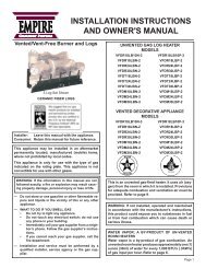
VFD(32,36,42 - White Mountain Hearth
VFD(32,36,42 - White Mountain Hearth
VFD(32,36,42 - White Mountain Hearth

Create successful ePaper yourself
Turn your PDF publications into a flip-book with our unique Google optimized e-Paper software.
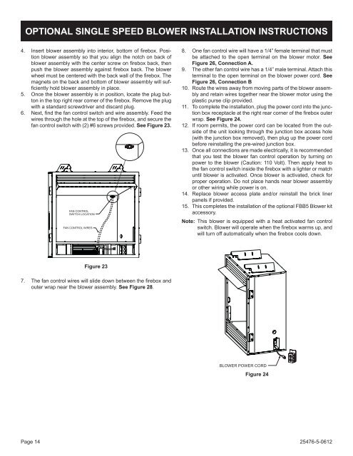
OpTIONAL SINGLE SpEED BLOwER INSTALLATION INSTRUCTIONS<br />
4. Insert blower assembly into interior, bottom of firebox. Position<br />
blower assembly so that you align the notch on back of<br />
blower assembly with the center screw on firebox back, then<br />
push the blower assembly against firebox back. The blower<br />
wheel must be centered with the back wall of the firebox. The<br />
magnets on the back and bottom of blower assembly will sufficiently<br />
hold blower assembly in place.<br />
5. once the blower assembly is in position, locate the plug button<br />
in the top right rear corner of the firebox. Remove the plug<br />
with a standard screwdriver and discard plug.<br />
6. Next, find the fan control switch and wire assembly. Feed the<br />
wires through the hole at the top of the firebox, and secure the<br />
fan control switch with (2) #6 screws provided. See Figure 23.<br />
7. The fan control wires will slide down between the firebox and<br />
outer wrap near the blower assembly. See Figure 28.<br />
Page 14<br />
FAN CONTROL<br />
SWITCH LOCATION<br />
FAN CONTROL WIRES<br />
Figure 23<br />
8. one fan control wire will have a 1/4” female terminal that must<br />
be attached to the open terminal on the blower motor. See<br />
Figure 26, Connection A.<br />
9. the other fan control wire has a 1/4” male terminal. attach this<br />
terminal to the open terminal on the blower power cord. See<br />
Figure 26, Connection B<br />
10. Route the wires away from moving parts of the blower assembly<br />
and retain wires together near the blower motor using the<br />
plastic purse clip provided.<br />
11. to complete the installation, plug the power cord into the junction<br />
box receptacle at the right rear corner of the firebox outer<br />
wrap. See Figure 24.<br />
12. if room permits, the power cord can be located from the outside<br />
of the unit looking through the junction box access hole<br />
(with the junction box removed), then plug up the power cord<br />
before reinstalling the pre-wired junction box.<br />
13. once all connections are made electrically, it is recommended<br />
that you test the blower fan control operation by turning on<br />
power to the blower (caution: 110 Volt). then apply heat to<br />
the fan control switch inside the firebox with a lighter or match<br />
until blower is activated. once blower is activated, check for<br />
proper operation. Do not place hands near blower assembly<br />
or other wiring while power is on.<br />
14. Replace blower access plate and/or reinstall the brick liner<br />
panels if provided.<br />
15. this completes the installation of the optional FBB5 Blower kit<br />
accessory.<br />
Note: this blower is equipped with a heat activated fan control<br />
switch. Blower will operate when the firebox warms up, and<br />
will turn off automatically when the firebox cools down.<br />
BLOWER POWER CORD<br />
Figure 24<br />
25476-5-0612