


Create successful ePaper yourself
Turn your PDF publications into a flip-book with our unique Google optimized e-Paper software.
2.1.2 System Memory Timing Support<br />
The IMC supports the following DDR3 Speed Bin, CAS Write Latency (CWL), and<br />
command signal mode timings on the main memory interface:<br />
Interfaces<br />
• t CL = CAS Latency<br />
• t RCD = Activate Command to READ or WRITE Command delay<br />
• t RP = PRECHARGE Command Period<br />
• CWL = CAS Write Latency<br />
• Command Signal modes = 1N indicates a new command may be issued every clock<br />
and 2N indicates a new command may be issued every 2 clocks. Command launch<br />
mode programming depends on the transfer rate and memory configuration.<br />
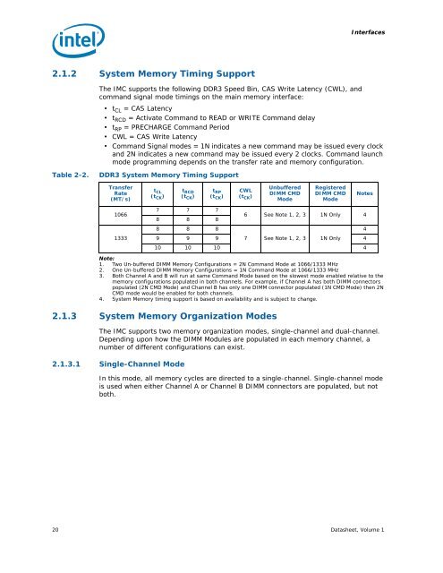
Table 2-2. DDR3 System Memory Timing Support<br />
Transfer<br />
Rate<br />
(MT/s)<br />
1066<br />
1333<br />
t CL<br />
(t CK)<br />
Note:<br />
1. Two Un-buffered DIMM Memory Configurations = 2N Command Mode at 1066/1333 MHz<br />
2. One Un-buffered DIMM Memory Configurations = 1N Command Mode at 1066/1333 MHz<br />
3. Both Channel A and B will run at same Command Mode based on the slowest mode enabled relative to the<br />
memory configurations populated in both channels. For example, if Channel A has both DIMM connectors<br />
populated (2N CMD Mode) and Channel B has only one DIMM connector populated (1N CMD Mode) then 2N<br />
CMD mode would be enabled for both channels.<br />
4. System Memory timing support is based on availability and is subject to change.<br />
2.1.3 System Memory Organization Modes<br />
The IMC supports two memory organization modes, single-channel and dual-channel.<br />
Depending upon how the DIMM Modules are populated in each memory channel, a<br />
number of different configurations can exist.<br />
2.1.3.1 Single-Channel Mode<br />
t RCD<br />
(t CK)<br />
t RP<br />
(t CK)<br />
7 7 7<br />
8 8 8<br />
8 8 8<br />
CWL<br />
(t CK)<br />
Unbuffered<br />
DIMM CMD<br />
Mode<br />
Registered<br />
DIMM CMD<br />
Mode<br />
In this mode, all memory cycles are directed to a single-channel. Single-channel mode<br />
is used when either Channel A or Channel B DIMM connectors are populated, but not<br />
both.<br />
20 Datasheet, Volume 1<br />
Notes<br />
6 See Note 1, 2, 3 1N Only 4<br />
9 9 9 7 See Note 1, 2, 3 1N Only 4<br />
10 10 10 4<br />
4