Hands-On RTAC Session DNP3 Server and Introduction to the Tag Processor Exercise
DNP3 Server and Introduction to the Tag Processor ... - CacheFly
DNP3 Server and Introduction to the Tag Processor ... - CacheFly
- No tags were found...

Create successful ePaper yourself
Turn your PDF publications into a flip-book with our unique Google optimized e-Paper software.
<strong>H<strong>and</strong>s</strong>-<strong>On</strong> <strong>RTAC</strong> <strong>Session</strong><br />
<strong>DNP3</strong> <strong>Server</strong> <strong>and</strong> <strong>Introduction</strong> <strong>to</strong> <strong>the</strong><br />
<strong>Tag</strong> <strong>Processor</strong> <strong>Exercise</strong><br />
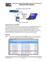
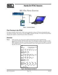
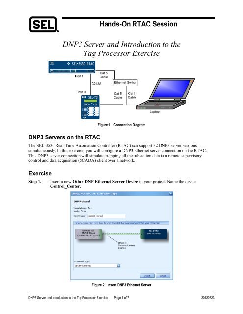
Figure 1<br />
Connection Diagram<br />
<strong>DNP3</strong> <strong>Server</strong>s on <strong>the</strong> <strong>RTAC</strong><br />
The SEL-3530 Real-Time Au<strong>to</strong>mation Controller (<strong>RTAC</strong>) can support 32 <strong>DNP3</strong> server sessions<br />
simultaneously. In this exercise, you will configure a <strong>DNP3</strong> E<strong>the</strong>rnet server connection on <strong>the</strong> <strong>RTAC</strong>.<br />
This <strong>DNP3</strong> server connection will simulate mapping all <strong>the</strong> substation data <strong>to</strong> a remote supervisory<br />
control <strong>and</strong> data acquisition (SCADA) client over a network.<br />
<strong>Exercise</strong><br />
Step 1.<br />
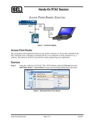
Insert a new O<strong>the</strong>r DNP E<strong>the</strong>rnet <strong>Server</strong> Device in your project. Name <strong>the</strong> device<br />
Control_Center.<br />
Figure 2<br />
Insert <strong>DNP3</strong> E<strong>the</strong>rnet <strong>Server</strong><br />
<strong>DNP3</strong> <strong>Server</strong> <strong>and</strong> <strong>Introduction</strong> <strong>to</strong> <strong>the</strong> <strong>Tag</strong> <strong>Processor</strong> <strong>Exercise</strong> Page 1 of 7 20120723
Step 2.<br />
Under <strong>the</strong> Settings tab, adjust <strong>the</strong> <strong>Server</strong> DNP Address <strong>and</strong> Client DNP Address, as shown<br />
in Figure 3.<br />
When <strong>the</strong> Allow Anonymous DNP IP Clients setting is True, it will allow any Internet<br />
Pro<strong>to</strong>col (IP) address <strong>to</strong> connect. When it is set <strong>to</strong> False, you must enter <strong>the</strong> IP address, or up<br />
<strong>to</strong> ten IP addresses, of <strong>the</strong> <strong>DNP3</strong> clients that will be allowed <strong>to</strong> connect. <strong>On</strong>ly one connection<br />
is supported on <strong>the</strong> server at a time.<br />
Note that <strong>the</strong>re are no tabs for tags for a <strong>DNP3</strong> server connection. Instead, <strong>the</strong>re is a place <strong>to</strong><br />
declare a map, as indicated in Figure 3. Leave this set <strong>to</strong> None until you create <strong>the</strong> <strong>DNP3</strong><br />
map.<br />
Step 3.<br />
Figure 3<br />
<strong>DNP3</strong> Client Settings<br />
Under <strong>Tag</strong> Lists, insert a new <strong>DNP3</strong> Shared <strong>Server</strong> Map called Control_Center.<br />
Figure 4<br />
DNP <strong>Server</strong> Shared Map<br />
<strong>DNP3</strong> <strong>Server</strong> <strong>and</strong> <strong>Introduction</strong> <strong>to</strong> <strong>the</strong> <strong>Tag</strong> <strong>Processor</strong> <strong>Exercise</strong> Page 2 of 7 20120723
Step 4.<br />
In <strong>the</strong> Control_Center_DNP map, under <strong>the</strong> Binary Inputs tab, click on <strong>the</strong> + icon <strong>and</strong> add<br />
100 binary inputs, starting at 0. By default, Event Class for binary inputs should be 1.<br />
Step 5.<br />
Figure 5<br />
Add Binary Inputs<br />
Add 50 analog inputs <strong>to</strong> <strong>the</strong> <strong>DNP3</strong> server starting at 0, as shown in Figure 6. By default, <strong>the</strong><br />
Event Class should be set <strong>to</strong> 2 for analog inputs. Assign <strong>the</strong> Deadb<strong>and</strong> <strong>to</strong> 1 for each point.<br />
Figure 6 <strong>DNP3</strong> <strong>Server</strong> Analog Inputs<br />
Step 6. Add 10 binary outputs <strong>to</strong> <strong>the</strong> <strong>DNP3</strong> server, as shown in Figure 7.<br />
Figure 7<br />
Add Binary Outputs<br />
<strong>DNP3</strong> <strong>Server</strong> <strong>and</strong> <strong>Introduction</strong> <strong>to</strong> <strong>the</strong> <strong>Tag</strong> <strong>Processor</strong> <strong>Exercise</strong> Page 3 of 7 20120723
Step 7.<br />
Now that <strong>the</strong> <strong>DNP3</strong> server shared map has been configured, you can assign <strong>the</strong> map <strong>to</strong> <strong>the</strong><br />
Control_Center_DNP server device under its Settings tab, as shown in Figure 8.<br />
Figure 8<br />
Assign Shared Map <strong>to</strong> <strong>Server</strong><br />
<strong>DNP3</strong> <strong>Server</strong> <strong>and</strong> <strong>Introduction</strong> <strong>to</strong> <strong>the</strong> <strong>Tag</strong> <strong>Processor</strong> <strong>Exercise</strong> Page 4 of 7 20120723
Step 8.<br />
<strong>On</strong>ce <strong>the</strong> <strong>DNP3</strong> server is configured <strong>and</strong> points are assigned, you can use <strong>the</strong> <strong>Tag</strong> <strong>Processor</strong><br />
<strong>to</strong> move <strong>the</strong> information from <strong>the</strong> client connections in<strong>to</strong> <strong>the</strong> server tags. In <strong>the</strong> <strong>Tag</strong><br />
<strong>Processor</strong>, simply enter <strong>the</strong> Control Center tags in <strong>the</strong> Destination <strong>Tag</strong> Name column <strong>and</strong><br />
<strong>the</strong> desired source tags in <strong>the</strong> Source Expression column. Type some tags in by h<strong>and</strong> <strong>to</strong> learn<br />
<strong>the</strong> au<strong>to</strong>matic completion functions, <strong>and</strong> enter o<strong>the</strong>rs by pressing <strong>to</strong> copy <strong>and</strong><br />
<strong>to</strong> paste in<strong>to</strong> <strong>the</strong> <strong>Tag</strong> <strong>Processor</strong>.<br />
Figure 9<br />
<strong>Tag</strong> <strong>Processor</strong><br />
<strong>DNP3</strong> <strong>Server</strong> <strong>and</strong> <strong>Introduction</strong> <strong>to</strong> <strong>the</strong> <strong>Tag</strong> <strong>Processor</strong> <strong>Exercise</strong> Page 5 of 7 20120723
Step 9.<br />
Analog inputs are mapped using <strong>the</strong> same procedure.<br />
Step 10.<br />
Figure 10<br />
Analogs in <strong>Tag</strong> <strong>Processor</strong><br />
Binary outputs or controls are mapped in <strong>the</strong> reverse direction as compared with <strong>the</strong> inputs.<br />
Logically, <strong>the</strong> control signal is coming from a remote <strong>DNP3</strong> client device in<strong>to</strong> <strong>the</strong> <strong>DNP3</strong><br />
server in <strong>the</strong> <strong>RTAC</strong>. This requires <strong>the</strong> Control_Center_DNP server tags be placed in <strong>the</strong><br />
Source Expression side of <strong>the</strong> <strong>Tag</strong> <strong>Processor</strong>. There are many attributes of Control tags,<br />
<strong>and</strong> each can be mapped independently <strong>to</strong> accomplish any task required. Map <strong>the</strong> controls<br />
shown in Figure 11 in<strong>to</strong> your <strong>Tag</strong> <strong>Processor</strong> as an example.<br />
Step 11.<br />
Figure 11<br />
Controls in <strong>the</strong> <strong>Tag</strong> <strong>Processor</strong><br />
The <strong>Tag</strong> <strong>Processor</strong> can be built completely outside of <strong>the</strong> programming software <strong>and</strong> pasted<br />
in after completion. A spreadsheet with a sample <strong>Tag</strong> <strong>Processor</strong> that can be pasted in<strong>to</strong> your<br />
project <strong>to</strong> demonstrate this is available.<br />
<strong>DNP3</strong> <strong>Server</strong> <strong>and</strong> <strong>Introduction</strong> <strong>to</strong> <strong>the</strong> <strong>Tag</strong> <strong>Processor</strong> <strong>Exercise</strong> Page 6 of 7 20120723
Step 12.<br />
Save <strong>and</strong> send your project <strong>to</strong> <strong>the</strong> <strong>RTAC</strong>. Then go online, <strong>and</strong> view <strong>the</strong><br />
Control_Center_DNP tags. Ensure <strong>the</strong>y have good quality <strong>and</strong> are <strong>the</strong> same magnitude as<br />
<strong>the</strong> source data from <strong>the</strong> Feeder_1_SEL <strong>and</strong> Main_BKR_DNP client connections.<br />
Step 13.<br />
Figure 12<br />
<strong>On</strong>line Control Center View<br />
Confirm that <strong>the</strong> controls sent from <strong>the</strong> Control_Center_DNP connection are processed<br />
through <strong>the</strong> <strong>Tag</strong> <strong>Processor</strong> <strong>and</strong> are executed at <strong>the</strong> relay.<br />
Figure 13<br />
Force Controls From <strong>the</strong> Control Center<br />
<strong>DNP3</strong> <strong>Server</strong> <strong>and</strong> <strong>Introduction</strong> <strong>to</strong> <strong>the</strong> <strong>Tag</strong> <strong>Processor</strong> <strong>Exercise</strong> Page 7 of 7 20120723