A Simple Digital VHDL QPSK Modulator Designed Using CPLD ...
A Simple Digital VHDL QPSK Modulator Designed Using CPLD ...
A Simple Digital VHDL QPSK Modulator Designed Using CPLD ...

You also want an ePaper? Increase the reach of your titles
YUMPU automatically turns print PDFs into web optimized ePapers that Google loves.
Proceedings of the World Congress on Engineering 2009 Vol I<br />
WCE 2009, July 1 - 3, 2009, London, U.K.<br />
IV. LE SIMULATION<br />
A. MATLAB/Simulink simulation<br />
The <strong>QPSK</strong> modulator was designed and simulated with<br />
MATLAB/Simulink to verify and validate the modulator<br />
specifications [19]. The modulator is consists of carrier source<br />
to produce a periodic pulse signal ( f ), fed to a carrier<br />
carrier<br />
phase shifter; which shift the input carrier into four different<br />
phase signals (0°, 90°, 180°, 270°) interfaced to multiplexer.<br />
While the data source was generated with PN_suqance, fed to<br />
data mapping to generate I and Q signals to influence the four<br />
phase different carries. The output is selected by multiplexer<br />
which provides digital <strong>QPSK</strong> signal, this signal filtered with<br />
analogue filter before transmitted to pass fundamental<br />
frequency ( fo ± data ) and eliminates the higher frequencies<br />
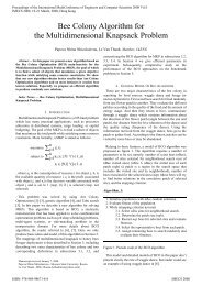
associated with the square signal. The architecture block<br />
diagram of Tx_Mod is shown in Fig .6. The simulated random<br />
data signal (Data_in) which is generated by a PN sequence can<br />
be represented by Fourier series analysis as in Equation (6).<br />
PN( t)<br />
cn<br />
p(<br />
t − nTc<br />
)<br />
n=<br />
−∞<br />
(6)<br />
= ∑ ∞<br />
Where the input carrier signal is a periodic pulse train signal<br />
and mathematically expressed by the Fourier series as in<br />
Equation (7).<br />
4<br />
Carrier ( t ) =<br />
π<br />
∑ ∞<br />
n = 1<br />
sin(( 2 n − 1)<br />
w ct<br />
)<br />
( 2 n − 1)<br />
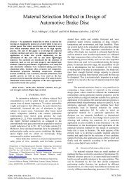
The Tx and the Rx signals are presented in Fig. 5 shows the<br />
spectrum of the transmitted RF signal (CH1) and the received<br />
RF signal (CH2) in the presence of noise (AWGN).<br />
Figure 6. The propoused <strong>Modulator</strong> with Mathlab /simulink daigram<br />
Figure 5. The specrum of <strong>QPSK</strong> transmit and rceive signals<br />
at Data rate 2Mbps,carrier 12.5MHz<br />
ISBN: 978-988-17012-5-1 WCE 2009<br />
(7)