Effect of Hub Motor Mass on Stability and Comfort ... - Protean Electric
Effect of Hub Motor Mass on Stability and Comfort ... - Protean Electric
Effect of Hub Motor Mass on Stability and Comfort ... - Protean Electric

You also want an ePaper? Increase the reach of your titles
YUMPU automatically turns print PDFs into web optimized ePapers that Google loves.
surface. A more in-depth study is required to ascertain the full<br />
effect the added mass has <strong>on</strong> the h<strong>and</strong>ling <str<strong>on</strong>g>of</str<strong>on</strong>g> the vehicle.<br />
F. Force Analysis<br />
St<strong>and</strong>ard vehicle wheels are rigid structures able to<br />
absorb high shock <strong>and</strong> vibrati<strong>on</strong> forces. By using hub motors a<br />
critical system is placed within the wheels <str<strong>on</strong>g>of</str<strong>on</strong>g> the vehicle. It is<br />
important to determine the magnitude <str<strong>on</strong>g>of</str<strong>on</strong>g> the forces exerted <strong>on</strong><br />
the unsprung mass. If these forces are too high <strong>and</strong> are<br />
transferred through the motor, it could lead to quicker wearing<br />
<str<strong>on</strong>g>of</str<strong>on</strong>g> comp<strong>on</strong>ents or even damage to the motor. The forces are<br />
calculated for both single <strong>and</strong> multiple bump road inputs.<br />
Table III <strong>and</strong> IV gives the maximum forces for these cases.<br />
TABLE III<br />
MAXIMUM FORCE EXERTED ON UNSPRUNG MASS (SINGLE BUMP)<br />
Speed St<strong>and</strong>ard <str<strong>on</strong>g>Hub</str<strong>on</strong>g> Driven<br />
5 km/h 1215 N 1984 N<br />
50 km/h 4525 N 4800 N<br />
100 km/h 7475 N 7680 N<br />
TABLE III<br />
MAXIMUM FORCE EXERTED ON UNSPRUNG MASS (MULTI BUMP)<br />
Speed<br />
St<strong>and</strong>ard <str<strong>on</strong>g>Hub</str<strong>on</strong>g> driven<br />
Initial Mag. Freq. Initial Mag. Freq.<br />
5 km/h 1219N 1550N 15.3 Hz 1970N 1775 N 14.3 Hz<br />
50 km/h 4630N 3450N 166.7Hz 5880N 3460N 166.7Hz<br />
100 km/h 8860N 6250N 333.3Hz 8830N 6200N 333.3 Hz<br />
The unsprung mass receives an initial shock force when the<br />
tire hits the first <str<strong>on</strong>g>of</str<strong>on</strong>g> the bumps. This initial force has the same<br />
magnitude as for the case <str<strong>on</strong>g>of</str<strong>on</strong>g> a single bump. After the initial<br />
force, the unsprung mass experiences the vibrati<strong>on</strong>s caused by<br />
traveling across the series <str<strong>on</strong>g>of</str<strong>on</strong>g> bumps. Although the oscillati<strong>on</strong>s<br />
in displacement decrease with an increase in speed, it can be<br />
seen that the force increases with the increase in speed.<br />
At this stage it can not be decided whether the results <str<strong>on</strong>g>of</str<strong>on</strong>g> the<br />
force analysis is within limits. The force exerted <strong>on</strong> the<br />
unsprung mass <str<strong>on</strong>g>of</str<strong>on</strong>g> the hub driven vehicle is not remarkably<br />
higher than that experienced by the st<strong>and</strong>ard vehicle. The <strong>on</strong>ly<br />
way to determine whether or not these results are acceptable is<br />
to investigate the physical structure <str<strong>on</strong>g>of</str<strong>on</strong>g> the hub motor. Finite<br />
element strength analysis can determine if the wheel structure<br />
<strong>and</strong> motor can withst<strong>and</strong> the shock <strong>and</strong> vibrati<strong>on</strong> forces.<br />
VI. FUTURE WORK<br />
The work described in this paper is the first step in studying<br />
the effect <str<strong>on</strong>g>of</str<strong>on</strong>g> the added mass <str<strong>on</strong>g>of</str<strong>on</strong>g> a hub motor <strong>on</strong> the resp<strong>on</strong>se <str<strong>on</strong>g>of</str<strong>on</strong>g><br />
a vehicle’s suspensi<strong>on</strong> system. As menti<strong>on</strong>ed in a previous<br />
secti<strong>on</strong>, the effect <str<strong>on</strong>g>of</str<strong>on</strong>g> vibrati<strong>on</strong>s <strong>on</strong> the structural integrity <str<strong>on</strong>g>of</str<strong>on</strong>g><br />
the hub motor can not be found from the system simulati<strong>on</strong><br />
results. A full strength analysis is to be d<strong>on</strong>e through the use<br />
<str<strong>on</strong>g>of</str<strong>on</strong>g> finite element s<str<strong>on</strong>g>of</str<strong>on</strong>g>tware.<br />
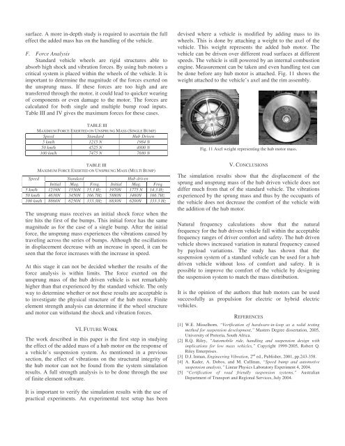
It is important to verify the simulati<strong>on</strong> results with the use <str<strong>on</strong>g>of</str<strong>on</strong>g><br />
practical experiments. An experimental test setup has been<br />
devised where a vehicle is modified by adding mass to its<br />
wheels. This is d<strong>on</strong>e by attaching a weight to the axel <str<strong>on</strong>g>of</str<strong>on</strong>g> the<br />
vehicle. This weight represents the added hub motor. The<br />
vehicle can be driven over different road surfaces at different<br />
speeds. The vehicle is still powered by an internal combusti<strong>on</strong><br />
engine. Measurement can be taken <strong>and</strong> even h<strong>and</strong>ling test can<br />
be d<strong>on</strong>e before any hub motor is attached. Fig. 11 shows the<br />
weight attached to the vehicle’s axel <strong>and</strong> the rim assembly.<br />
Fig. 11 Axel weight representing the hub motor mass.<br />
V. CONCLUSIONS<br />
The simulati<strong>on</strong> results show that the displacement <str<strong>on</strong>g>of</str<strong>on</strong>g> the<br />
sprung <strong>and</strong> unsprung mass <str<strong>on</strong>g>of</str<strong>on</strong>g> the hub driven vehicle does not<br />
differ much from that <str<strong>on</strong>g>of</str<strong>on</strong>g> the st<strong>and</strong>ard vehicle. The vibrati<strong>on</strong>s<br />
experienced by the sprung mass <strong>and</strong> thus by the occupants <str<strong>on</strong>g>of</str<strong>on</strong>g><br />
the vehicle does not decrease the comfort <str<strong>on</strong>g>of</str<strong>on</strong>g> the vehicle with<br />
the additi<strong>on</strong> <str<strong>on</strong>g>of</str<strong>on</strong>g> the hub motor.<br />
Natural frequency calculati<strong>on</strong>s show that the natural<br />
frequency for the hub driven vehicle fall within the acceptable<br />
frequency ranges <str<strong>on</strong>g>of</str<strong>on</strong>g> driver comfort <strong>and</strong> safety. The hub driven<br />
vehicle shows increased variati<strong>on</strong> in natural frequency caused<br />
by payload variati<strong>on</strong>s. The study has shown that the<br />
suspensi<strong>on</strong> system <str<strong>on</strong>g>of</str<strong>on</strong>g> a st<strong>and</strong>ard vehicle can be used for a hub<br />
driven vehicle without loss <str<strong>on</strong>g>of</str<strong>on</strong>g> comfort <strong>and</strong> safety. It is<br />
possible to improve the comfort <str<strong>on</strong>g>of</str<strong>on</strong>g> the vehicle by designing<br />
the suspensi<strong>on</strong> system to match the mass distributi<strong>on</strong>.<br />
It is the opini<strong>on</strong> <str<strong>on</strong>g>of</str<strong>on</strong>g> the authors that hub motors can be used<br />
successfully as propulsi<strong>on</strong> for electric or hybrid electric<br />
vehicles.<br />
REFERENCES<br />
[1] W.E. Misselhorn, “Verificati<strong>on</strong> <str<strong>on</strong>g>of</str<strong>on</strong>g> hardware-in-loop as a valid testing<br />
method for suspensi<strong>on</strong> development,” Masters Degree dissertati<strong>on</strong>, 2005,<br />
University <str<strong>on</strong>g>of</str<strong>on</strong>g> Pretoria, South Africa.<br />
[2] R.Q. Riley, “Automobile ride, h<strong>and</strong>ling <strong>and</strong> suspensi<strong>on</strong> design with<br />
implicati<strong>on</strong>s for low mass vehicles,” Copyright 1999-2005, Robert Q.<br />
Riley Enterprises.<br />
[3] D.J. Inman, Engineering Vibrati<strong>on</strong>, 2 nd ed., Publisher, 2001, pp.243-358.<br />
[4] A. Kader, A. Dobos, <strong>and</strong> M. Cullinan, “Speed bump <strong>and</strong> automotive<br />
suspensi<strong>on</strong> analysis,” Linear Physics Laboratory Experiment 4, 2004.<br />
[5] “Certificati<strong>on</strong> <str<strong>on</strong>g>of</str<strong>on</strong>g> road friendly suspensi<strong>on</strong> systems,” Australian<br />
Department <str<strong>on</strong>g>of</str<strong>on</strong>g> Transport <strong>and</strong> Regi<strong>on</strong>al Services, July 2004.