UltraLight Steel Auto Body - Final Report - American Iron & Steel ...
UltraLight Steel Auto Body - Final Report - American Iron & Steel ...
UltraLight Steel Auto Body - Final Report - American Iron & Steel ...

You also want an ePaper? Increase the reach of your titles
YUMPU automatically turns print PDFs into web optimized ePapers that Google loves.
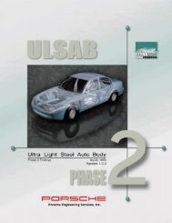
<strong>UltraLight</strong> <strong>Steel</strong> <strong>Auto</strong> <strong>Body</strong> <strong>Final</strong> <strong>Report</strong><br />
Research conducted by the <strong>UltraLight</strong> <strong>Steel</strong> <strong>Auto</strong> <strong>Body</strong> Consortium. This <strong>Final</strong> <strong>Report</strong><br />
published by <strong>American</strong> <strong>Iron</strong> and <strong>Steel</strong> Institute.<br />
First Edition<br />
<strong>American</strong> <strong>Iron</strong> and <strong>Steel</strong> Institute<br />
Washington, D.C.
ii<br />
Copyright © <strong>American</strong> <strong>Iron</strong> & <strong>Steel</strong> Institute<br />
This publication is for general information only. The information in<br />
it should not be used without first securing competent advice with<br />
respect to its suitability for any given application. The publication<br />
of the information is not intended as a representation or warranty<br />
on the part of the <strong>American</strong> <strong>Iron</strong> and <strong>Steel</strong> Institute - or any other<br />
person named herein - that the information is suitable for any<br />
general or particular use of freedom from infringement of any<br />
patent or patents. Anyone making use of the information assumes<br />
all liability arising from such use.<br />
March, 1998
Contents<br />
Preface v<br />
Introduction vii<br />
<strong>UltraLight</strong> <strong>Steel</strong> <strong>Auto</strong> <strong>Body</strong> Consortium ix<br />
1. Design 1<br />
1.1 Benchmarking 1<br />
1.2 Design philosophy and architecture 3<br />
1.3 Packaging 3<br />
1.4 Styling 6<br />
1.5 Material selection 7<br />
1.6 ULSAB in detail 10<br />
2. Materials and Processes 15<br />
2.1 Materials 15<br />
2.1.1 High strength steel 15<br />
2.1.2 Tailored blanks 16<br />
2.1.3 <strong>Steel</strong> sandwich 19<br />
2.2 Processes 19<br />
2.2.1 Hydroforming 19<br />
2.2.2 Assembly laser welding 21<br />
3. Manufacturing 23<br />
3.1 Early involvement 23<br />
3.2 Tooling 23<br />
3.3 Analysis 23<br />
3.4 Part validation 24<br />
3.5 Assembly 24<br />
3.5.1 Sequence 24<br />
3.5.2 Adhesive bonding 27<br />
iii
4. Structural Performance 29<br />
4.1 Validation 29<br />
4.2 CAE Analysis 29<br />
4.2.1 Static and modal analysis 30<br />
4.2.2 Crash analysis 30<br />
4.3 Physical testing 39<br />
4.3.1 Static torsion test 39<br />
4.3.2 Static bending test 39<br />
4.3.3 Modal test 40<br />
4.4 Results and prediction 41<br />
4.5 Structural performance 42<br />
4.6 <strong>Body</strong> structure 42<br />
5. Economic Analysis 43<br />
iv<br />
5.1 General inputs 44<br />
5.2 Production costs 44<br />
5.2.1 Fabrication 44<br />
5.2.2 Assembly 44<br />
5.3 Model scope 45<br />
5.4 ULSAB results 45<br />
5.4.1 Fabrication breakdown 46<br />
5.4.2 Assembly breakdown 46<br />
5.4.3 Investments 47<br />
5.5 Sensitivity analysis 47<br />
5.6 Comparison 48<br />
5.7 Conclusion 50
Preface<br />
One of the challenges in reporting on a project of the size and<br />
scope of the <strong>UltraLight</strong> <strong>Steel</strong> <strong>Auto</strong> <strong>Body</strong> is deciding how to present<br />
results, particularly considering the diversity of audiences who are<br />
interested in the project’s outcomes. This project generated a<br />
wealth of technical data, most of which is summarized in this<br />
report. More detailed information is contained in a CD-ROM<br />
entitled <strong>UltraLight</strong> <strong>Steel</strong> <strong>Auto</strong> <strong>Body</strong> Electronic <strong>Report</strong>, which is<br />
available from <strong>American</strong> <strong>Iron</strong> and <strong>Steel</strong> Institute. In addition to this,<br />
North <strong>American</strong> steel industry automotive applications engineers<br />
will bring to North <strong>American</strong> automakers complete design,<br />
manufacturing and cost analysis details. For more information, call<br />
1-800-STEELWORKS.<br />
This report offers substantial technical detail but it is presented in<br />
such a manner to allow non-engineers a working understanding of<br />
the project and its results. It covers concept, design,<br />
manufacturing, cost, materials and a structural analysis of the<br />
project. For the engineer, this report provides an in-depth<br />
overview with sufficient detail to support the findings. It contains<br />
discussion of key aspects of the project along with numerous<br />
tables, charts and illustrations.<br />
v
Background<br />
Concept<br />
Introduction<br />
A consortium of 35 sheet steel producers from 18 countries<br />
around the world has set new standards for successful<br />
collaboration as well as automotive body design. Four years ago,<br />
fierce competitors joined together in a common purpose. Today<br />
they present the culmination of their teamwork: a lightweight steel<br />
auto body structure that outperforms benchmarked averages and<br />
can also cost less to build.<br />
The <strong>UltraLight</strong> <strong>Steel</strong> <strong>Auto</strong> <strong>Body</strong> (ULSAB) Consortium was formed<br />
to answer the challenge of car makers around the world: reduce<br />
the weight of steel auto body structures while maintaining their<br />
performance and affordability. This seemingly simple request<br />
required a concerted effort by the most prominent steel<br />
manufacturers in the world if it were to be answered satisfactorily.<br />
Sheet steel producers from around the world joined the<br />
consortium to design and validate an <strong>UltraLight</strong> <strong>Steel</strong> <strong>Auto</strong> <strong>Body</strong>.<br />
The ULSAB Consortium contracted Porsche Engineering<br />
Services, Inc. (PES) to provide engineering and manufacturing<br />
management for the ULSAB project and worked with them to<br />
define the project goals. They took a two-phase approach: The<br />
concept phase encompassed a clean-sheet design of a<br />
lightweight steel auto structure; the validation phase verified the<br />
design through the manufacture of ULSAB structures.<br />
The Consortium was an ingenious way to leverage funds and<br />
resources. The ULSAB project, which has cost $22 million and<br />
spanned almost four years, was too large for a single steel<br />
company — or even a single region. Consortium members<br />
contributed their time and expertise to ensure the success of this<br />
important project.<br />
After benchmarking nine mid-size sedans from manufacturers<br />
around the world, PES developed mass and performance targets<br />
for the ULSAB structure. Throughout the design process, PES<br />
consulted with materials, manufacturing and assembly experts to<br />
ensure that the design could be built using near-reach<br />
technologies and available materials.<br />
In September 1995, the Consortium announced the results of the<br />
concept phase. The design of ULSAB indicated a weight savings<br />
of up to 36 percent and substantially improved performance when<br />
compared to benchmarked averages in the same class. An<br />
independent cost study indicated ULSAB should also cost less to<br />
produce than typical vehicle structures of that time.<br />
<strong>Auto</strong>makers and the media from around the world responded with<br />
great enthusiasm to the results of this unprecedented steel<br />
industry cooperative initiative. The story was covered in virtually<br />
every member country, much to the satisfaction of the<br />
Consortium.<br />
vii
viii<br />
Validation<br />
Results<br />
During the validation phase in late fall 1995, design and<br />
engineering of the ULSAB body structure were refined and<br />
finalized. The Consortium then approved a $20 million body<br />
structure build phase to validate the concept. Strategies were<br />
developed to communicate the progress during and at the<br />
conclusion of the project.<br />
Exterior styling was developed to create a recognizable look for<br />
the auto structure. Consortium members provided material for the<br />
parts, and component fabricators were selected to build the<br />
components. Assembly and testing of the body structures took<br />
place at Porsche in Germany. Also, a Porsche-led team of<br />
analysts conducted an in-depth economic analysis of the cost of<br />
ULSAB.<br />
Results of the validation of ULSAB were announced to the world<br />
in March 1998: The ULSAB structure weighs merely 203 kg, or<br />
up to 36 percent less than the heaviest of the benchmarked<br />
vehicles. Physical tests of the structure reveal similar remarkable<br />
results: torsion and bending tests showed improvements over<br />
benchmark of 80 percent and 52 percent, respectively, and 1st<br />
body structure mode indicates a 58 percent improvement.<br />
Analyses also show ULSAB satisfies mandated crash<br />
requirements, even at speeds exceeding some of the<br />
requirements. In addition to reduced weight and superior<br />
performance, ULSAB costs no more to build than typical auto<br />
body structures in its class and can even yield potential cost<br />
savings, according to economic analysis.<br />
The ULSAB project employs many techniques and processes that<br />
were unique and deemed patentable by international attorneys.<br />
The Consortium chose to make all patentable features along with<br />
other project results freely available to its customers and to the<br />
public. All intellectual property generated by ULSAB has been<br />
placed in the public domain.<br />
ULSAB is a vivid example of the power of international, interindustry<br />
cooperation. The cooperative efforts of design engineers,<br />
steel producers, component fabricators, assembly experts and<br />
economists who worked on the project illustrate that automakers<br />
can retain the benefits of steel while realizing substantial mass<br />
reductions and increasing the performance of auto structures.
<strong>UltraLight</strong> <strong>Steel</strong> <strong>Auto</strong> <strong>Body</strong> Consortium<br />
ACERALIA Corporación Siderurgica, S.A.<br />
AK <strong>Steel</strong> Corporation<br />
Bethlehem <strong>Steel</strong> Corporation<br />
BHP <strong>Steel</strong><br />
British <strong>Steel</strong> plc<br />
Cockerill Sambre, S.A.<br />
Companhia Siderurgica Nacional (CSN)<br />
Dofasco Inc.<br />
Hoogovens Stahl BV<br />
Inland <strong>Steel</strong> Company<br />
Kawasaki <strong>Steel</strong> Corporation<br />
Kobe <strong>Steel</strong>, Ltd.<br />
Krupp Hoesch Stahl AG/Krupp Hoesch <strong>Auto</strong>motive GmbH<br />
LTV <strong>Steel</strong> Company, Inc.<br />
National <strong>Steel</strong> Corporation<br />
Nippon <strong>Steel</strong> Corporation<br />
NKK Corporation<br />
Pohang <strong>Iron</strong> and <strong>Steel</strong> Co., Ltd. (POSCO)<br />
Preussag Stahl AG<br />
PT Krakatau <strong>Steel</strong><br />
Rouge <strong>Steel</strong> Company<br />
SIDERAR S.A.I.C.<br />
SIDMAR NV<br />
SOLLAC - Usinor Sacilor Group<br />
SSAB Tunnplät AB<br />
Stelco Inc.<br />
Sumitomo Metal Industries, Ltd.<br />
The Tata <strong>Iron</strong> and <strong>Steel</strong> Company, Ltd. (TISCO)<br />
Thyssen Stahl AG<br />
U.S. <strong>Steel</strong> Group (USX Corporation)<br />
Usinas Siderurgicas de Minas Gerais (USIMINAS)<br />
VOEST-ALPINE STAHL LINZ GmbH<br />
VSZ a.s. Kosice<br />
WCI <strong>Steel</strong>, Inc.<br />
Weirton <strong>Steel</strong> Corporation<br />
ix
1.1 Benchmarking<br />
ULSAB <strong>Final</strong> <strong>Report</strong><br />
The first objective of the <strong>UltraLight</strong> <strong>Steel</strong> <strong>Auto</strong> <strong>Body</strong> (ULSAB)<br />
Consortium was to design a lightweight steel body structure that<br />
would meet increased functional and structural performance<br />
targets while remaining affordable. The consortium also specified<br />
that, while the design should be leading edge, it must also be<br />
feasible using near-reach manufacturing processes.<br />
Porsche Engineering Services, Inc. (PES) benchmarked nine<br />
mid-sized sedans to determine current performance against<br />
which to measure ULSAB. PES also established package<br />
constraints through this benchmarking process. To determine an<br />
“average base model,” 32 different cars that represent varying<br />
worldwide customer requirements were selected for package<br />
benchmarking. Benchmarking considered curb weight;<br />
wheelbase; overall length and width; leg, head and shoulder<br />
room; passenger compartment; and cargo volume. Benchmarking<br />
established the following package specifications:<br />
Package benchmark specifications<br />
1. Design<br />
body type 4-door sedan headroom<br />
front/rear<br />
960/940 mm<br />
wheelbase 2700 mm leg room<br />
front/rear<br />
1060/890 mm<br />
overall length 4800 mm shoulder<br />
room f/r<br />
1420/1400 mm<br />
overall width 1800 mm cargo volume 425 liters<br />
curb weight 1350 kg engine type V6<br />
passenger 5 drive front<br />
For structural benchmarking (static torsion, static bending, 1st<br />
body structure mode), PES used a cross section of nine cars that<br />
represented current performance standards. These vehicles<br />
included the:<br />
� Acura Legend<br />
� BMW 5-series<br />
� Chevrolet Lumina<br />
� Ford Taurus<br />
� Honda Accord<br />
� Lexus LS 400<br />
� Mazda 929<br />
� Mercedes 190 E<br />
� Toyota Cressida<br />
1
2<br />
To make a direct correlation in performance among the above nine<br />
vehicles, PES adjusted the structural performance linearly to the<br />
ULSAB target wheelbase of 2700 mm. PES employed the<br />
following equation for this adjustment:<br />
C adjusted = C actual Wheelbase reference vehicle<br />
Wheelbase ULSAB<br />
where C adjusted = adjusted stiffness of reference vehicle<br />
and C actual = actual stiffness of reference vehicle<br />
These vehicles were also normalized for mass by comparing the<br />
interior body volumes with the projected area (length multiplied by<br />
width). Volume of these vehicles was determined using SAE<br />
Standard 1100a, which states that the usable volume in the front<br />
(V1) and the usable passenger compartment volume (V2) and the<br />
usable luggage volume (V3) add up to the entire usable volume<br />
(Vtotal) of the vehicle:<br />
V1 + V2 + V3 = V total<br />
This benchmarking exercise generated the following performance<br />
averages:<br />
Benchmark performance<br />
static torsional rigidity 11,531 Nm/deg<br />
static bending rigidity 11,902 N/mm<br />
1st body structure mode 38 Hz<br />
mass 271 kg<br />
This information was then used to predict a future reference<br />
vehicle with improved performance with which ULSAB must<br />
ultimately compare. Assumptions for that future reference vehicle<br />
were as follows:<br />
Future reference structure performance<br />
static torsional rigidity 13,000 Nm/deg<br />
static bending rigidity 12,200 N/mm<br />
1st body structure mode 40 Hz<br />
mass 250 kg<br />
ULSAB <strong>Final</strong> <strong>Report</strong>
1.2 Design philosophy and architecture<br />
1.3 Packaging<br />
PES determined to employ an holistic philosophy toward design<br />
early in the design process. This holistic approach treats the<br />
body structure as an integrated system rather than an assembly<br />
of individual components, emphasizing total body analysis.<br />
Through each iterative step, sophisticated computer re-analysis<br />
confirms the effectiveness of the latest optimizations. The holistic<br />
approach also allows evaluation of how other areas are affected<br />
by these changes and where future optimization opportunities<br />
exist. This approach promotes weight savings and improved<br />
structural integrity by enabling engineers to reduce weight in<br />
certain areas while strengthening strategic locations. The net<br />
effect is the creation of a more efficient structure.<br />
PES investigated various concepts to develop the optimum<br />
ULSAB body structure. Some of these included full frame, space<br />
frame, unibody and hybrid solutions. Criteria for the structures<br />
under consideration were significant weight savings potential,<br />
opportunity to achieve performance targets and assembly<br />
possibilities in future full volume production body shops.<br />
Early in the project PES engineers eliminated the full frame<br />
concept because it offered no significant mass saving<br />
opportunities. They also doubted that the full frame would meet<br />
ULSAB’s structural performance criteria and were concerned<br />
about high investment costs for assembly. Although a<br />
spaceframe was considered, it was ultimately eliminated<br />
because it was not considered as mass efficient as other<br />
approaches. The PES team ultimately narrowed its investigation<br />
to two structures—a unibody and a hydroform-intensive body<br />
structure—finally settling on creating a unibody or monocoque<br />
vehicle with key hydroformed parts.<br />
The first step in packaging was to define the vehicle concept<br />
type, exterior and interior dimensions and main components.<br />
With these package definitions, package drawings were created<br />
and structural hard points defined. ULSAB did not save mass<br />
through downsizing: its wheelbase is 2700 mm; vehicle width is<br />
1819 mm; and vehicle length is 4714 mm.<br />
ULSAB <strong>Final</strong> <strong>Report</strong> 3
4<br />
Package specifications for ULSAB are:<br />
ULSAB package<br />
body type 4-door sedan headroom 994/932 mm<br />
front/rear<br />
wheelbase 2700 mm leg room<br />
front/rear<br />
1043/894 mm<br />
overall length 4714 mm shoulder<br />
room f/r<br />
1512/1522 mm<br />
overall width 1819 mm cargo volume 490 liters<br />
curb weight 1350 kg engine type 3 liter V6<br />
passenger 5 drive front<br />
radiator size 0.252 m2 exhaust system single routing<br />
battery 280 X 170 suspension McPherson<br />
(in mm) X 170 front<br />
suspension<br />
rear<br />
twist beam tire size (f & r) 195/60R15<br />
spare tire space saver fuel tank<br />
volume<br />
65 liters<br />
steering rack & pinion<br />
The ULSAB package drawings comprehend all essential parts of<br />
the structure interior. Criteria for interior design included visibility,<br />
obscuration by the pillars, head clearance and seat belt anchors.<br />
In the engine compartment, the engine, gearbox, exhaust system,<br />
radiator and battery were used to define space for the structural<br />
members of the front body structure.<br />
ULSAB package drawing side view<br />
ULSAB <strong>Final</strong> <strong>Report</strong>
ULSAB package drawing front view<br />
ULSAB package drawing rear view<br />
ULSAB package drawing plan view<br />
ULSAB <strong>Final</strong> <strong>Report</strong> 5
6<br />
1.4 Styling<br />
The ULSAB project also comprehended styling issues. Exterior<br />
styling of ULSAB was used to create surfaces for design. Styling<br />
also gave it a look that is easily recognized and afforded the<br />
opportunity to conduct closure design studies, the results of<br />
which will be made available in the future.<br />
Demonstrating exterior styling posed certain challenges. The<br />
styling had to follow precisely the engineering design of ULSAB.<br />
And, while not attempting to provide leading-edge styling, the<br />
results had to illustrate the highest quality surfaces typical of<br />
steel-skinned vehicles, which global audiences have come to<br />
expect.<br />
ULSAB styling was entirely computer-aided using ALIAS Studio<br />
Paint Software for the creation of two-dimensional sketches and<br />
ULSAB styling<br />
Pro-Designer for renderings and three-dimensional modeling.<br />
CATIA was used for the final surfacing on the ‘A’ class surfaces.<br />
In the studio, the CATIA package data was imported into a threedimensional<br />
concept modeling software called CDRS, and a side<br />
view outline drawing was developed for sketching purposes.<br />
ULSAB <strong>Final</strong> <strong>Report</strong>
1.5 Material selection<br />
The selection of appropriate materials was based on<br />
considerations of mass, performance, and crash requirements. In<br />
an effort to optimize the best attributes of steel in this project,<br />
PES engineers specified unusually large percentages of high and<br />
ultra high strength steels, tailored blanks and steel sandwich<br />
material. The materials for the body were chosen to meet mass<br />
and performance targets and include some grades and<br />
thicknesses of steel currently available but not commonly used in<br />
auto bodies.<br />
ULSAB uses high strength steel and ultra high strength steel for<br />
more than 90 percent of the body structure to improve structural<br />
High strength steel usage (shaded)<br />
ULSAB <strong>Final</strong> <strong>Report</strong> 7
8<br />
Nearly half of ULSAB’s mass consists of parts that require tailored<br />
blanks, which enable the design engineer to locate various steels<br />
within the part precisely where their attributes are most needed,<br />
thereby removing mass that does not contribute to performance.<br />
Tailored blank usage (shaded)<br />
ULSAB also features a hydroformed side roof rail, which provides<br />
an essential load path for structural performance and crash energy<br />
management from the top of the ‘A’ pillar along the roof, into the<br />
‘B’ and ‘C’ pillars and into the rear of the structure. In addition to<br />
tubular hydroforming, ULSAB uses sheet hydroforming for the roof<br />
panel. The work hardening effect produces improved dent<br />
resistance in the formed part, especially in the center of the panel.<br />
ULSAB <strong>Final</strong> <strong>Report</strong>
<strong>Steel</strong> sandwich material was chose for mass reduction in the spare<br />
tire tub and dash panel.<br />
Hydroformed tubing and steel sandwich material usage (shaded)<br />
These advanced materials and processes enabled the design<br />
engineers to consolidate functions in fewer parts, reducing<br />
ULSAB’s part count to 96 major parts and 158 total parts, as<br />
compared with more than 200 total parts for an existing typical<br />
body structure in the same class. Reduced part count leads to<br />
reduced tooling and assembly costs. This function consolidation<br />
also leads to mass savings and improved structural performance.<br />
ULSAB <strong>Final</strong> <strong>Report</strong> 9
10<br />
1.6 ULSAB in detail<br />
176 178<br />
176 179<br />
72<br />
98<br />
142<br />
176 178<br />
176 179<br />
57<br />
55<br />
50<br />
140<br />
190<br />
14<br />
82<br />
46<br />
48<br />
68<br />
70<br />
102 116 110 180<br />
80<br />
81<br />
69<br />
83<br />
117<br />
47 49<br />
15<br />
152<br />
90<br />
130<br />
91<br />
122<br />
42<br />
64<br />
62<br />
74<br />
144<br />
60<br />
66<br />
128<br />
45<br />
Below is an exploded view of the ULSAB structure with numbers<br />
and corresponding parts list:<br />
38<br />
40<br />
120<br />
34<br />
87 85<br />
142<br />
86<br />
99<br />
71<br />
103<br />
73<br />
65<br />
110<br />
181<br />
122<br />
38<br />
115<br />
22<br />
21<br />
170<br />
32<br />
28<br />
2<br />
12<br />
108<br />
96<br />
104<br />
106<br />
136<br />
171<br />
172<br />
61<br />
145<br />
75<br />
63<br />
66<br />
43<br />
164<br />
8<br />
177 178<br />
177 179<br />
3<br />
13 11<br />
26<br />
10<br />
1<br />
177 178<br />
177 179<br />
9<br />
109<br />
94<br />
97<br />
107<br />
105<br />
188<br />
165<br />
ULSAB <strong>Final</strong> <strong>Report</strong><br />
95
ULSAB parts list<br />
Material Material<br />
Part Grade Thickness<br />
No Part Name (MPa) (mm)<br />
001 Assy Reinf Radiator Support Upper 350 1.00<br />
002 Reinf Front Rail Extension RH 350 1.00<br />
003 Reinf Front Rail Extension LH 350 1.00<br />
008 A Assy Rail Front Outer RH 350 1.50<br />
B (Tailored Blank) 350 1.60<br />
C 350 2.00<br />
009 A Assy Rail Front Outer LH 350 1.50<br />
B (Tailored Blank) 350 1.60<br />
C 350 2.00<br />
010 A Assy Rail Front Inner RH 350 1.50<br />
B (Tailored Blank) 350 1.60<br />
C 350 1.80<br />
011 A Assy Rail Front Inner LH 350 1.50<br />
B (Tailored Blank) 350 1.60<br />
C 350 1.80<br />
012 Rail Front Extension RH 350 1.40<br />
013 Rail Front Extension LH 350 1.40<br />
014 Bracket Roof Rail Mount Lower RH 350 1.20<br />
015 Bracket Roof Rail Mount Lower LH 350 1.20<br />
021 Panel Dash 210 0.70<br />
022 Panel Dash Insert Sandwich 0.95<br />
026 Member Dash Front 600 1.20<br />
028 Panel Cowl Lower 210 0.70<br />
032 Panel Cowl Upper 210 0.70<br />
034 Assy Member Front Floor Support (2-Req’d) 800 0.70<br />
038 Assy Reinf Floor Front Seat Rear Outer (2-Req’d) 280 0.80<br />
040 Pan Front Floor 210 0.70<br />
042 A Panel Rocker Inner RH 350 1.30<br />
B (Tailored Blank) 350 1.70<br />
043 A Panel Rocker Inner LH 350 1.30<br />
B (Tailored Blank) 350 1.70<br />
045 Member Rear Suspension 280 0.70<br />
046 A Assy Rail Rear Inner RH 350 1.00<br />
B (Tailored Blank) 350 1.30<br />
C 350 1.60<br />
047 A Assy Rail Rear Inner LH 350 1.00<br />
B (Tailored Blank) 350 1.30<br />
C 350 1.60<br />
048 A Assy Rail Rear Outer RH 350 1.00<br />
B (Tailored Blank) 350 1.30<br />
C 350 1.60<br />
049 A Assy Rail Rear Outer LH 350 1.00<br />
B (Tailored Blank) 350 1.30<br />
C 350 1.60<br />
050 Panel Spare Tire Tub Sandwich 0.96<br />
055 Member Panel Back 210 0.65<br />
057 Panel Back 140 0.65<br />
ULSAB <strong>Final</strong> <strong>Report</strong> 11
12<br />
ULSAB parts list (cont.)<br />
Material Material<br />
Part Grade Thickness<br />
No Part Name (MPa) (mm)<br />
060 A Panel <strong>Body</strong> Side Outer RH 210 0.70<br />
B (Tailored Blank) 280 0.90<br />
C 280 1.30<br />
D 350 1.50<br />
E 350 1.70<br />
061 A Panel <strong>Body</strong> Side Outer LH 210 0.70<br />
B (Tailored Blank) 280 0.90<br />
C 280 1.30<br />
D 350 1.50<br />
E 350 1.70<br />
062 Panel A-Pillar Inner Lower RH 350 1.00<br />
063 Panel A-Pillar Inner Lower LH 350 1.00<br />
064 Panel B-Pillar Inner RH 350 1.50<br />
065 Panel B-Pillar Inner LH 350 1.50<br />
066 Reinf B-Pillar Lower (2-Req’d) 350 0.90<br />
068 Panel Wheelhouse Inner RH 210 0.65<br />
069 Panel Wheelhouse Inner LH 210 0.65<br />
070 A Panel Wheelhouse Outer RH 140 0.65<br />
B (Tailored Blank) 210 0.80<br />
071 A Panel Wheelhouse Outer LH 140 0.65<br />
B (Tailored Blank) 210 0.80<br />
072 Rail Side Roof RH 280 1.00<br />
073 Rail Side Roof LH 280 1.00<br />
074 Panel A-Pillar Inner Upper RH 350 1.50<br />
075 Panel A-Pillar Inner Upper LH 350 1.50<br />
080 Panel Package Tray Upper 210 0.65<br />
081 Panel Package Tray Lower 210 0.65<br />
082 Support Package Tray RH 280 0.80<br />
083 Support Package Tray LH 280 0.80<br />
085 Panel Roof 210 0.70<br />
086 Panel Front Header 280 0.70<br />
087 Panel Rear Header 140 0.70<br />
090 Member Pass Through (2-Req’d) 140 0.65<br />
091 Member Kick Up 800 0.70<br />
094 Reinf Radiator Rail Closeout RH 350 1.00<br />
095 Reinf Radiator Rail Closeout LH 350 1.00<br />
096 A Panel Skirt RH 140 2.00<br />
B (Tailored Blank) 140 1.60<br />
097 A Panel Skirt LH 140 2.00<br />
B (Tailored Blank) 140 1.60<br />
098 Panel Gutter Decklid RH 140 0.65<br />
099 Panel Gutter Decklid LH 140 0.65<br />
102 Support Panel Rear Header RH 140 0.70<br />
103 Support Panel Rear Header LH 140 0.70<br />
104 Rail Fender Support Inner RH 420 1.20<br />
ULSAB <strong>Final</strong> <strong>Report</strong>
ULSAB parts list (cont.)<br />
Material Material<br />
Part Grade Thickness<br />
No Part Name (MPa) (mm)<br />
105 Rail Fender Support Inner LH 420 1.20<br />
106 Rail Fender Support Outer RH 350 0.90<br />
107 Rail Fender Support Outer LH 350 0.90<br />
108 Reinf Front Rail RH 350 1.00<br />
109 Reinf Front Rail LH 350 1.00<br />
110 Plate Rear Spring Upper (2-Req’d) 350 2.00<br />
115 Reinf Panel Dash Brake Booster 350 1.00<br />
116 Assy Bracket Rear Shock Absorber Mount RH 350 2.00<br />
117 Assy Bracket Rear Shock Absorber Mount LH 350 2.00<br />
120 Reinf Floor Front Seat Rear Center 350 1.20<br />
122 Assy Reinf Rear Seat Inner Belt Mount (2-Req’d) 350 2.00<br />
128 Bracket Member Pass Through Lower (2-Req’d) 350 1.00<br />
130 Bracket Member Pass Through Upper Front 350 1.00<br />
136 Reinf Panel Dash Upper 350 1.00<br />
140 Pan Rear Floor 210 0.70<br />
142 Assy Reinf Hinge Decklid (2-Req’d) 350 1.50<br />
144 Reinf A-Pillar RH 350 1.50<br />
145 Reinf A-Pillar LH 350 1.50<br />
152 Bracket Member Pass Through Upper Rear 350 1.00<br />
164 Assy Closeout Fender Support Rail RH 350 1.00<br />
165 Assy Closeout Fender Support Rail LH 350 1.00<br />
170 Reinf Rail Dash RH 350 1.30<br />
171 Reinf Rail Dash LH 350 1.30<br />
172 Assy Reinf Cowl Lower 350 1.00<br />
176 Hinge Base RH (2-Req’d) 280 n/a<br />
177 Hinge Base LH (2-Req’d) 280 n/a<br />
178 Hinge Stem 119 (2-Req’d) 280 n/a<br />
179 Hinge Stem 141 (2-Req’d) 280 n/a<br />
180 Bracket Trailing Arm Mount RH 350 2.00<br />
181 Bracket Trailing Arm Mount LH 350 2.00<br />
188 Brace Radiator (2-Req’d) 350 0.80<br />
190 Assy Reinf Seat Belt Retractor Rear (2-Req’d) 350 1.20<br />
ULSAB <strong>Final</strong> <strong>Report</strong> 13
14<br />
ULSAB <strong>Final</strong> <strong>Report</strong>
280 MPa<br />
2.1 Materials<br />
210 MPa<br />
ULSAB <strong>Final</strong> <strong>Report</strong><br />
350 MPa<br />
2.1.1 High strengh steel<br />
Mild <strong>Steel</strong><br />
<strong>Steel</strong> Sandwich<br />
UHSS<br />
420 MPa<br />
Materials usage<br />
2. Materials and Processes<br />
The <strong>UltraLight</strong> <strong>Steel</strong> <strong>Auto</strong> <strong>Body</strong> (ULSAB) design called for the<br />
application of some steel thicknesses and grades currently<br />
available but not commonly used in automotive bodies, as well as<br />
the use of advanced manufacturing processes. <strong>Steel</strong> is the most<br />
recycled material in the world, and all steel chosen for the ULSAB<br />
structure is recyclable. <strong>Steel</strong> specifications for the body were<br />
chosen to meet mass, performance and safety goals.<br />
In their effort to optimize the best attributes of steel in this project,<br />
PES engineers specified unusually large percentages of high and<br />
ultra high strength steels and steel sandwich material. They also<br />
called for the use of hydroforming and tailored blanking.<br />
Conventional<br />
Blank Stamping<br />
Sheet Hydroforming<br />
Tubular Hydroforming<br />
Miscellaneous<br />
<strong>Steel</strong> Sandwich<br />
Stamping<br />
Tailored Blank<br />
Stamping<br />
Processes usage<br />
These materials and advanced processes enabled the design<br />
engineers to consolidate functions in fewer parts, resulting in<br />
mass savings and improved performance.<br />
ULSAB uses high strength steel and ultra high strength steel for<br />
more than 90 percent of the body structure. ULSAB defines high<br />
strength steel as yield strength 210 through 550 MPa and ultra<br />
high strength steel as yield strength above 550 MPa. Material<br />
thicknesses range from 0.65 mm to 2.00 mm.<br />
High and ultra high strength steels were used where the design<br />
required certain crash and strength characteristics. For high and<br />
ultra high strength steel parts, ULSAB used bake-hardenable<br />
steels, isotropic steels, high strength interstitial free steels,<br />
transformation induced plasticity steels and dual phase steels.<br />
Ultra high strength steel was used for most of the lower<br />
crossmembers.<br />
15
16<br />
2.1.2 Tailored blanks<br />
One challenge posed by these steels is that they form differently<br />
from the mild steel to which many component fabricators are<br />
accustomed. High strength steel stampings have greater<br />
springback and requires different draw angles so each different<br />
grade must be treated by the design engineer and manufacturing<br />
engineer as a unique material.<br />
Thickness usage in ULSAB is illustrated in the chart below.<br />
Nearly half of ULSAB’s mass consists of parts using tailored<br />
blanks, which promote smooth load flow, reducing structural<br />
discontinuities and allowing for the combination of thicker and<br />
higher strength materials within the same part. Tailored blanking<br />
enables the design engineer to accurately situate the steel within<br />
the part precisely where its attributes are most needed. While this<br />
benefit results in improved crash performance, it also leads to<br />
weight reduction because it allows the design engineer to remove<br />
mass that does not contribute to performance.<br />
Tailored blanks also reduce the total number of parts, which leads<br />
to the reduction of dies needed for part stamping and the<br />
reduction of costs associated with those dies. Likewise, they<br />
reduce the number of spot welds and promote improved<br />
dimensional accuracy due to reduction in assembly steps.<br />
ULSAB’s body side outer is one of several parts that employs a<br />
fully laser welded tailored blank with different thicknesses and<br />
grades of steels. It employs a one-piece design which includes<br />
the complete body side ring as well as the rear quarter. This part<br />
was designed for weight savings - through elimination of<br />
reinforcements in the body side assembly - and structural<br />
performance. It provides exact door fit and also leads to cost<br />
savings.<br />
ULSAB <strong>Final</strong> <strong>Report</strong>
Tailored blank usage<br />
Tailored blank: rear rail outer<br />
(thickness in mm)<br />
Careful placement of the seams in the tailored blank was critical<br />
for minimizing weight and facilitating forming. This consideration<br />
was especially important in the body side outer because of its<br />
complexity, its size, its use of high strength steels and the<br />
inclusion of a class A surface quarter panel.<br />
Part Material grade Material<br />
(yield strength) thickness<br />
in MPa (mm)<br />
rear rail inner and outer (r&l) Figures A & B 350 1.00 - 1.60<br />
rail front outer (r&l) Figure C 350 1.50 - 2.00<br />
rail front inner (r&l) Figure D 350 1.50 - 1.80<br />
panel rocker inner (r&l) Figure E 350 1.30 - 1.70<br />
panel skirt Figure F 140 1.60 - 2.00<br />
panel wheelhouse outer (r&l) Figure G 140 - 210 0.65 - 0.80<br />
panel body side outer (r&l) Figure H 210 - 280 - 350 0.70 - 1.70<br />
Figure A Figure B<br />
Tailored blank: rear rail inner<br />
(thickness in mm)<br />
ULSAB <strong>Final</strong> <strong>Report</strong> 17
18<br />
Figure E<br />
Figure C Figure D<br />
Figure H<br />
Tailored blank: front rail outer<br />
(thickness in mm)<br />
Figure G<br />
Tailored blank: panel rocker inner<br />
(thickness in mm)<br />
Tailored blank: panel<br />
wheelhouse outer<br />
(thickness in mm)<br />
Tailored blank: front rail inner<br />
(thickness in mm)<br />
Figure F<br />
Tailored blank: panel skirt<br />
(thickness in mm)<br />
Tailored blank: panel body side outer<br />
(thickness in mm)<br />
ULSAB <strong>Final</strong> <strong>Report</strong>
2.2 Processes<br />
2.1.3 <strong>Steel</strong> sandwich<br />
2.2.1 Hydroforming<br />
<strong>Steel</strong> sandwich material consists of a thermoplastic<br />
(polypropylene) core sandwiched between two thin steel skins.<br />
This material can be up to 50 percent lighter than a comparable<br />
sheet of homogeneous steel without compromising performance.<br />
It is favored where bending stiffness is the design criterion. The<br />
thermoplastic core acts as a spacer between the two outer<br />
sheets, separating the outer surfaces from the neutral axis when<br />
a bending load is applied. It shares many of the same processing<br />
possibilities - deep drawing, shear cutting, laser cutting, drilling,<br />
adhesive bonding and riveting - with sheet steel but cannot be<br />
welded.<br />
<strong>Steel</strong> sandwich material was chosen for mass reduction and was<br />
used for the spare tire tub and the dash panel. The steel yield<br />
strength for the spare tire tub is 240 MPa with a width of 1050<br />
mm and a thickness of 0.14 mm. Its core has a thickness of 0.65<br />
mm. For the dash panel, the steel yield strength is 140 MPa with<br />
thickness of 0.12 mm. Its core<br />
is 0.65 mm.<br />
<strong>Steel</strong> Sheet (0.14 mm)<br />
<strong>Steel</strong> Sheet<br />
(0.14 mm)<br />
Polypropylene<br />
Core (0.65 mm)<br />
<strong>Steel</strong> sandwich material<br />
Tubular hydroforming and its cold working effect produces high<br />
dimensional stability and increases effective yield strength in any<br />
component. The part making process incorporates four steps: 1)<br />
making the tube; 2) bending the tube; 3) pre-forming the pre-bent<br />
tube; and 4) hydroforming the pre-formed tube into the final<br />
component shape.<br />
ULSAB <strong>Final</strong> <strong>Report</strong> 19
20<br />
ULSAB’s hydroformed side roof rail provides an essential load<br />
path for structural performance and crash energy management<br />
from the top of the ‘A’ pillar along the roof, into the ‘B’ and ‘C’<br />
pillars and into the rear of the structure. The hydroformed side<br />
roof rail reduces the total number of parts and maximizes section<br />
size, allowing for both mass and cost savings.<br />
The raw material for the side roof rail is a welded, high strength<br />
steel tube of thickness 1.00 mm and outside diameter of 96 mm.<br />
The yield strength is 280 MPa.<br />
Tubular hydroforming<br />
Sheet hydroforming was chosen for the roof panel for weight<br />
reduction. This process provided the opportunity to manufacture<br />
the roof panel at a thinner gauge and still achieve a work<br />
hardening effect, especially in the center area where the degree<br />
of stretch is normally minimal.<br />
With sheet hydroforming, the work hardening effect is achieved by<br />
using fluid pressure to stretch the blanks in the opposite direction<br />
towards the punch. This plastic elongation causes a work<br />
hardening effect in the center area of the blank. In the second<br />
step, the punch forms the panel towards controlled fluid pressure<br />
achieving excellent part quality because there is no metal-to-metal<br />
contact on the outer part surface. The roof panel is manufactured<br />
in 0.70 mm high strength isotropic steel with a yield strength of<br />
210 MPa.<br />
ULSAB <strong>Final</strong> <strong>Report</strong>
2.2.2 Assembly laser welding<br />
Sheet hydroforming<br />
Laser welding was used in ULSAB to improve static and dynamic<br />
strength of joints, for areas where access was available on only<br />
one side and for good aesthetic appearance at joint areas. Laser<br />
welding also has the benefit of a small heat-affected zone, which<br />
reduces dimensional distortion and material property changes.<br />
Total length of laser welding in ULSAB is 18,286 mm.<br />
Laser cabin<br />
ULSAB <strong>Final</strong> <strong>Report</strong> 21<br />
Slide<br />
Adjustment<br />
of Relative Stroke<br />
Punch<br />
DrawRing
22<br />
The laser welding and laser cutting cabin was equipped with a<br />
KUKA KR 125 robot to which the laser heads were attached. The<br />
maximum load was 125 kg with a working range of 2410 mm. The<br />
laser source was a Rofin Sinar CW 025 Nd:YAG Laser. The<br />
maximum output of 2500 watts was transferred through a<br />
switching device with two outlets via two 15 m glass fiber cables<br />
of 0.6 mm diameter to the laser optic. In addition to the laser<br />
cutting head, two types of laser welding heads were used: Laser<br />
picker and single roller. Welding requires contact between the<br />
surfaces that are being joined, and each of these laser heads<br />
employs a different method by which they help ensure zero gap<br />
prior to welding.<br />
Laser picker<br />
Assembly laser welding<br />
Single roller<br />
ULSAB <strong>Final</strong> <strong>Report</strong>
3.1 Early involvement<br />
3.2 Tooling<br />
3.3 Analysis<br />
3. Manufacturing<br />
Manufacturability of parts was crucial to the ULSAB’s success<br />
and was contemplated throughout the design phase of the<br />
project. Early in the design process the design engineers worked<br />
with component fabricators and steel producers to optimize the<br />
design. The steel producers were called upon to provide high<br />
strength and ultra high strength grades of steel for use in tailored<br />
blanks, hydroformed tubing and steel sandwich material. The<br />
project partners also used forming simulations early in the project<br />
to predict manufacturability.<br />
To prove manufacturing feasibility of ULSAB, the Consortium<br />
specified production intent standards for ULSAB parts, requiring<br />
that all parts be manufactured from tools with no manual forming.<br />
All stamping tools in this program are soft tools made of material<br />
such as kirksite. Due to pressure requirements, hydroforming<br />
was accomplished using hard tools. In all cases, part fabrication<br />
tolerances and quality standards were maintained the same as<br />
intended for full volume production. Tool development logs and<br />
coordinate measuring machine (CMM) reports were compiled for<br />
the most critical and complex parts, listed below. These<br />
documents are available for inspection.<br />
� B pillar inner<br />
� <strong>Body</strong> side outer<br />
� Dash member front<br />
� Floor pan<br />
� Member kick up<br />
� Panel dash<br />
� Panel roof<br />
� Rail front extension<br />
� Rail front inner<br />
� Rear rail inner<br />
� Rear rail outer<br />
� Rocker inner<br />
� Side roof rail<br />
� Skirt and shock tower<br />
� Spare tire tub<br />
� Wheelhouse outer<br />
To help ensure that the part designs were feasible, the project<br />
partners performed forming simulation analysis on the most<br />
complex parts. Forming simulation was performed using finite<br />
element methods to predict locations of strains and material<br />
thinning. The project partners then used this information to<br />
recommend product design and tooling adjustments accordingly.<br />
Simulation reports on the parts listed below are available for<br />
inspection upon request.<br />
ULSAB <strong>Final</strong> <strong>Report</strong> 23
24<br />
3.4 Part validation<br />
3.5 Assembly<br />
3.5.1 Sequence<br />
� B pillar inner<br />
� <strong>Body</strong> side outer<br />
� Floor pan<br />
� Panel roof<br />
� Rear rail inner<br />
� Rear rail outer<br />
� Rocker inner<br />
� Side roof rail<br />
Upon completion of tooling, the component fabricators<br />
manufactured the parts and evaluated them using circle grid<br />
strain analysis to confirm that they were formed to full volume<br />
manufacturing standards. Confirmation was also established<br />
through measurement of key part dimensions and the use of<br />
checking fixtures. Complete information to support part<br />
manufacturing feasibility was documented and includes material<br />
characteristics, press conditions, forming limit diagrams, process<br />
sheets and tolerance measurements. These reports comprehend<br />
all parts listed under section “Tooling” in this report and are<br />
available for inspection upon request.<br />
ULSAB assembly sequence used two-stage body side framing in<br />
which all inner parts of the body side were assembled to the body<br />
structure and the body side outer was subsequently attached.<br />
This approach enabled better attachment of inner pieces and<br />
improves structural integrity by eliminating unnecessary weld<br />
access holes.<br />
ULSAB employed about one-third fewer spot welds and<br />
significantly more laser welding than a conventional body<br />
structure, resulting in improved structural integrity, as well as<br />
some cost savings. Assembly of the structure includes 18,286<br />
mm of laser welding, 2,206 spot welds and 1,500 mm of MIG<br />
welding, the majority of which is used to attach through pillar door<br />
hinges.<br />
<strong>Body</strong> assembly showing body side outer <strong>Body</strong> side inner subassembly<br />
ULSAB <strong>Final</strong> <strong>Report</strong>
Floor complete assembly: the rear rail outer, right and left are<br />
attached to the assembly floor inner<br />
Front end assembly: the assembly dash is attached to the<br />
assembly front ladder complete<br />
<strong>Body</strong> side inner assembly: the side roof rail is attached to the<br />
assembly rocker inner; the ‘B’ pillar inner and assembly<br />
wheelhouse are then attached to that structure<br />
ULSAB <strong>Final</strong> <strong>Report</strong> 25
26<br />
Underbody complete assembly: the assembly cowl lower is<br />
attached to the assembly front end and brought to the assembly<br />
floor complete<br />
Framing: to the underbody assembly complete is attached the<br />
assembly front rails outer right and left and the cowl panel upper.<br />
Then attached are the assembly member pass through and the<br />
assembly body side inner right and left. From the back the<br />
assembly package tray lower is inserted and then the front and<br />
rear headers are dropped on.<br />
ULSAB <strong>Final</strong> <strong>Report</strong>
ULSAB <strong>Final</strong> <strong>Report</strong><br />
3.5.2 Adhesive bonding<br />
<strong>Final</strong> assembly: the assembly package tray upper drops onto the<br />
package tray lower; the assembly panel back attaches to the<br />
back of the floor complete; the body side outer assembly is<br />
brought onto the side of the body; the fender rails support outer<br />
are attached; and, finally, the roof panel is dropped on.<br />
After the body structure leaves the body shop, the assembly<br />
radiator support upper is attached to the front end; the assembly<br />
dash insert is attached to the dash panel; and the spare tire tub<br />
(spare tire in place) is dropped into the rear trunk area.<br />
Spare tire tub<br />
Dash panel insert<br />
<strong>Steel</strong> sandwich material cannot be welded, so the ULSAB parts<br />
made of steel sandwich material employed adhesive bonding as<br />
the joining technology. Adhesive bonding provides structure as<br />
well as a seal. The bonding material is a two-component, nonconductive,<br />
high modulus, high viscous, chemically curing<br />
polyurethane adhesive / sealant that cures virtually independent<br />
of temperature and moisture.<br />
The parts to be joined must be held securely in place while the<br />
adhesive bonding cures. The steel sandwich dash panel insert<br />
was secured with adhesive bonding and then bolted in place.<br />
27
28<br />
Adhesive bonding technical data<br />
Basis polyurethane prepolymer<br />
Processing temperature 10° to 35° C<br />
Working time about 10 minutes at 23° C /<br />
Ultimate tensile strength >5.5Mpa<br />
Percentage elongation >200%<br />
G-modulus >2.5 MPa<br />
50 % relative humidity<br />
Mobile assembly fixture<br />
The assembly sequence, processes and tolerances were<br />
established by PES. Porsche in Germany assembled the body<br />
structures using a flexible, modular assembly fixture system that<br />
was developed in CATIA, a computer-aided design system. All<br />
tooling holes and locators that would be used for production were<br />
used during the build.<br />
The final assembled body structures were checked by coordinate<br />
measuring machines (CMM) to guarantee their dimensional<br />
integrity, and these data are available for inspection upon<br />
request.<br />
ULSAB <strong>Final</strong> <strong>Report</strong>
4.1 Validation<br />
4.2 CAE Analysis<br />
4. Structural Performance<br />
Satisfactory performance of any body structure is critical to its<br />
success. Performance includes measures of static torsional<br />
rigidity, static bending rigidity, body structure modes and safety.<br />
Static torsional and bending rigidity refer to body stiffness, and<br />
the body structure modes refer to the shapes the body assumes<br />
at its natural frequencies, which are related to noise, vibration and<br />
harshness (NVH). These factors affect the ride and handling and<br />
structural feel of an automobile and have a direct impact on driver<br />
satisfaction. Safety refers to the body structure’s ability to<br />
withstand impacts and meet specific crash criteria.<br />
A stiff auto body is preferred to a pliant one because it handles<br />
better and resists excitement (vibration) produced by road inputs,<br />
which are created when the tires strike bumps or potholes. When<br />
excited by outside forces such as a bump in the road, an auto<br />
body vibrates at a particular frequency, called its natural<br />
frequency, and in a particular manner, called its mode shape.<br />
Components attached to the car body - such as the suspension<br />
and the powertrain - also vibrate at individual natural frequencies.<br />
It is important to design structural systems with vibration<br />
frequencies that do not excite each other, or “couple.” Coupling<br />
creates dissonance and unpleasant vibration and is caused when<br />
two major systems resonate at similar natural frequencies.<br />
Two methods have been used to validate ULSAB’s performance:<br />
Computer-aided engineering (CAE) and physical testing. Both<br />
methods yield information on static bending, static torsion, normal<br />
modes and mass. CAE analysis is predictive of physical test<br />
results and is performed through computer simulation. Physical<br />
testing is used to validate CAE analysis and is performed by<br />
loading the physical structure after it has been built. For ULSAB,<br />
no physical crash tests were performed because they are<br />
destructive and they require crashing a full running vehicle (not<br />
merely the body structure). Only CAE was used to predict ULSAB<br />
crash results.<br />
ULSAB <strong>Final</strong> <strong>Report</strong><br />
ULSAB analysis employed a fully surfaced body structure that<br />
includes all exterior styling surfaces. All surfaces were generated<br />
from CAE CATIA design software. That design data was used to<br />
create finite element analysis static and crash models. The<br />
models were comprehensive, the largest requiring approximately<br />
178,000 elements (1 million degrees of freedom) and the use of a<br />
supercomputer to analyze.<br />
29
30<br />
4.2.1 Static and modal analysis<br />
4.2.2 Crash analysis<br />
Static torsion<br />
Static analysis included static torsion and static bending and freefree<br />
normal mode (as if the structure were floating in space).<br />
Static models were run and optimized using NASTRAN, a linear<br />
static analysis code. Half-models symmetric about the centerline<br />
were used and constrained accordingly at all nodes on the<br />
centerline. All spot welds were represented using a rigid element<br />
placed in the middle of the weld flange with an average spacing<br />
of 50 mm. A free node exists between welds. Urethane glass<br />
adhesive was simulated for the windshield and backlite using<br />
spring elements with stiffness in three directions, x, y and z. The<br />
mesh was created accordingly.<br />
Modal analysis<br />
(simulation)<br />
ULSAB was subjected to crash simulations using LS Dyna 3D, an<br />
explicit finite element analysis code, and exhibited acceptable<br />
crash behavior. The models were created using industry accepted<br />
methods. For realistic crash behavior in the simulation, all spot<br />
welds and laser welded areas were considered in the model, and<br />
the following relevant components were added to the model:<br />
� Battery<br />
� Brake booster, ABS box and cylinder<br />
� Bumper system including crushbox<br />
� Chassis system with subframe<br />
� Engine and gearbox<br />
� Fuel tank<br />
� Radiator with fan<br />
� Spare tire<br />
� Steering system<br />
� Wheels with tire model<br />
Static bending<br />
ULSAB <strong>Final</strong> <strong>Report</strong>
ULSAB <strong>Final</strong> <strong>Report</strong><br />
All simulations were run to their completion. Test and full vehicle<br />
mass was assumed to be 1612 kg, which included luggage at 113<br />
kg and occupants at 149 kg.<br />
Analysis was performed with models of the following size:<br />
Model definition<br />
static front side rear roof<br />
half impact impact impact crush<br />
model and half<br />
Number<br />
offset model<br />
of elements 54,521 178,386 181,963 90,105 119,226<br />
Nodes 53,460 174,532 179,918 88,769 117,053<br />
ULSAB was designed to meet five crash requirements:<br />
35 MPH NCAP 0 DEGREE FRONTAL (FMVSS 208)<br />
The conditions for the front crash analysis are based on several<br />
requirements. In the ULSAB project, the focus was on<br />
progressive crush of the upper and lower load path; sequential<br />
stack up of the bumper, radiator and powertrain; integrity between<br />
individual components; ‘A’ pillar displacement; definition of the<br />
door opening; uniform distribution of the load; toe pan intrusion;<br />
and passenger compartment residual space. These requirements<br />
contribute to occupant safety and reflect the United States<br />
Federal Motor Vehicle Safety Standard, FMVSS 208.<br />
Analysis was set up as shown. The maximum deformation image<br />
shows the deformed structure at event completion, which<br />
occurred at 67 msec. The crash pulse can be seen in the graph<br />
below. The table below lists the major events that occur during<br />
the simulation. Maximum footwell intrusion was 94 mm. Peak<br />
deceleration was approximately 31 g’s. Maximum dynamic crush<br />
was approximately 620 mm.<br />
35 mph NCAP set up 35 mph NCAP maximum deformation<br />
31
32<br />
35 mph NCAP deceleration vs. time<br />
35 mph NCAP simulation behavior<br />
TIME (MS) EVENTS<br />
12 initial folding of longitudinal<br />
16 initial folding of subframe<br />
21 1st buckling of rails upper in front of shock tower<br />
35 engine contacts barrier<br />
37 buckling rear of subframe at fixture on extension<br />
longitudinals<br />
50 rear end of longitudinals start to buckle behind<br />
reinforcements<br />
51 wheels contact barrier<br />
67 maximum dynamic deformation<br />
This analysis illustrates good progressive crush of the upper and<br />
lower structure and subframe. It shows peak deceleration of 31<br />
g’s, which is satisfactory considering that this structure is<br />
designed with stiffer body sides to meet 50 % AMS offset crash<br />
requirements.<br />
The pulse graph is sympathetic to current occupant restraint<br />
systems. It shows a consistent rise to the peak of 31 g’s then a<br />
smooth ride down to zero, indicating that the occupant would<br />
experience controlled restraint. The initial, early peak should<br />
trigger airbag systems. Low intrusion at the footwell indicates that<br />
leg damage is unlikely.<br />
55 KM/H 50% AMS FRONTAL OFFSET<br />
The aim of the AMS offset crash is to secure the passenger<br />
compartment residual space. For this requirement, a stiff<br />
passenger compartment and good energy absorption in the front<br />
structure are needed.<br />
ULSAB <strong>Final</strong> <strong>Report</strong>
ULSAB <strong>Final</strong> <strong>Report</strong><br />
The offset barrier is a block with a 15 degree rotated contact<br />
area, including two anti-slide devices mounted on the contact<br />
surface. The left side of the car hits the barrier with an overlap of<br />
50 percent.<br />
Analysis was set up as shown below. The maximum deformation<br />
image shows the deformed structure at event completion, which<br />
occurred at 88 msec. The crash pulse can be seen in the graph<br />
below. The following table lists the major events that occur during<br />
the simulation. Maximum footwell intrusion was 146 mm. Peak<br />
deceleration was approximately 35 gs. Maximum dynamic crush<br />
was approximately 740 mm.<br />
AMS offset set up AMS offset maximum deformation<br />
AMS offset deceleration vs. time<br />
33
34<br />
AMS offset simulation behavior<br />
TIME (MS) EVENTS<br />
12 initial folding of longitudinal left hand side<br />
16 initial folding of subframe<br />
18 1st buckling of upper rails in front of shock tower<br />
36 wheels left hand side contact barrier<br />
40 engine contacts barrier; start of vehicle rotation<br />
around Z axis<br />
44 subframe front totally deformed; left hand<br />
longitudinal rail moves rearward, causing<br />
deformation in front floor; buckling of longitudinal<br />
rail in area of shock tower<br />
48 2nd buckling of upper rails left hand side behind<br />
shock tower<br />
52 buckling of rear end of subframe at fixture on<br />
extension longitudinals<br />
60 buckling of brace cowl to shock tower left hand<br />
side; engine hits steering gear<br />
68 gearbox mounting contacts brake booster<br />
70 wheel left hand side contacts hinge pillar<br />
88 maximum dynamic deformation<br />
This analysis shows good progressive crush on the barrier side<br />
(left), as well as crush on the right, indicating transfer of load to<br />
the right side of the structure. This transfer means that the barrier<br />
side is not relied upon solely to manage the crash event.<br />
This transfer also contributes to the preservation of the occupant<br />
compartment. The intrusion of 146 mm into the footwell is minimal<br />
given the severity of this event.<br />
The initial, early peak shown in the pulse graph should trigger<br />
airbag systems.<br />
35 MPH REAR MOVING BARRIER (FMVSS 301)<br />
The conditions for rear impact analysis are based on United<br />
States Rear Moving Barrier test FMVSS 301. The test specifically<br />
addresses fuel system integrity during rear impact. <strong>Auto</strong>motive<br />
companies also specify goals for structural integrity and<br />
passenger compartment volume.<br />
The impacting barrier is designed to represent a rigid body with a<br />
mass of 1830 kg that contacts the vehicle at zero degrees relative<br />
to the vehicle longitudinal axis. FMVSS 301 specifies the velocity<br />
of the rear moving barrier to be 30 mph at the time of impact.<br />
ULSAB ran its analysis at a velocity of 35 mph, which represents<br />
36 percent more kinetic energy.<br />
ULSAB <strong>Final</strong> <strong>Report</strong>
ULSAB <strong>Final</strong> <strong>Report</strong><br />
Analysis was set up as shown below. The maximum<br />
deformation image shows the deformed structure at event<br />
completion, which occurred at 86 msec. The crash pulse can be<br />
seen in the graph below. The table below lists the major events<br />
that occur during the simulation. Maximum intrusion into rear<br />
passenger compartment was 120 mm. Peak acceleration of the<br />
vehicle was approximately 14 gs. Maximum dynamic crush was<br />
approximately 650 mm.<br />
Rear moving barrier set up Rear moving barrier maximum deformation<br />
Rear moving barrier deceleration vs. time<br />
35
36<br />
Rear moving barrier simulation behavior<br />
TIME (MS) EVENTS<br />
4 Initial folding of longitudinals rear<br />
20 Spare tire contacts barrier<br />
35 First buckling of crossmember rear suspension<br />
40 Spare tire contacts crossmember rear suspension<br />
48 Buckling of rear end rocker at connection to<br />
longitudinal rear<br />
44 Buckling of crossemember rear suspension<br />
52 Collapse of crossmember rear suspension<br />
56 Buckling of front end of longitudinal rear<br />
86 Maximum dynamic deformation<br />
This analysis shows that the structural integrity of fuel tank and<br />
fuel filler was maintained during the event, so no fuel leakage is<br />
expected. The spare tire tub rides up during impact, avoiding<br />
contact with the tank.<br />
Rear passenger compartment intrusion was restricted to the rear<br />
most portion of the passenger compartment, largely in the area<br />
behind the right rear seat. This result is due to good progressive<br />
crush exhibited by the rear rail.<br />
50 KM/H EUROPEAN SIDE IMPACT (96/27 EG,<br />
WITH DEFORMABLE BARRIER)<br />
The conditions of the side impact analysis are based on a<br />
European Side Moving Barrier test that addresses injury criterion<br />
gathered from EUROSID side impact crash dummies. <strong>Auto</strong>motive<br />
companies also specify goals for structural integrity and<br />
passenger compartment volume.<br />
The impacting barrier has a mass of 950 kg and contacts the<br />
vehicle at ninety degrees relative to the vehicle longitudinal axis.<br />
The velocity of the barrier is 50 km/hr at the time of impact.<br />
Analysis was set up as shown below. The maximum deformation<br />
image shows the deformed structure at event completion, which<br />
occurred at 64 msec. Side impact velocity versus intrusion can be<br />
seen in the graph below. The table below lists the major events<br />
that occur during the simulation. Maximum dynamic inboard<br />
displacement was 248 mm at the rear of the front door. Maximum<br />
velocity of the intruding structure was 8 m/sec.<br />
ULSAB <strong>Final</strong> <strong>Report</strong>
ULSAB <strong>Final</strong> <strong>Report</strong><br />
Side impact set up Side impact maximum deformation<br />
Side impact deceleration vs. time<br />
Side impact simulation behavior<br />
TIME (MS) EVENTS<br />
16 Buckling of rocker in front of B pillar<br />
28 Buckling of floor<br />
35 Buckling of roof<br />
40 Buckling of roof frame at b-pillar<br />
44 Buckling of member kick up<br />
48 Buckling of brace tunnel<br />
64 Maximum dynamic deformation<br />
The body side ring and doors maintained their integrity with only<br />
248 mm of intrusion. The velocity of the intruding structure was<br />
tracked to determine the degree of injury an occupant may<br />
sustain. The maximum velocity was only 8 m/sec. The event is<br />
considered complete when the deformable barrier and vehicle<br />
reach the same velocity, in this case 64 msec.<br />
37
38<br />
ROOF CRUSH (FMVSS 216)<br />
The conditions for the roof crush analysis are based on United<br />
States Federal Motor Vehicle Standard, FMVSS 216. This<br />
requirement is designed to protect the occupants in the event of a<br />
rollover. The surface and angle of impact represent impact on the<br />
front corner of the roof.<br />
The Federal standard requires roof deformation to be limited to<br />
127 mm of crush. The roof structure must support 1.5 times the<br />
vehicle weight or 5,000 pounds, whichever is less. For testing,<br />
the complete body structure is assembled and clamped at the<br />
lower edge of the rocker. The roof crush uses a quasi-static force<br />
versus displacement arrangement.<br />
Analysis was set up as shown below. The maximum deformation<br />
image shows the deformed structure at event completion, which<br />
is 127 mm of crush. The force versus displacement curve can be<br />
seen in graph below. Peak load was approximately 36 kN at 75<br />
mm of crush versus the requirement of 22.25 kN.<br />
Roof crash set up Roof crash maximum deformation<br />
Roof crush deceleration vs. time<br />
ULSAB <strong>Final</strong> <strong>Report</strong>
4.3 Physical testing<br />
ULSAB <strong>Final</strong> <strong>Report</strong><br />
4.3.1 Static torsion test<br />
4.3.2 Static bending test<br />
Analysis showed that 22.25 kN was reached within 30 mm of<br />
crush. The structure resisted the applied load all the way up its<br />
peak of 36 kN and continued to maintained it quite well even after<br />
peak, when it dropped to about 28 kN at 127 mm. The load was<br />
well distributed through the ‘A,’ ‘B’ and ‘C’ pillars and down into<br />
the rear rail.<br />
Physical tests were used to validate static torsion, static bending<br />
and normal modes. Normal mode testing was performed by<br />
suspending the body structure on a test rack with rubber straps<br />
while exciting it at all four corners using electrodynamic shakers.<br />
To validate mass, the ULSAB structure was weighed.<br />
The static torsion test yielded a stiffness of 20,800 Nm/deg. The<br />
displacement along the length of the body structure can be seen<br />
in the graph below. The plot shows excellent structural continuity<br />
with a local increase in stiffness between x=3800 and 4200 due<br />
to the member pass through.<br />
Displacement Torsion<br />
The bending test yielded a stiffness of 18,100 N/mm. The<br />
displacement along the length of the body structure can be seen<br />
in the graph below. The plot shows excellent continuity with a<br />
local increase in stiffness between x=3500 and 4200. This result<br />
indicates a stiff joint between rocker and rear rails.<br />
39
40<br />
4.3.3 Modal test<br />
Displacement Bending<br />
The first three major body structure modes with glass are shown<br />
in the bar chart below. The ULSAB body structure shows good<br />
dynamic rigidity, as indicated previously by the static test. The<br />
following graph shows the natural frequencies of the body<br />
structure.<br />
ULSAB <strong>Final</strong> <strong>Report</strong>
Frequency Hz<br />
Model Analysis ULSAB Structure with Screens<br />
Frequency Response Functions, measured at the <strong>Body</strong> Corner Points<br />
Power input by means of electrodynamic shakers at the <strong>Body</strong> Corner Points<br />
4.4 Results and prediction<br />
ULSAB <strong>Final</strong> <strong>Report</strong><br />
CAE was employed in the design and manufacture process to<br />
predict physical confirmation and ensure that the concept would<br />
meet established performance targets. Physical testing following<br />
development was used to validate results generated earlier in the<br />
process by CAE. In ULSAB’s case, CAE results were, in most<br />
cases, predictive of the physical tests, as shown below.<br />
Static analysis<br />
torsional bending 1st body Mass (kg)<br />
rigidity rigidity structure mode<br />
(Nm/deg) (N/mm) (Hz)<br />
CAE 20,347 20,543 60.3 212<br />
Physical 20,800 18,100 60.1 203*<br />
* natural range of variation ±1 percent<br />
Measurement Points:<br />
<strong>Body</strong> Corner Points<br />
Driving Points:<br />
<strong>Body</strong> Corner Points<br />
Front Left<br />
Front Right<br />
Rear Left<br />
Rear Right<br />
Project: ulsabdh2<br />
Test: ULSAB_DH2_ms<br />
Date: 18-12-97<br />
Vehicle: ULSAB DH2<br />
<strong>Body</strong> in White with<br />
The reliable correlation demonstrated (above) between CAE and<br />
physical results for static analysis indicates that a similar<br />
correlation would exist between CAE and physical crash results.<br />
The disparity in the mass numbers exists because the CAE<br />
model assumed constant thickness within each part; however,<br />
actual stamped parts - thinned in the stamping process - exhibit<br />
varying degrees of thickness throughout. Constant material<br />
thickness assumed in the CAE model yielded mass numbers that<br />
41
42<br />
4.5 Structural performance<br />
4.6 <strong>Body</strong> structure<br />
Physical tests and CAE results show ULSAB to exceed all<br />
concept phase benchmarked averages.<br />
Structural performance comparison<br />
ULSAB Benchmark Future reference<br />
structure structure average structure<br />
Performance<br />
torsion (Nm/deg) 20,800 11,531 13,000<br />
bending (N/mm)<br />
1st body structure<br />
18,100 11,902 12,200<br />
mode (Hz) 60 38 40<br />
Mass (in kg) 203* 271 250<br />
* natural range of variation ±1 percent<br />
The body structure consists of 96 major parts plus reinforcements<br />
(not manufactured) - such as the hood hinge, steering rack<br />
assembly mounting, deck lid latch support and gearshift mounting<br />
- as well as brackets (not manufactured) - such as the battery tray<br />
and the spare tire mounting. The exploded view of the body<br />
structure shown below represents the parts that were included in<br />
the measured body.<br />
ULSAB <strong>Final</strong> <strong>Report</strong>
5. Economic Analysis<br />
Although lightweighting without sacrificing performance was<br />
ULSAB’s priority, affordability was also important. Early in<br />
ULSAB’s concept phase the Consortium commissioned an<br />
economic analysis to establish a reference by which to compare<br />
ULSAB. At that time, IBIS Associates estimated a cost of $1116<br />
each to manufacture current, typical body structures for vehicles<br />
in the same class as ULSAB. The North <strong>American</strong> manufacturing<br />
costs calculated during the concept phase of the project<br />
represent the estimated cost to manufacture a typical body<br />
structure in the same class as ULSAB at the time of the project’s<br />
inception in 1994.<br />
In the validation phase, the cost issue was revisited more<br />
thoroughly. The ULSAB Consortium’s primary objective was to<br />
provide a cost model that automotive customers could use to<br />
analyze ULSAB costs in comparison with other options and could<br />
also be used to generate costs associated with alternative<br />
designs. The cost model should allow auto companies to use<br />
their own manufacturing and business environment assumptions<br />
to compare with the assumptions used for ULSAB. This cost<br />
estimation tool should permit the user to easily adapt various<br />
input parameters, allowing cost investigations for any design on a<br />
consistent basis.<br />
A Porsche-led team of analysts developed the detailed cost<br />
model that includes all aspects of fabrication and assembly. This<br />
model comprehends United States manufacturing costs, including<br />
investments for both plant and tooling, piece fabrication costs and<br />
assembly costs, through to the end of the body shop. The<br />
analysts used these details to generate a part-specific cost model<br />
for ULSAB. This particular analysis showed part manufacturing<br />
and assembly costs for the ULSAB body structure to be $947<br />
each.<br />
Using the same cost model, the team also created assumptions<br />
about a future typical four-door sedan (Year 2000) reference body<br />
structure with which to compare ULSAB. Basic economic<br />
assumptions were identical for both ULSAB and the Year 2000<br />
structure; however, inputs about specific parts and assembly<br />
steps are not directly comparable because the Year 2000<br />
structure represents an average of typical vehicle structures in<br />
the same class as ULSAB. For the Year 2000 structure, the study<br />
identified part groupings — instead of individual parts as with<br />
ULSAB — and assumed significantly improved fabrication and<br />
assembly techniques as compared to the concept stage<br />
reference. The cost model with these inputs showed part<br />
manufacturing and assembly costs for the Year 2000 structure to<br />
be $979 each.<br />
ULSAB <strong>Final</strong> <strong>Report</strong><br />
The team began analysis by establishing general inputs or<br />
assumptions for the cost model. Then they established production<br />
costs, which include part fabrication and assembly. And finally<br />
they created the model scope, which comprehends direct<br />
manufacturing costs. The cost model examines the 158-part, 203<br />
43
44<br />
5.1 General inputs<br />
5.2 Production costs<br />
5.2.1 Fabrication<br />
5.2.2 Assembly<br />
The first step in economic analysis began with the formulation of<br />
general inputs that may vary for different locations. Inputs used<br />
for this project are as follows:<br />
General inputs<br />
Input<br />
Production volume 60 jobs per hour<br />
(225,000 vehicles per year)<br />
Working days per year 240 (2 shifts)<br />
Production location mid-west USA<br />
Wage including benefits $44.00 per hour<br />
Interest rate 12%<br />
Production life 5 years<br />
Equipment life 20 years<br />
Building life 25 years<br />
Production costs comprise fabrication and assembly of ULSAB’s<br />
158 parts, which include brackets and reinforcements.<br />
To calculate costs for part fabrication, the team established a<br />
press line time requirement based on the machine clean running<br />
rate, line downtimes, line side scrap and total annual production<br />
volume. They then used that press line time requirement to<br />
calculate the total number of each press line type needed to<br />
produce ULSAB. This calculation specified 15 press lines and five<br />
blanking lines to produce all necessary parts and blanks.<br />
Assembly costs include equipment and tooling investments,<br />
assembly plant area and labor force. Additional assembly inputs<br />
consider material, energy, overhead labor and maintenance. The<br />
assembly line was designed for a net line rate of 60 jobs per hour,<br />
as well as a specific number of spot and length of laser welds.<br />
Any change in practice of these two operations necessitates a<br />
change in the investment inputs for accurate estimates at other<br />
production volumes. Also, because the line was designed for one<br />
line speed, the model cannot adjust the investment based on<br />
different rates.<br />
ULSAB <strong>Final</strong> <strong>Report</strong>
5.3 Model scope<br />
5.4 ULSAB results<br />
ULSAB <strong>Final</strong> <strong>Report</strong><br />
This cost model accounts for economic and technical processes<br />
used in the manufacture and assembly of the body structure.<br />
Data for stamping include blanking, welding of tailored blanks<br />
and stamping for all parts; data for hydroforming include bending,<br />
pre-forming and final hydroforming; and data for assembly<br />
include spot welding, MIG welding, laser welding and adhesive<br />
bonding.<br />
This model is limited to direct manufacturing costs, which include<br />
fabrication and assembly of the body structure. Indirect<br />
manufacturing costs — executive salaries, marketing and sales,<br />
shipping and purchasing, research and development, profits - are<br />
not considered.<br />
Cost is assigned to each unit operation from a process flow<br />
diagram and then those operations are separated into individual<br />
elements. Fixed cost elements include equipment, tooling,<br />
building maintenance, overhead labor and cost of capital;<br />
variable cost elements include materials, labor and energy.<br />
Manufacturing costs for the ULSAB structure are $666 for parts<br />
fabrication and $281 for assembly. Of the 158 total parts, 94<br />
ULSAB results<br />
ULSAB cost in $US % of Total<br />
PARTS FABRICATION 584 62<br />
material 351 37<br />
labor 36 4<br />
energy 6 1<br />
fixed 191 20<br />
HYDROFORMING 41 4<br />
PURCHASED COMPONENTS 41 4<br />
ASSEMBLY 281 30<br />
variable 55 6<br />
fixed 226 24<br />
TOTAL COST 947 100<br />
45
46<br />
5.4.1 Fabrication breakdown<br />
5.4.2 Assembly breakdown<br />
Total fabrication costs can be broken down further. Major stamped<br />
components account for $584.<br />
Fabrication breakdown<br />
Breakdown for stamped parts Cost per structure in $US<br />
material 351<br />
labor 36<br />
energy 6<br />
TOTAL VARIABLE 393<br />
equipment 89<br />
tooling 51<br />
overhead labor 27<br />
building 8<br />
maintenance 15<br />
working capital 1<br />
TOTAL FIXED 191<br />
TOTAL COST 584<br />
Assembly accounts for about one-third of the overall cost. The<br />
largest single items are labor and assembly line equipment.<br />
Assembly breakdown<br />
Breakdown for assembly cost per vehicle in $US<br />
material 0<br />
labor 45<br />
energy 10<br />
TOTAL VARIABLE 55<br />
equipment 50<br />
tooling 23<br />
overhead labor 125<br />
building 18<br />
maintenance 9<br />
working capital 1<br />
TOTAL FIXED 226<br />
TOTAL COST 281<br />
ULSAB <strong>Final</strong> <strong>Report</strong>
5.4.3 Investments<br />
5.5 Sensitivity analysis<br />
Investments for the assembly line and related tooling and building<br />
expenses account for approximately one-third of the total<br />
investment. Press lines represent nearly half of the total<br />
investment. Weld line investments for tailored blanks are also<br />
significant, despite the fact that there are only 16 tailor welded<br />
blank parts in the vehicle. Investments are comprehended in the<br />
ULSAB results and are represented in the table below.<br />
Investments<br />
Investments ULSAB ($US MM) % of total<br />
Blanking tooling 4.4 1.4<br />
Blanking lines 10.1 3.2<br />
Blanking build 1.2 0.4<br />
Welding line 37.2 11.9<br />
Welding building 5.9 1.9<br />
Stamping tooling 37.1 11.8<br />
Stamping lines 102.9 32.8<br />
Stamping building 6.1 1.9<br />
Hydroforming tooling 1.3 0.4<br />
Hydroform lines 16.3 5.2<br />
Hydroform building 0.5 0.2<br />
Assembly tooling 19.0 6.0<br />
Assembly equipment 40.4 12.9<br />
Assembly building 31.4 10.0<br />
TOTAL INVESTMENTS 313.8 100<br />
A key element of economic analysis is to determine potential cost<br />
movements as a result of sensitivity analysis and other scenarios<br />
that could impact cost. It includes investigation of labor wage, unit<br />
energy costs, equipment life, building unit cost, production life<br />
and material costs. As the use of new technologies such as<br />
tailored blanking, hydroforming and laser welding increases, so<br />
should efficiency, resulting in further cost reductions.<br />
The sensitivity analysis, shown in the graph below, illustrates that<br />
the factors that most affect body structure cost are labor wage,<br />
production life and material costs. Factors of least influence on<br />
total cost are unit energy cost, equipment life and building unit<br />
cost.<br />
ULSAB <strong>Final</strong> <strong>Report</strong> 47
48<br />
+20%<br />
$44 / hour<br />
-20%<br />
Labor<br />
Wage<br />
5.6 Comparison<br />
Unit<br />
Energy Cost<br />
Overall Cost<br />
Overall Cost<br />
+20%<br />
$0.10 / kwh<br />
-20%<br />
15 years<br />
20 years<br />
25 years<br />
Equipment<br />
Life<br />
+20%<br />
$1500 / m 2<br />
-20%<br />
Building<br />
Unit Cost<br />
Production<br />
Life<br />
3 years<br />
5 years<br />
8 years<br />
Material Costs<br />
Stamping Parts<br />
+10%<br />
$352<br />
-20%<br />
For comparison purposes, this economic analysis calculated the<br />
cost of manufacturing a future reference (Year 2000) structure in<br />
addition to ULSAB. This reference is a hypothetical construct<br />
intended to represent an averaging of typical mid-sized four-door<br />
sedans in the same class as ULSAB. The model inputs assume<br />
significantly improved fabrication and assembly techniques in year<br />
2000 body structure manufacturing in the United States, including<br />
a lower part count, double attachments, and completely<br />
automated assembly.<br />
Because no design details were assigned to the Year 2000<br />
structure, the study identified part groupings instead of individual<br />
parts, as with ULSAB. The groupings are based on part size and<br />
complexity as well as assembly operations grouped by levels of<br />
automation and size.<br />
The comparison below represents a single run of the cost model<br />
ULSAB <strong>Final</strong> <strong>Report</strong>
Comparison of ULSAB with Year 2000 structure<br />
<strong>Body</strong> Structure Mass:<br />
Parts Fabrication:<br />
Assembly:<br />
Cost: (in $US)<br />
ULSAB <strong>Final</strong> <strong>Report</strong><br />
ULSAB Year 2000<br />
Net weight (kg) 203 250<br />
Stampings 184 230<br />
Hydroformings 10 0<br />
Purchased parts 9 20<br />
Material utilization 49 55<br />
Direct labor 59 79<br />
Indirect labor 47 36<br />
Parts count: 158 200<br />
Large stampings 11 6<br />
Medium stampings 39 79<br />
Small stampings 44 50<br />
Hydroformings 2 0<br />
Purchased parts 62 65<br />
Die sets: 61 109<br />
Transfer 14 20<br />
Tandem 27 59<br />
Progressive 18 30<br />
Hydroform 2 0<br />
Hits per die set:<br />
Transfer 4.1 3.8<br />
Tandem 3.6 3.2<br />
Hits per part:<br />
Transfer/tandem combined 2.5 2.5<br />
Direct labor 64 80<br />
Indirect labor 178 210<br />
Number of spot welds 2206 3250<br />
Length (mm) laser weld 18286 0<br />
Number of robots 136 200<br />
Number of laser welders 13 0<br />
Number of assbly stations 114 130<br />
Assembly bldg. area (m2) 20925 30000<br />
Stamped parts 584 609<br />
Hydroformed rail 41 0<br />
Purchased parts 41 41<br />
Assembly 281 329<br />
TOTAL COST $947 $979<br />
49
50<br />
5.7 Conclusion<br />
Achieving lightweight and superior performance in a steel body<br />
structure can be done at no cost penalty. In fact, it can be less<br />
expensive than structures that do not have its benefits. ULSAB<br />
demonstrates that reduced weight and superior performance are<br />
achievable and affordable.<br />
ULSAB <strong>Final</strong> <strong>Report</strong>