Control Protocol for Power Supply - ELV
Control Protocol for Power Supply - ELV
Control Protocol for Power Supply - ELV

Create successful ePaper yourself
Turn your PDF publications into a flip-book with our unique Google optimized e-Paper software.
<strong>Control</strong> <strong>Protocol</strong> <strong>for</strong> <strong>Power</strong> <strong>Supply</strong><br />
<strong>Power</strong> supply can be connected to PC by the DB9 plug on the rear panel via 3311 or 3312<br />
adapter. The following instructions can help you to know how to control the power supply by<br />
PC.<br />
A. Default Serial Communications Port Settings<br />
You can set the communication baudrate and the address of the power supply using the<br />
keyboard.<br />
1) Address: (0-31) 00h-FEh<br />
2) Baud rate: 9600 (4800, 9600, 19200, 38400)<br />
3) Data bits: 8<br />
4) Stop bits: 1<br />
5) handshake: None<br />
B. DB9 Serial interface<br />
The output of DB9 interface in the rear back of the unit is TTL, and you have to use<br />
3311 or 3312 adapter to connect it to the PC Com port.<br />
<strong>Power</strong> supply 3311/3312 adapter PC<br />
VCC<br />
RXD<br />
TXD<br />
NC<br />
GND<br />
NC<br />
NC<br />
NC<br />
NC<br />
1<br />
2<br />
3<br />
4<br />
5<br />
6<br />
7<br />
8<br />
9<br />
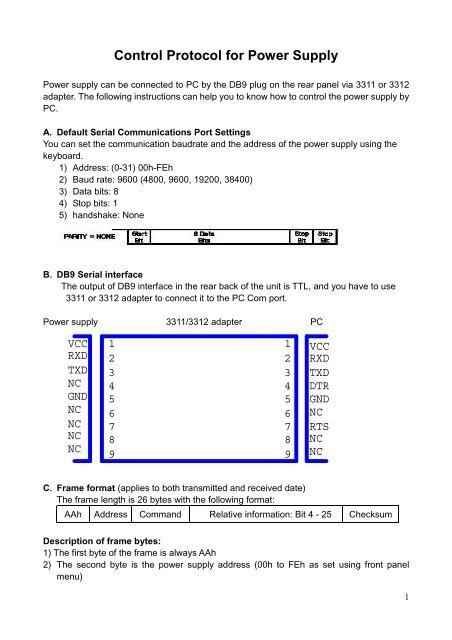
C. Frame <strong>for</strong>mat (applies to both transmitted and received date)<br />
The frame length is 26 bytes with the following <strong>for</strong>mat:<br />
1<br />
2<br />
3<br />
4<br />
5<br />
6<br />
7<br />
8<br />
9<br />
VCC<br />
RXD<br />
TXD<br />
DTR<br />
GND<br />
NC<br />
RTS<br />
NC<br />
NC<br />
AAh Address Command Relative in<strong>for</strong>mation: Bit 4 - 25 Checksum<br />
Description of frame bytes:<br />
1) The first byte of the frame is always AAh<br />
2) The second byte is the power supply address (00h to FEh as set using front panel<br />
menu)<br />
1
3) The third byte is the instrument control Command<br />
These are the possible commands:<br />
a) 80h------Set max current, max power and set-value.<br />
b) 81h------Read current, voltage, power and power supply’s state. The states include<br />
ON/OFF, over current and over power status of the power supply.<br />
c) 82h------ To control the ON/OFF state of the power supply<br />
d) 83h------Set the protection state of power supply<br />
e) 84h------Read the protection state of power supply<br />
f) 85h------ Demarcate the power command<br />
g) 86h------Return the actual output voltage to power supply<br />
h) 87h------Demarcate the current command<br />
i) 88h------Return the actual output voltage to power supply<br />
j) 89h------Set the demarcating in<strong>for</strong>mation of power supply<br />
k) 8Ah------Read the demarcating in<strong>for</strong>mation<br />
l) 8Bh------Set the serial number of power supply<br />
m) 8Ch-----Read the serial number, product model and software version of the power<br />
supply<br />
n) 12h-------Check<br />
4) If you want to control the output of the power supply by PC, you have to set the power<br />
supply at PC control state, and the command is 82h. If you want to calibrate the output<br />
of the power supply and set the calibration in<strong>for</strong>mation and serial number of the power<br />
supply, you have to set the protection status to OFF first.<br />
5) Byte 26 is the checksum obtained by adding the values of the previous 25 bytes.<br />
D. Command Descriptions<br />
1) 80h, Set power supply operating parameters and maximum limits<br />
Byte 1 Aah (frame start)<br />
Byte 2 Addresses (00h - FEh)<br />
Byte 3 80h (command)<br />
Byte 4 Low byte of the max current<br />
Byte 5 high byte of the max current<br />
Byte 6 Low byte of the low character of the Max voltage<br />
Byte 7 high byte of the low character of the Max voltage<br />
Byte 8 Low byte of the high character of the Max voltage<br />
Byte 9 high byte of the high character of the Max voltage<br />
Byte 10 Low byte of the max power<br />
2
Byte 11 high byte of the max power<br />
Byte 12 Low byte of the low character of the voltage set<br />
Byte 13 high byte of the low character of the voltage set<br />
Byte 14 Low byte of the high character of the voltage set<br />
Byte 15 high byte of the high character of the voltage set<br />
Byte 16 New address of the power supply<br />
Byte 17~25 System Reserved<br />
Byte 26 Checksum<br />
The set-values <strong>for</strong> current, power are all expressed by two bytes. The set voltage is<br />
expressed by four bytes. The low byte is sent first.<br />
For example: The current set value 3589h is specified by the following sequence:<br />
89h 35h<br />
The voltage range of 0~36V is represented by an integer in the range of 0~36000mV<br />
The current range of 0~3A is represented by an integer in the range of 0~3000mA<br />
The powere range of 0~108W is represented by an integer in the range of 0~108W<br />
2) 81h, Read the current, voltage, power value and the status of the power supply<br />
Byte 1 AAh (frame start)<br />
Byte 2 Address (00h~FEh)<br />
Byte 3 81h (Command)<br />
Byte 4 Low byte of the current<br />
Byte 5 high byte of the current<br />
Byte 6 Low byte of the low character of the voltage<br />
Byte 7 high byte of the low character of the voltage<br />
Byte 8 Low byte of the high character of the voltage<br />
Byte 9 high byte of the high character of the voltage<br />
Byte 10 Low byte of the power<br />
Byte 11 high byte of the power<br />
Byte 12 Low byte of the max current<br />
3
Byte 13 high byte of the max current<br />
Byte 14 Low byte of the low character of the Max voltage<br />
Byte 15 high byte of the low character of the Max voltage<br />
Byte 16 Low byte of the high character of the Max voltage<br />
Byte 17 high byte of the high character of the Max voltage<br />
Byte 18 Low byte of the max power<br />
Byte 19 high byte of the max power<br />
Byte 20 Low byte of the low character of the voltage set<br />
Byte 21 high byte of the low character of the voltage set<br />
Byte 22 Low byte of the high character of the voltage set<br />
Byte 23 high byte of the high character of the voltage set<br />
Byte 24 Output state of the power supply<br />
Byte 25 System reserved<br />
Byte 26 Checksum<br />
The output state of the power supply is revealed by the individual bits of byte 24:<br />
From high to low<br />
b7 b6 b5 b4 b3 b2 b1 b0<br />
b0:0=output OFF; 1=output ON<br />
b1:0=current acceptable; 1=excessive current<br />
b2:0=power acceptable; 1=excessive power<br />
b3:0=local (front panel) control; 1=remote (PC) control<br />
3) 82h, <strong>Control</strong> the ON/OFF status of the power supply<br />
Byte 1 AAh (frame start)<br />
Byte 2 Address (00h-FEh)<br />
Byte 3 82h (Command)<br />
Byte 4 The state of the power supply<br />
Byte 5~25 System reserved<br />
Byte 26 Checksum<br />
4
The desired state of the power supply is specified by the individual bits of byte 4.<br />
From high to low<br />
b7 b6 b5 b4 b3 b2 b1 b0<br />
b0: 0=output OFF; 1=output ON<br />
b1: 0=go to local mode (front panel control); 1= go to remote control (PC in control)<br />
Notes:Only under the situation of PC controlling, you can set the parameters of the power.<br />
4) 83h, Set the power calibration protection state<br />
Byte 1 AAh (frame start )<br />
Byte 2 <strong>Power</strong> Address (00h~FEh)<br />
Byte 3 83h (Command)<br />
Byte 4 <strong>Power</strong> calibration protection state<br />
Byte 5 Calibration password (0X28h)<br />
Byte 6 Calibration password (0X01h)<br />
Byte 7 to Byte 25 System reserved<br />
Byte 26 Checksum<br />
Calibration protection state is specified by one byte. The definition of each bit unit is<br />
as the following:<br />
From the high to the low<br />
b7 b6 b5 b4 b3 b2 b1 b0<br />
b0:0=protection enable; 1=protection disable<br />
5) 84h, Read the power calibration protection state<br />
Byte 1 AAh (frame start)<br />
Byte 2 <strong>Power</strong> Address (00h~FEh)<br />
Byte 3 84h (Command)<br />
Byte 4 <strong>Power</strong> calibration protection state<br />
Byte 5 to Byte 25 System reserved<br />
Byte 26 Checksum<br />
Calibration protection state is specified by one byte. The definition of each bit unit is<br />
as the following:<br />
From the high to the low<br />
b7 b6 b5 b4 b3 b2 b1 b0<br />
b0:0=protection enable; 1=protection disable<br />
5
6) 85h, Calibrate the voltage of the power supply<br />
Byte 1 AAh (frame start)<br />
Byte 2 <strong>Power</strong> Address (00h~FEh)<br />
Byte 3 85h (Command)<br />
Byte 4 Voltage calibration point (1~4)<br />
Byte 5 to Byte 25 System reserved<br />
Byte 26 Checksum<br />
7) 86h, Read the actual output voltage of the power supply<br />
Byte 1 AAh (frame start)<br />
Byte 2 <strong>Power</strong> Address (00h~FEh)<br />
Byte 3 86h (Command)<br />
Byte 4 Low byte of the low character of the actual voltage<br />
Byte 5 high byte of the low character of the actual voltage<br />
Byte 6 Low byte of the high character of the actual voltage<br />
Byte 7 high byte of the high character of the actual voltage<br />
Byte 8 to Byte 25 System reserved<br />
Byte 26 Checksum<br />
8) 87h, Calibrate the current of the power supply<br />
Byte 1 AAh (frame start)<br />
Byte 2 <strong>Power</strong> Address (00h~FEh)<br />
Byte 3 87h (Command)<br />
Byte 4 Current calibration point (1~2)<br />
Byte 5 to Byte 25 System reserved<br />
Byte 26 Checksum<br />
9) 88h, Read the actual output current of the power supply<br />
6
Byte 1 AAh (frame start)<br />
Byte 2 <strong>Power</strong> Address (00h~FEh)<br />
Byte 3 88h (Command)<br />
Byte 4 Low byte of the actual current<br />
Byte 5 high byte of the actual current<br />
Byte 5 to Byte 25 System reserved<br />
Byte 26 Checksum<br />
10) 89h, Set the calibration in<strong>for</strong>mation of the power supply<br />
Byte 1 AAh (frame start)<br />
Byte 2 <strong>Power</strong> Address (00h~FEh)<br />
Byte 3 89h (Command)<br />
Byte 4 to byte 23 Calibration in<strong>for</strong>mation (ASCII Code)<br />
Byte 24 System reserved<br />
Byte 25 System reserved<br />
Byte 26 Checksum<br />
11) 8Ah, Read the calibration in<strong>for</strong>mation of the power supply<br />
Byte 1 AAh (frame start)<br />
Byte 2 <strong>Power</strong> Address (00h~FEh)<br />
Byte 3 8Ah (Command)<br />
Byte 4 to Byte 23 Calibration In<strong>for</strong>mation (ASCII Code)<br />
Byte 24 System reserved<br />
Byte 25 System reserved<br />
Byte 26 Checksum<br />
12) 8Bh, Set the serial No of the power supply<br />
7
Byte 1 AAh (frame start)<br />
Byte 2 <strong>Power</strong> Address (00h~FEh)<br />
Byte 3 8Bh (Command)<br />
Byte 4 to Byte 23 Serial No. (ASCII Code)<br />
Byte 24 System reserved<br />
Byte 25 System reserved<br />
Byte 26 Checksum<br />
13) 8Ch, Read the serial No, product type and software version No of the power supply<br />
Byte 1 AAh (frame start)<br />
Byte 2 <strong>Power</strong> Address (00h~FEh)<br />
Byte 3 8Ch (Command)<br />
Byte 4 to Byte 9 Product serial No (ASCII Code)<br />
Byte 10 to Byte 14 Product type (ASCII Code)<br />
Byte 15 Low byte of the software version<br />
Byte 16 high byte of the software version<br />
Byte 16 to Byte 25 System reserved<br />
Byte 26 Checksum<br />
Press the button “1” on the keyboard when you are switching on the power supply,<br />
you’ll see the serial number, product type and firmware version of this unit will show<br />
on the LCD.<br />
If the product serial No is 000045, the product type is 3645A and the software version No is<br />
V2.03, the return date is as the following:<br />
A 00 30 30 30 30 30 34 35 33 36 35 41 CB 00 XX XX XX XX XX XX XX XX XX<br />
14) 12h. Return check in<strong>for</strong>mation command<br />
Byte 1 AAh (frame start)<br />
Byte 2 <strong>Power</strong> Address (00h~FEh)<br />
Byte 3 12h (Command)<br />
8
Byte 4 80h indicates correct,90h indicates wrong<br />
Byte 5 to byte 25 System reserved<br />
Byte 26 Checksum<br />
When the power receives a frame of set command, it will check this frame of command and<br />
return the relative checked result.<br />
When the power receives a frame of reading command, it will check this frame of command.<br />
If it checks correctly, it will return the relative read data. And if it checks wrongly, it will return<br />
the check command (90h).<br />
E. <strong>Power</strong> Calibration<br />
1) Structure of the system<br />
2) Procedure of calibration<br />
a) Disable the power calibration protection.<br />
AA 00 83 01 28 01 00 00 00 00 00 00 00 00 00 00 00 00 00 00 00 00 00 00 00 57<br />
b) Set load to CC mode and Load OFF<br />
c) Calibrate the first point of the voltage.<br />
AA 00 85 01 00 00 00 00 00 00 00 00 00 00 00 00 00 00 00 00 00 00 00 00 00 30<br />
9
d) Return the actual output voltage to the power supply until the output is stable.<br />
AA 00 86 XX XX 00 00 00 00 00 00 00 00 00 00 00 00 00 00 00 00 00 00 00 00 XX<br />
e) Calibrate the second point of the voltage.<br />
AA 00 85 02 00 00 00 00 00 00 00 00 00 00 00 00 00 00 00 00 00 00 00 00 00 31<br />
f) Return the actual output voltage to the power supply until the output is stable.<br />
AA 00 86 XX XX 00 00 00 00 00 00 00 00 00 00 00 00 00 00 00 00 00 00 00 00 XX<br />
g) Calibrate the third point of the voltage.<br />
AA 00 85 03 00 00 00 00 00 00 00 00 00 00 00 00 00 00 00 00 00 00 00 00 00 32<br />
h) Retun the actual output voltage to the power supply until the output is stable.<br />
AA 00 86 XX XX 00 00 00 00 00 00 00 00 00 00 00 00 00 00 00 00 00 00 00 00 XX<br />
i) Calibrate the <strong>for</strong>th point of the voltage.<br />
AA 00 85 04 00 00 00 00 00 00 00 00 00 00 00 00 00 00 00 00 00 00 00 00 00 33<br />
j) Return the actual output voltage to the power supply when the output is stable.<br />
AA 00 86 XX XX 00 00 00 00 00 00 00 00 00 00 00 00 00 00 00 00 00 00 00 00 XX<br />
k) Short-circuit the Eload.<br />
l) Calibrate the first point of the current<br />
AA 00 87 01 00 00 00 00 00 00 00 00 00 00 00 00 00 00 00 00 00 00 00 00 00 32<br />
m) Return the actual output current to the power supply until the output is stable.<br />
AA 00 88 XX XX 00 00 00 00 00 00 00 00 00 00 00 00 00 00 00 00 00 00 00 00 XX<br />
n) Calibrate the first point of the current<br />
AA 00 87 02 00 00 00 00 00 00 00 00 00 00 00 00 00 00 00 00 00 00 00 00 00 33<br />
o) Return the actual output current to the power supply until the output is stable.<br />
AA 00 88 XX XX 00 00 00 00 00 00 00 00 00 00 00 00 00 00 00 00 00 00 00 00 XX<br />
p) Enable the power calibration protection.<br />
AA 00 83 00 28 01 00 00 00 00 00 00 00 00 00 00 00 00 00 00 00 00 00 00 00 56<br />
q. The calibration is finished.<br />
10
Examples:<br />
1. Set the parameters:<br />
3000mA,36000mV,10800mW(108W) ,3000mV<br />
AA 00 80 B8 0B A0 8C 00 00 30 2A B8 0B 00 00 00 00 00 00 00 00 00 00 00 00 36<br />
2. Read the parameters:<br />
AA 00 81 00 00 00 00 00 00 00 00 00 00 00 00 00 00 00 00 00 00 00 00 00 00 2B<br />
3. Set control state:<br />
A: PC control, output ON<br />
AA 00 82 03 00 00 00 00 00 00 00 00 00 00 00 00 00 00 00 00 00 00 00 00 00 2F<br />
B: PC control, output OFF<br />
AA 00 82 02 00 00 00 00 00 00 00 00 00 00 00 00 00 00 00 00 00 00 00 00 00 2E<br />
4.Self-control<br />
AA 00 82 00 00 00 00 00 00 00 00 00 00 00 00 00 00 00 00 00 00 00 00 00 00 2C<br />
11
![[1] Signalformen am Oszilloskop bei der Offset-Kalibrierung - ELV](https://img.yumpu.com/23357707/1/184x260/1-signalformen-am-oszilloskop-bei-der-offset-kalibrierung-elv.jpg?quality=85)
![[1] PostGreSQL-Installationsanleitung - ELV](https://img.yumpu.com/22696073/1/184x260/1-postgresql-installationsanleitung-elv.jpg?quality=85)