Pressure
Pressure - 信德迈科技
Pressure - 信德迈科技
- No tags were found...

You also want an ePaper? Increase the reach of your titles
YUMPU automatically turns print PDFs into web optimized ePapers that Google loves.
Product information<br />
<strong>Pressure</strong><br />
<strong>Pressure</strong> switches · <strong>Pressure</strong> transmitters<br />
CERTIFIED<br />
ISO 9001<br />
ISO 14001<br />
DVGW<br />
TÜV
Product Overview<br />
3<br />
Contents<br />
PRESSURE SWITCHES 5<br />
Electronic pressure switches / pressure transmitters Smart Press PST/PST-R 6<br />
Applications, technical data 6<br />
Product Summary 7<br />
Definitions 8/9<br />
Electrical connection 10<br />
Switch outputs, analogue output and relay output 11<br />
Indicators and display 12<br />
Settings at user level 13<br />
Settings at expert level 14<br />
Overview of adjustable parameters 15<br />
Dimensioned drawings 16/17<br />
Mechanical pressure switches 18<br />
Technical features (sectional drawing) 18<br />
Definitions 19/20<br />
General information about explosion protection 21/23<br />
<strong>Pressure</strong> monitoring in areas at risk of explosion 24<br />
10 selection criteria 25<br />
<strong>Pressure</strong> switches – General Description 26<br />
General technical data – valid for all pressure switches 27<br />
“ZF” additional functions for pressure switches and pressure monitors 28/29<br />
Setting instructions 30<br />
<strong>Pressure</strong> switch with switching state interlock (reclosing lockout) 31<br />
Explanation of type designations – type codes 32<br />
DCM pressure switches and pressure monitors for overpressure 33<br />
VCM vacuum switches 34<br />
DNM pressure switches free of non-ferrous metal 35<br />
DNS pressure switches with stainless steel sensor system 36<br />
DDCM differential pressure switches 37<br />
DPS differential pressure switches for ventilation and air-conditioning systems 38<br />
HCD pressure and differential pressure switches for neutral gases (DVGW-tested) 39<br />
<strong>Pressure</strong> switches with 2 microswitches – technical data, switching intervals 40/41<br />
Switching schemes for ZF (additional function) 217 42<br />
Examples of use for two-stage pressure switches 43<br />
<strong>Pressure</strong> switches “of special construction” 44/45<br />
Definitions and information 44/45<br />
Safety analysis for maximum pressure monitoring 46<br />
Further observations and summary 47<br />
Standards – Directives – Component tests 48<br />
Selection according to function and application, equipment of a boiler 49<br />
DA pressure monitors and limiters for maximum pressure monitoring 50<br />
DWR pressure monitors for steam and hot water, fuel gases and liquid fuels 51/52<br />
FD safety-engineered maximum pressure limiters for liquid gas installations 53<br />
DBS series pressure monitors and pressure limiters for particularly safety-critical applications 54<br />
Safety-engineered maximum pressure monitors 55<br />
Safety-engineered minimum pressure monitors 56<br />
Features of safety-engineered pressure monitors and pressure limiters 56<br />
Mechanical pressure switches, pressure monitors for fuel gases (DVGW–tested) 57<br />
Dimensioned drawings for switch housings and pressure sensors 58/59<br />
Accessories 60<br />
EX 011, EX041 series isolating amplifiers 60/61<br />
<strong>Pressure</strong> mediators attached to pressure switches 62<br />
Siphons, NPT adapters 63<br />
Threaded joints and valve combinations 63<br />
Specifications for pressure switches and isolating amplifiers 64
4<br />
Product Overview<br />
PRESSURE SWITCHES 65<br />
Product overview 66<br />
<strong>Pressure</strong> transmitters, pressure regulators, mechanical-inductive F type series 67<br />
<strong>Pressure</strong> transmitters with terminal connection type series F... + ED1 68<br />
<strong>Pressure</strong> transmitters with plug connection type series F ... + ED3 69<br />
Technical data 70<br />
Setting, operation and testing 71/72<br />
Dimensioned drawings 73<br />
<strong>Pressure</strong> transmitters; piezoresistive, 3-conductor system SN 3 74<br />
<strong>Pressure</strong> transmitters; piezoresistive, 2-conductor system SN 2 75<br />
Operator interface / operating ranges 76<br />
Setting and testing 77<br />
Dimensioned drawings 78<br />
DPT type series differential pressure transmitters for gaseous, non-aggressive media 79<br />
AZ type series plug-in digital display 80<br />
GT type series signal separator 81<br />
AP type series programmable digital display 82<br />
Specifications for pressure transmitters 83<br />
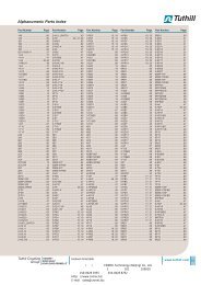
Alphabetical type index<br />
Type<br />
Page<br />
Type<br />
Page<br />
APT 82<br />
APV 82<br />
AZ 331 80<br />
DCM 33<br />
DDCM 37<br />
DGM 57<br />
DMW 63<br />
DNM 35<br />
DNS 36<br />
DPS 38<br />
DPT 79<br />
DWAM 50, 55<br />
DWAMV 50<br />
DWR 51/52<br />
EX 041 61<br />
EX 011 60<br />
Ex – DCM 33<br />
Ex – DDCM 37<br />
Ex – DGM 57<br />
Ex – DNM 35<br />
Ex – DNS 36<br />
Ex – DWR 51<br />
Ex – VCM 34<br />
Ex – VNM 34<br />
Ex – VNS 36<br />
FD 53<br />
FHBN ... 68/69<br />
FN 68/69<br />
FVN ... 68, 69<br />
GT 81<br />
HCD 39<br />
K 430 D/480 D 63<br />
MAU8 63<br />
NPT1 63<br />
PST 7<br />
PST ...-R 7<br />
SDBAM 50<br />
SN2 75<br />
SN3 74<br />
ST 12 10<br />
STA 12 10<br />
U 430 B/480 B 63<br />
VCM ... 34<br />
VCMV ... 34<br />
VKD 63<br />
VNM 34<br />
VNMV 34<br />
VNS 36<br />
ZF 28/29<br />
ZFV ... 62
<strong>Pressure</strong> switches<br />
5
6<br />
<strong>Pressure</strong> switches<br />
Electronic pressure switches / pressure transmitters PST, PST…-R / Smart Press<br />
Smart Press<br />
Electronic pressure switches / pressure transmitters<br />
PST, PST…-R<br />
PST, PST...R<br />
Applications<br />
Honeywell Fema PST and PST…-R series pressure<br />
switches are highly flexible and can be<br />
adjusted and configured in two modes, namely<br />
user mode and expert mode, and are used for<br />
fine adjustment and monitoring of system pressures<br />
in plant engineering, fluidics, process<br />
engineering and pneumatics, and for monitoring<br />
and control of pumps and compressors.<br />
Self-monitored versions are used in manufacturing<br />
lines in the automotive industry and in<br />
many areas of mechanical and special-purpose<br />
engineering. With an overall accuracy of 0.5%<br />
of full scale, these pressure switches/transmitters<br />
are also suitable for measurement monitoring<br />
in many laboratory applications.<br />
Technical data Housing and cover Polybutylene terephthalate (PBT)<br />
Ambient temperature -20 to + 60°C, from 36 V DC…50 °C<br />
Storage temperature -35 to + 80°C<br />
Medium temperature -20 to + 100°C<br />
Relative humidity<br />
0 to 95%, non-condensing<br />
Total accuracy<br />
0.5% of final value, 1…600 bar<br />
1% of final value, 250…1000 mbar<br />
Medium temperature drift 0.3% per 10 K<br />
Weight<br />
380 grams<br />
Parts in contact with medium 1.4571 + 1.4542 (high pressure)<br />
1.4571 + 1.4435 (low-pressure/flush)<br />
Process connection<br />
<strong>Pressure</strong> gauge connection G 1/2“ external thread<br />
Flush connection<br />
G 3/4” external thread<br />
Electrical connection PST versions 5-prong M12 plug, A-coded as per<br />
DIN IEC 60947-5-2<br />
PST…-R version<br />
Extra 3-prong M12 plug<br />
Protection class II as per EN 60335-1<br />
Degree of protection IP65 according to EN 60529<br />
Climate class C as per DIN EN 60654<br />
Power supply<br />
14…36 V DC, max. 100 mA<br />
EMC<br />
compatible as per EN61326/A1<br />
Electronic Outputs 2, configurable as high/low side or<br />
switch outputs<br />
push-pull switches, 14…36 V DC,<br />
(all versions)<br />
max. 250 mA<br />
Reaction time<br />
30 ms<br />
Switching differential (SP/RP) selectable via software<br />
Minimum Switching differential = ^ resolution of the display<br />
Relay outputs Contact type 1 switch-over contact (1 x UM)<br />
(PST..-R series) Min. electrical lifetime 250,000 switching cycles<br />
Switching capacity AC1 (resistive load) 1.5VA (24 VDC/60 mA, 230 VAC/6.5<br />
mA)<br />
Gold contacts AC15 (inductive load) unsuitable<br />
(AgSnO2+Au [5 μm]) Max. switching capacity 60 mA for < 5 ms<br />
Min. switching capacity<br />
50 mW (>5 V or >2 mA)<br />
Switching capacity AC1 (resistive load) 690 VA (230 V AC / 3 A)<br />
Silver contacts AC15 (inductive load) 230 VA (230 V AC / 1 A)<br />
(AgSnO2) Max. switching capacity 30 A for < 5 ms<br />
Min. switching capacity<br />
500 mW (>12 V or >10 mA)<br />
Diagnostic output Output configuration “WARN” output (plug 2) max. 20 mA,<br />
14…36 V DC<br />
Transmitter output Voltage/current 0…10 V and 4…20 mA, configurable<br />
(analogue output)<br />
in expert mode<br />
Range limitation<br />
Measuring range can be limited by up<br />
to 50% FS<br />
Step response<br />
approx. 300 ms<br />
Simulation mode System pressure simulation via pressure range<br />
Reaction test on sensor<br />
signals<br />
4 x/sec…1 x/16 sec
<strong>Pressure</strong> switches<br />
Electronic pressure switches / pressure transmitters PST, PST…-R / Smart Press<br />
7<br />
Product Summary<br />
PST = <strong>Pressure</strong> Switch +<br />
Transmitter<br />
PST…R = <strong>Pressure</strong> Switch +<br />
Transmitter + Relay<br />
01 = –1…+1 bar<br />
002 = 0–1.6 bar<br />
004 = 0–4 bar<br />
010 = 0–10 bar<br />
025 = 0–25 bar<br />
060 = 0–60 bar<br />
100 = 0–100 bar<br />
250 = 0–250 bar<br />
600 = 0–600 bar<br />
250 = 0–250 mbar<br />
400 = 0–400 mbar<br />
600 = 0–600 mbar<br />
001 = 0–1000 mbar<br />
G12S<br />
G34F<br />
= G 1/2‘‘ Standard pressure<br />
gauge version<br />
= G 3/4” quasi-flush version<br />
PST V 01 R G34F -R<br />
V<br />
M<br />
= Vacuum version<br />
= Millibar version<br />
R<br />
A<br />
= Relative pressure sensor<br />
= Absolute pressure sensor<br />
R<br />
= Relay output of electrically isolated<br />
changeover contact<br />
Ordering data<br />
Smart Press with 2 electronic switching<br />
channels + transmitteroutput<br />
Order no.<br />
<strong>Pressure</strong> in bar<br />
PSTM250RG12S 0…250 mbar<br />
PSTM400RG12S 0…400 mbar<br />
PSTM600RG12S 0…600 mbar<br />
PSTV01RG12S<br />
–1…+1<br />
PST001RG12S 0…1<br />
PST002RG12S<br />
0…1.6<br />
PST004RG12S 0…4<br />
PST010RG12S 0…10<br />
PST025RG12S 0…25<br />
PST060RG12S 0…60<br />
PST100RG12S 0…100<br />
PST250RG12S 0…250<br />
PST600RG12S 0…600<br />
PSTM250RG34F 0…250 mbar<br />
PSTM400RG34F 0…400 mbar<br />
PSTM600RG34F 0…600 mbar<br />
PSTV01RG34F<br />
–1…+1<br />
PST001RG34F 0…1<br />
PST002RG34F<br />
0…1.6<br />
PST004RG34F 0…4<br />
PST010RG34F 0…10<br />
PST025RG34F 0…25<br />
Smart Press with 2 electronic switching<br />
channels + transmitteroutput<br />
and relay output<br />
Order no.<br />
<strong>Pressure</strong> in bar<br />
PSTM250RG12S-R 0…250 mbar<br />
PSTM400RG12S-R 0…400 mbar<br />
PSTM600RG12S-R 0…600 mbar<br />
PSTV01RG12S-R –1…+1<br />
PST001RG12S-R 0…1<br />
PST002RG12S-R 0…1.6<br />
PST004RG12S-R 0…4<br />
PST010RG12S-R 0…10<br />
PST025RG12S-R 0…25<br />
PST060RG12S-R 0…60<br />
PST100RG12S-R 0…100<br />
PST250RG12S-R 0…250<br />
PST600RG12S-R 0…600<br />
PSTM250RG34F-R 0…250 mbar<br />
PSTM400RG34F-R 0…400 mbar<br />
PSTM600RG34F-R 0…600 mbar<br />
PSTV01RG34F-R –1…+1<br />
PST001RG34F-R 0…1<br />
PST002RG34F-R 0…1.6<br />
PST004RG34F-R 0…4<br />
PST010RG34F-R 0…10<br />
PST025RG34F-R 0…25<br />
Max. Bursting Dimensioned<br />
permissible pressure drawing<br />
pressure in bar Page Fig.<br />
in bar<br />
1 > = 1.6<br />
2 > = 3.2<br />
2 > = 3.2<br />
6 > = 10<br />
6 > = 10<br />
6 > = 10 16 30+31<br />
12 > = 20<br />
30 > = 50<br />
75 > = 125<br />
180 > = 300<br />
300 > = 500<br />
500 > = 1600<br />
1000 > = 1800<br />
16 32+33<br />
1 > = 1.6<br />
2 > = 3.2<br />
2 > = 3.2<br />
6 > = 10<br />
6 > = 10 17 34+35<br />
6 > = 10<br />
12 > = 20<br />
30 > = 50<br />
75 > = 125<br />
PST002AG12S 0…2<br />
PST010AG12S 0…10<br />
PST002AG12S-R 0…2<br />
PST010AG12S-R 0…10<br />
6 > = 10<br />
30 > = 50<br />
16 30+31<br />
PST002AG34F 0…2<br />
PST010AG34F 0…10<br />
PST002AG34F-R 0…2<br />
PST010AG34F-R 0…10<br />
6 > = 10<br />
30 > = 50<br />
17 32+33
8<br />
<strong>Pressure</strong> switches<br />
Electronic pressure switches / pressure transmitters PST, PST…-R / Smart Press<br />
Definitions<br />
e.g. 3.5 bar<br />
Maximum pressure monitoring<br />
<strong>Pressure</strong><br />
Maximum pressure monitoring<br />
If an output is configured as a maximum detector, the electronic pressure switch monitors a programmed<br />
upper pressure limit. A switching process is triggered as soon as the pressure exceeds<br />
this limit.<br />
e.g. 3.0 bar<br />
= active<br />
= inactive<br />
Time<br />
Minimum pressure monitoring<br />
If an output is configured as a minimum detector, the electronic pressure switch monitors a programmed<br />
lower pressure limit. A switching process is triggered as soon as the pressure falls below<br />
this limit.<br />
Minimum pressure monitoring<br />
<strong>Pressure</strong><br />
e.g. 1.0 bar<br />
e.g. 0.5 bar<br />
= active<br />
Window monitoring<br />
If an output is configured for pressure window monitoring, the electronic pressure switch monitors a<br />
programmed pressure window, i.e. the range between a defined lower limit and a defined<br />
upper limit. A switching process is triggered as soon as the pressure falls below the lower pressure<br />
limit or exceeds the upper pressure limit.<br />
Electronic pressure switch<br />
PST and PST…-R series electronic pressure switches consist of an electronic, piezoresistive pressure<br />
sensor and a downstream analyser with 2 independently programmable switching channels, an<br />
analogue output and an optionally configurable relay output.<br />
= inactive<br />
Window monitoring<br />
Time<br />
Switching differential<br />
In contrast to mechanical pressure switches, where the switching differential is essentially determined<br />
by the design, with electronic pressure switches any switching differential may be chosen. The difference<br />
between the switching point and the reset point (the switching differential) is defined at user level<br />
by entering and saving the switching and reset points via the software. The smallest definable switching<br />
differential corresponds to the display resolution.<br />
Switching point and reset point<br />
Any switching point (SP) and reset point (RP) across the entire nominal pressure range of the electronic<br />
pressure switch can be selected at user level via the software.<br />
Switching point deviation<br />
Illegal settings are automatically detected by the software. The value most recently set has priority over<br />
the value first set. If the electronic pressure switch is configured as a maximum detector, for example,<br />
the switching point (SP) must lie above the reset point (RP). If the reset point is above the<br />
switching point, or the switching point is below the reset point, no error will be displayed, but the<br />
switching points will be shifted accordingly until they are finally saved.<br />
Time Out function<br />
“Time Out” refers to the time window in which values can be entered without the display automatically<br />
reverting to pressure display mode. For all settings at user level the setting window is 1 minute.<br />
This means that if the user does not enter anything for one minute during the setting process, the unit<br />
automatically reverts to display mode and shows the current pressure in the display, disregarding any<br />
values that have been entered but not saved. However, when the unit is in setting mode at expert<br />
level, this “Time Out” function is turned off. In other words, the display (and thus the unit) remain in<br />
setting mode until the settings are saved in expert mode.
<strong>Pressure</strong> switches<br />
Electronic pressure switches / pressure transmitters PST, PST…-R / Smart Press<br />
9<br />
Escape function<br />
After entering a valid 4-digit code, the user is able to parameterise and configure the unit at user or<br />
expert level. However, the unit automatically reverts to the locked state if no adjustment activity takes<br />
place within 60 seconds. Any manipulation of the rotary/push button extends the setting time by a further<br />
60 seconds. On returning to the locked state, the word “CODE” (instead of “EXP”) appears in the<br />
corresponding screen. Once the correct code has been entered, the settings can be changed both in<br />
user mode and in expert mode.<br />
In expert mode it is also possible to change the code. While the unit is in expert mode, if values or<br />
settings are changed but not saved (with “SAVE”), the unit will remain in expert mode until a defined<br />
state is chosen with “SAVE” or “REST” (restore data). If the code is set to “0000” in expert mode and<br />
this state is saved (with “SAVE”), the unit remains in the unlocked condition. In this case the “Escape”<br />
function is disabled.<br />
Simulation<br />
To check the connection configuration or the reaction of the system to output signals, the “SIM” setting<br />
can be used to simulate the pressure for which the unit is designed. The pressure can be varied<br />
from 0-100% of the total value with a rotary switch.<br />
To show the reaction limits of the system it is also possible to set an alternating output signal with a<br />
variable pulse frequency (0 - 100% = 4x/sec …1x/16 sec). If simulation mode is not used for 30 minutes,<br />
the unit automatically reverts to display mode.<br />
Electronic slave pointer<br />
Smart Press allows you to trace a failure event back in time. The hours are counted, starting from the<br />
failure event until the readout date. This enables the system operator to determine when the failure<br />
occurred and so draw conclusions about any plant errors.<br />
Zero adjustment<br />
Zero adjustment is used to compensate any drift error of the sensor, which is liable to occur on all<br />
sensors during the lifecycle of the product. With zero adjustment, SmartPress allows you to set the<br />
display precisely to zero at zero pressure. The position of the adjustment curve is simply moved in parallel.<br />
The basic adjustment of the sensor is not changed. Zero adjustment is only possible within a<br />
range of +/– 2% of the overall pressure range. Therefore a position error, which is particularly liable to<br />
occur on sensors in the range of 0-1 bar, can easily be compensated. As the setting range is very<br />
small, it is virtually impossible for the sensor to be accidentally zeroed on pressurization.<br />
Push/pull output<br />
In expert mode the switch outputs can be configured as traditional open collector or push/pull outputs.<br />
The outputs always assume defined states (e.g.: unswitched: minus potential, switched: plus<br />
potential). If the outputs are applied to the input of a PLC, any pull-down resistors<br />
that would otherwise be necessary can be dispensed with.<br />
Adjustment dynamics<br />
The bit generator of the SmartPress has been redesigned. The time-consuming job of “scanning” with<br />
the adjusting knob has given way to a convenient, dynamic setting strategy.<br />
This allows the user to find the desired setting with just a few turns of the handwheel.
10<br />
<strong>Pressure</strong> switches<br />
Electronic pressure switches / pressure transmitters PST, PST…-R / Smart Press<br />
Electrical connection<br />
Electrical connection and contact assignment<br />
Electrical connection is via M12 plugs on the back of the unit. Depending on the version, either<br />
2 (PST) or 3 (PST…-R) M12 connector plugs are available (not supplied with the unit).<br />
Contact assignment on plug 1<br />
Pin 1: Supply voltage 14…36 VDC<br />
Pin 2: OUT 2 (output 2) open collector output<br />
Pin 3: 0 volt (ground)<br />
Pin 4: OUT 1 (output 1) open collector output<br />
Pin 5: Serial interface (locked for calibration)<br />
Special characteristic of open collector outputs:<br />
Depending on the design, the output voltage at open collector outputs can be up to 2.5 V lower than<br />
the applied supply voltage.<br />
Example: Supply voltage 14 V… output voltage OUT 1 approx. 11.5 V.<br />
Contact assignment on plug 2<br />
All versions of series PST and PST…-R are also equipped with an A-coded M 12 plug.<br />
Pin 1: Supply voltage 14…36 VDC<br />
Pin 2: WARN (warning output max. 20 mA)<br />
Pin 3: 0 V (ground)<br />
Pin 4: Analogue output AOUT<br />
Pin 5: Serial interface (for factory calibration only)<br />
Units of the PST series can be powered both via plug 1 and via plug 2. If the PST is used purely as a<br />
transmitter, only one connection via plug 2 is needed, because the supply voltage can be connected<br />
here too (see “Contact assignment on plug 1”).<br />
Contact assignment on plug 3<br />
All versions of series PST…R are also equipped with a B-coded M 12 plug.<br />
Suitable cable sockets should be ordered at the same time for the electrical connection.<br />
Optional accessories<br />
Cable socket<br />
5-pole ST12-5-G straight version<br />
5-pole ST12-5-A right-angle version<br />
4-pole ST12-4-G straight version with 2 m cable<br />
4-pole ST12-4-A right-angle version with 2 m cable<br />
Plug protection cap<br />
IP67 STA12<br />
NB – For IP65 special plug protection cap STA12 is required<br />
Observance of IP65 water and dust proofing requires the secure sealing of electrical connections not<br />
closed with plugs.<br />
The soft rubber dust caps fitted for shipping do not fulfil this requirement. A reliable seal can only be<br />
achieved by the STA12 protection cap.
<strong>Pressure</strong> switches<br />
Electronic pressure switches / pressure transmitters PST, PST…-R / Smart Press<br />
11<br />
Switch outputs<br />
Switch output OUT1 and OUT2:<br />
The switch outputs can be configured via the software (at expert level) both as normally closed / normally<br />
open, and as high-side and low-side switching.<br />
low-side switching<br />
high-side switching<br />
· In normally closed configuration, the selected voltage potential (ground or supply voltage) occurs<br />
at the output in the unswitched state.<br />
· In normally open configuration, the selected voltage potential (ground or supply voltage) occurs at<br />
the output in the switched state.<br />
· In the low-side switching configuration, the outputs switch the voltage potential 0V (ground) with<br />
respect to a consumer connected to OUT1 or OUT2.<br />
· In the high-side switching configuration, the outputs switch the supply voltage potential (minus<br />
approx. 2V) with respect to a consumer connected to OUT1 or OUT2.<br />
If the power supplies of the pressure switch and connected load are independent of one<br />
another, the following must be taken into account: The potential difference between OC output<br />
and ground and OC output and supply voltage must not exceed 36 VDC. If the unit is<br />
configured for low-side switching, the external supply voltage must have the same ground<br />
reference as the unit itself. If the unit is defined as high-side switching, the external supply<br />
voltage must be linked to the supply voltage of the unit. It is important to note that the voltage<br />
drop in the through-connected state can be as much as 2 V. The maximum permitted<br />
current at the OC is 250 mA per switch output (OUT1, OUT2). A maximum switching current<br />
of 250 mA may flow through each channel.<br />
The switching channels are short-circuit-proof and they are monitored for current and temperature.<br />
Where current limiting is used and on overheating, both LEDs light up red (WARN function).<br />
The freely configurable outputs can connect both the supply voltage (+ potential) itself and the ground<br />
(– potential) of the supply voltage to the output. If plus potential exists at the output, ground minus<br />
potential occurs after switching over.<br />
If ground minus potential exists at the output, plus potential occurs after switching over.<br />
High-side switching push/pull outputs<br />
Advantage: The output behaves like a mechanical changeover contact which emits either plus or<br />
minus potential. In other words, the open output is never electrically undefined, as is the case with an<br />
open collector output. Pull-up resistors are therefore unnecessary.<br />
Analogue output and relay output<br />
plug 3<br />
Analogue output AOUT:<br />
The analogue output (AOUT) is available in versions PST and PST…-R. In expert mode it is configurable<br />
both as a 0-10 V/10-0 V, and as a 4–20 mA/20–4 mA output. The unit is supplied with the output<br />
configured for 0-10 V. The input impedance of the connected consumer must not exceed 500<br />
ohms.<br />
Relay output REL:<br />
The relay output is available in version PST…-R. In expert mode the analogue output can be coupled<br />
via the software with output 1 (OUT1) and output 2 (OUT2), and with the WARN function. This means<br />
that the user can choose a potential-free output for these 3 important functions. The changeover contact<br />
of the relay is designed for a maximum resistive load of 4 A and an inductive load of 200 VA. At<br />
the lower end the 5 μ gold-plated silver contacts are designed for a minimum load of 50 mW. (5 V at<br />
10 mA).<br />
It should always be remembered that after a one-off maximum load, use at minimum load is<br />
no longer possible.
12<br />
<strong>Pressure</strong> switches<br />
Electronic pressure switches / pressure transmitters PST, PST…-R / Smart Press<br />
Indicators and display<br />
The indicators in the display<br />
have the following meanings:<br />
ATT<br />
EXPERT<br />
WARN<br />
WIN<br />
Attenuation (for setting a filter)<br />
Expert mode (allows the user to<br />
configure the unit, e.g. as maximum<br />
detector or minimum detector<br />
or for window monitoring)<br />
Warning function / alarm<br />
Window monitoring (for monitoring<br />
a pressure window to detect<br />
exceeding or falling below a<br />
selected pressure window)<br />
OUT1 Switch output OC 1<br />
OUT2 Switch output OC 2<br />
SP<br />
RP<br />
AOUT<br />
ZERO<br />
FSO<br />
INV<br />
Switching point<br />
Reset point<br />
Switch contact configured as normally<br />
open<br />
Switch contact configured as normally<br />
closed<br />
Analogue output (if the current<br />
pressure is outside the currently<br />
set range, the “AOUT” symbol is<br />
not visible).<br />
Zero point display for the analogue<br />
output or display symbol if output<br />
1 or output 2 defined as low-side<br />
switching (unit switches power<br />
supply plus to the output).<br />
Combined with “FSO” in the<br />
switch configuration menu as indicator<br />
for the push/pull function.<br />
Upper limit of the selected analogue<br />
display range or display<br />
symbol if output 1 or 2 defined as<br />
high-side switching. (unit switches<br />
power supply minus to the output).<br />
Combined with “ZERO” in the<br />
switch configuration menu as indicator<br />
for the push/pull function.<br />
Inversion of the analogue signal<br />
(i.e. “INV” appears if, instead of a<br />
standard analogue signal 0…10 V<br />
or 4…20 mA, the analogue signal<br />
output is set to 10…0 V or<br />
20…4 mA).<br />
Display<br />
The unit has a 4-place digital display with 3 decimal points and a minus sign. There are also other<br />
symbols for the different settings and configurations.<br />
The display also includes a bar graph. This is at the top of the display and consists of a row of separately<br />
addressable individual segments with arrow symbols at either end.<br />
As soon as the unit is powered up, all symbols appear on the display for 1 second as a test and the<br />
two LEDs light up briefly. The unit then goes into display mode, showing the current system pressure<br />
and the selected unit (bar, PSI or Pa). In addition the pressure trend (falling or rising) is indicated by an<br />
arrow at the left (falling) or right (rising) end. The “AOUT” indicator tells the user that the pressure is<br />
currently in the predefined pressure range for the analogue signal.<br />
Meaning of LED colours<br />
LED status<br />
Meaning<br />
LED 1 LED 2 Output 1 Output 2<br />
lit lit Status Status<br />
green green inactive inactive<br />
green orange inactive active<br />
orange green active inactive<br />
orange orange active active<br />
red red SP/RP implausible<br />
red red error<br />
Status LEDs<br />
The current status of the switch outputs is displayed by 2 LEDs located beneath the display (LED 1 and<br />
LED 2). The two 3-colour LEDs indicate the switching status of the corresponding output and the<br />
warning function.<br />
· Orange: the output is ACTIVE<br />
· Green: the output is INACTIVE (if defined as WARN output, likewise INACTIVE)<br />
· During input of the switching points, only the LED of the switching channel currently being modified<br />
is active. When switching points are entered, if an implausible entry is made for the maximum detector,<br />
e. g. SP < RP, the relevant channel LED lights up red.<br />
· Both status LEDs light up red as soon as a WARN state occurs (e. g. electronics faulty and unit overheating).<br />
Warning with both LEDs RED and WARN output active<br />
Display indication<br />
- on sensor failure -***1<br />
- under-voltage -**1*<br />
- under-temperature -*1**<br />
- over-temperature -*2**<br />
Display indication<br />
- overload output 1 -1***<br />
- overload output 2 -2***<br />
- overload output 1 and 2 -3***
<strong>Pressure</strong> switches<br />
Electronic pressure switches / pressure transmitters PST, PST…-R / Smart Press<br />
13<br />
Settings at user level<br />
Switch output OUT 1 and OUT 2<br />
At user level, the switching point (SP) and reset point (RP) can be set across the entire nominal pressure<br />
range.<br />
When the DIG (digital incremental sensor) is turned by one notch in the clockwise direction, the symbol<br />
“OUT 1” and “SP” appears. When the DIG is pressed, the EDIT “symbol” appears.<br />
After that, any switching point can be selected by turning the DIG clockwise or anticlockwise. When<br />
you press the DIG again, “SAVE” is displayed. Press the DIG again to confirm. The chosen switching<br />
point is now permanently saved.<br />
Turn it clockwise again to display the reset point (RP) symbol. The reset point (RP) is set in the same<br />
way as the switching point (SP).<br />
Analogue output (AOUT)<br />
Turning the DIG clockwise again opens the analogue output (AOUT) window. The screen displays the<br />
lower pressure value set (AOUT ZERO). Press the DIG to enter “EDIT” mode and then “SAVE” to save<br />
the lower reference value permanently.<br />
Turn the DIG again to set “AOUT” “FSO”. Here you can alter the upper reference value. The pressure<br />
value can be changed in the way described above.<br />
<strong>Pressure</strong><br />
without filter<br />
setting<br />
with filter<br />
setting<br />
Time<br />
Filter setting (attenuation)<br />
To make the pressure switch insensitive to pressure peaks and to avoid distorting the measured value<br />
due to pressure peaks, a filter value of 0…95% can be set. After setting the switching points of<br />
OUT 2, turn the DIG again to open the “ATT” window. After pressing the DIG the user can change the<br />
value in edit mode (EDIT) or turn the filter off completely (OFF). Save the selected filter value with<br />
“SAVE”. It is now permanently stored in the memory. The currently measured pressure is compared<br />
with the pressure measured previously. The currently measured pressure is then attenuated depending<br />
on the selected degree of filtering. This attenuation affects all outputs, i. e. all open collector outputs<br />
and relay outputs as well as the analogue output, as the attenuation has a direct influence on the<br />
incoming sensor signal. The previously measured pressure and the currently measured pressure (internally<br />
offset against each other) always produce a weight of 100%. The filter attenuation (effect) can be<br />
mathematically expressed as follows:<br />
R[x] = M[x] * (100% - F) + R[x - 1] * F<br />
where:<br />
“F” is the selected attenuation in %,<br />
“M[x]” is the measured value as a function of a defined time “x”,<br />
“R[x - 1]” is the previously displayed and output (calculated) measured value “x - 1”, and<br />
“R[x]” is the displayed and output (calculated) measured value in the time “x”.<br />
Electronic slave pointer<br />
Before you exit user mode, the Smart Press shows the extreme states in the past by means of<br />
right/left bar graph arrows and maximum values in the vacuum/overpressure range. Press DIG<br />
once to enter “EDIT” mode and turn the knob to see how much time has passed since the event<br />
occurred.
14<br />
<strong>Pressure</strong> switches<br />
Electronic pressure switches / pressure transmitters PST, PST…-R / Smart Press<br />
Settings at expert level<br />
Configuration of OUT 1 and OUT 2<br />
The last menu item in user mode (EXP) allows you to enter expert mode (after entering a code if necessary).<br />
The screen shows the configuration of OUT 1 (e.g. as WIN monitor for pressure window monitoring).<br />
Press the DIG to enter edit mode (EDIT). Output 1 can be configured as a minimum detector<br />
(left arrow), maximum detector (right arrow) or for pressure window monitoring (WIN) and as a<br />
push/pull output. Press to confirm your selection and open the function screen (FCT 1) of output 1.<br />
Press to enter edit mode (EDIT) and configure output 1 as normally open (NO), normally closed (NC),<br />
high-side or low-side switching or as a push/pull output.<br />
OUT 2 is configured in the same sequence, but note than output 2 can also be configured as a<br />
WARN output.<br />
Configuration of analogue output (AOUT)<br />
Turn the DIG clockwise again to open the configuration menu (AOUT). The screen shows either FCTA<br />
(current output) or FCTV (voltage output). In EDIT mode the analogue output can be configured as<br />
current or voltage output, or inverted.<br />
Allocation of relay contact (on PST…-R versions only)<br />
Turn the DIG clockwise again to enter the relay output configuration mode (REL). Press to switch to<br />
EDIT mode. Turn to apply the relay function to OUT 1, OUT 2 or WARN. The OC outputs are not<br />
affected by this. That is to say, the relay function should always be regarded as parallel to the corresponding<br />
output.<br />
Setting pressure units to bar, Pascal or PSI<br />
Turn the DIG clockwise again to enter the “UNIT” menu. Press and turn to select and confirm the<br />
desired pressure unit.<br />
Setting the display background lighting<br />
Select the menu option LED+ at expert level and “EDIT”, then choose LED+ (permanently lit) or<br />
LED– (switching off automatically).<br />
Simulation mode<br />
Smart Press allows you to simulate various system states for checking connections and functions.<br />
Select menu option SIM1 to take the system pressure through 0-100% according to the sensor specification.<br />
Selected switching points and the analogue output can be checked during this process.<br />
The menu option SIM2 allows you to initiate an alternating square wave signal with a variable pulse frequency.<br />
In this way you can test the system’s ability to react to sensor signals. If the display shows<br />
SIM--, simulation mode is turned off.<br />
Setting a four-digit locking code<br />
Turn the DIG clockwise again to enter the “CODE” menu. Press to enter EDIT mode, where you can<br />
enter and confirm a four-digit code between 0001 and 9999. 0000 is not a code.<br />
Exiting expert level via the EXIT menu<br />
Turn the DIG clockwise again to enter the “EXIT” menu. Press to go directly to display mode or to the<br />
SAVE menu (if any value has been modified). Here you can either confirm the new state with SAVE, or<br />
go back to the previous state (which existed before the modification) with REST (Restore).
<strong>Pressure</strong> switches<br />
Electronic pressure switches / pressure transmitters PST, PST…-R / Smart Press<br />
15<br />
Overview of adjustable parameters<br />
Activity / Situation Indications in LCD display Parameters modifiable in<br />
Symbols Digital values/text User mode Expert mode<br />
Current pressure is displayed*<br />
Current pressure , relevant unit relevant digital value – –<br />
Output OUT 1 active OUT 1 – – –<br />
Output OUT 2 active OUT 2 – – –<br />
AOUT (pressure between ZERO and FSO) AOUT – – –<br />
Rising pressure – – –<br />
Falling pressure – – –<br />
Alarm (sensor, power supply etc.) WARN ***1, **1* etc. No No<br />
Parameterisation of outputs OUT 1 (and OUT 2)*<br />
SP , OUT1 (OUT2), SP digital value Yes No<br />
RP , OUT1 (OUT2), RP digital value Yes No<br />
1. Window (WIN) setting , OUT1 (OUT2), SP digital value Yes No<br />
2. Window (WIN) setting , OUT1 (OUT2), RP digital value Yes No<br />
Configuration of outputs OUT 1 (and OUT 2)<br />
Maximum pressure monitor (SP>RP) EXPERT, SP, RP, OUT1 (OUT2) No Yes<br />
Minimum pressure monitor (SP
16<br />
<strong>Pressure</strong> switches<br />
Electronic pressure switches / pressure transmitters PST, PST…-R / Smart Press<br />
Dimensioned drawings<br />
30 31<br />
32 33
<strong>Pressure</strong> switches<br />
Electronic pressure switches / pressure transmitters PST, PST…-R / Smart Press<br />
17<br />
34 35
18<br />
<strong>Pressure</strong> switches<br />
Mechanical pressure switches<br />
Mechanical pressure switches<br />
Technical features / Advantages<br />
Diecast aluminium housing<br />
IP 54 or IP 65<br />
version also available<br />
Wall mounting<br />
or directly on the pressure line<br />
Switching element (microswitch)<br />
Lead sealable setpoint adjustment<br />
Setting spindle locking element<br />
Terminal connection<br />
or plug connection to<br />
DIN 43 650 Form A<br />
Stainless steel sensor housing<br />
Stainless steel bellows<br />
with internal stop<br />
<strong>Pressure</strong> connection<br />
G 1/2“ external<br />
G 1/4” internal<br />
Centring pin
<strong>Pressure</strong> switches<br />
Mechanical pressure switches<br />
19<br />
Definitions<br />
<strong>Pressure</strong> data<br />
Overpressure<br />
Vacuum<br />
Absolute pressure<br />
<strong>Pressure</strong> over atmospheric pressure. The reference point is atmospheric pressure.<br />
<strong>Pressure</strong> under atmospheric pressure. The reference point is atmospheric<br />
pressure.<br />
<strong>Pressure</strong> relative to absolute vacuum.<br />
Differential pressure Difference in pressure between 2 pressure measuring points.<br />
Relative pressure<br />
Overpressure or vacuum relative to atmospheric pressure.<br />
<strong>Pressure</strong> data in all FEMA documents refer to relative pressure.<br />
That is to say, they concern pressure differentials relative to atmospheric pressure. Overpressures have<br />
a positive sign, vacuums a negative sign.<br />
Permissible bursting pressure (maximum permissible pressure)<br />
The maximum working pressure is defined as the upper limit at which the operation, switching reliability<br />
and water tightness are in no way impaired (for values see Product Summary).<br />
Bursting pressure (test pressure)<br />
Type-tested products undergo a pressure test certified by TÜV affirming that the bursting pressure<br />
reaches at least the values mentioned in the Product Summary. During the pressure tests the measuring<br />
bellows are permanently deformed, but the pressurized parts do not leak or burst. The bursting pressure<br />
is usually a multiple of the permissible working pressure.<br />
Setting range<br />
<strong>Pressure</strong> range in which the cutoff pressure can be set with the setting spindle.<br />
<strong>Pressure</strong> units<br />
Unit bar mbar Pa kPa MPa (psi) Ib/m 2<br />
1 bar 1 1000 10 5 100 0.1 14,5<br />
1 mbar 0.001 1 100 0.1 10 -4 0.0145<br />
1 Pa 10 -5 0.01 1 0.001 10 -6 1.45 · 10 -4<br />
1 kPa 0.01 10 1000 1 0.001 0.145<br />
1 MPa 10 10 4 10 6 1000 1 145<br />
1 psi 0.069 68.94 6894 6.894 0.00689 1<br />
In FEMA documents pressures are stated in bar or mbar.<br />
<strong>Pressure</strong> data for a pressure<br />
switch based on the example of<br />
DWR 625:<br />
Setting range: 0.5–6 bar<br />
Perm. working pressure: 20 bar<br />
Bursting pressure: >100 bar<br />
Important:<br />
All pressure data are overpressures or vacuums relative to atmospheric pressure.<br />
Overpressures have a positive sign, vacuums a negative sign.
20<br />
<strong>Pressure</strong> switches<br />
Mechanical pressure switches<br />
Definitions<br />
Maximum pressure monitoring<br />
RSP =SP –xd<br />
Minimum pressure monitoring<br />
RSP =SP+xd<br />
Switching differential<br />
The switching differential (hysteresis) is the difference in pressure between the switching point (SP)<br />
and the reset point (RSP) of a pressure switch. Switching differential tolerances occur due to tolerances<br />
in the microswitches, springs and pressure bellows. Therefore the data in the Product<br />
Summaries are always average values. In the case of limiter functions the switching differential has no<br />
significance, as one is only interested in the switching point at which cutoff occurs, not the reset point.<br />
For a controller function, i.e. in the case of pressure switches used to switch a burner, pump etc.<br />
on and off, a pressure switch with an adjustable switching differential should be chosen.<br />
The switching frequency of the burner or pump can be varied by changing the switching differential.<br />
Adjustable switching differential / Calibration<br />
In the case of pressure switches with adjustable switching differential, the hysteresis can be set within<br />
the specified limits. The switching point (SP) and reset point (RSP) are precisely definable. When setting<br />
the pressure switch, the switching differential situation and the type of factory calibration must be<br />
taken into account. Some pressure switches (e.g. minimum pressure monitors of the DCM series) are<br />
calibrated under “falling” pressure, i.e. switching under falling pressure takes place at the scale value<br />
with the switching differential lying above it. The device switches back at scale value + switching differential.<br />
If the pressure switch is calibrated under rising pressure, switching takes place at the scale<br />
value and the device switches back at scale value — switching differential (see direction of action).<br />
The calibration method is indicated in the data sheets.<br />
Direction of action<br />
In principle, any pressure switch can be used for both maximum pressure and minimum pressure<br />
monitoring. This excludes pressure limiters, whose direction of action (maximum or minimum) is predefined.<br />
The only thing to remember is that the scale reading may deviate by the amount of the switching<br />
differential. See example at bottom left: The scale value is 2.8 bar.<br />
Maximum pressure monitoring<br />
With rising pressure, switching takes place once the preset switching pressure is reached (SP). The<br />
reset point (RP) is lower by the amount of the switching differential.<br />
Minimum pressure monitoring<br />
With falling pressure, switching takes place once the preset switching pressure is reached (SP).<br />
The reset point (RP) is higher by the amount of the switching differential.<br />
Direction of action in vacuum range<br />
It is particularly important to define the direction of action in the vacuum range.<br />
Rising does not mean a rising vacuum, but rising pressure (from the point of view of absolute “0”).<br />
“Falling” pressure means a rising vacuum.<br />
Example: Vacuum switch set to –0.6 bar falling means: Switching (SP) takes place under falling pressure<br />
(rising vacuum) at –0.6 bar. The reset point is higher by the amount of the switching differential<br />
(e.g. at –0.55 bar).<br />
Setting a pressure switch<br />
To define the switching point of a pressure switch exactly, in addition to the pressure it is also necessary<br />
to determine the direction of action. “Rising” means that switching takes place at the set value<br />
when the pressure rises.<br />
The reset point is then lower by the amount of the switching differential. “Falling” means exactly the<br />
opposite.<br />
Please note when specifying the setting of a pressure switch:<br />
In addition to the switching point it is also necessary to specify the direction of action (falling or rising).<br />
Example for selection of a pressure switch:<br />
A pump is to be turned on at 2.8 bar and off again at 4.2 bar.<br />
Chosen type: DCM6-203 according to data sheet DCM. Setting: Scale pointer to 2.8 bar (lower<br />
switching point). Switching differential to 1.4 bar (set according to pressure gauge).<br />
Cutoff point: 2.8 bar +1.4 bar = 4.2 bar.
<strong>Pressure</strong> switches<br />
Mechanical pressure switches<br />
21<br />
General information about<br />
explosion protection<br />
Basic principle<br />
The basic principle of explosion protection is that:<br />
a) combustible materials (gas, vapour, mist or dust) in dangerous quantities<br />
b) air (or oxygen)<br />
c) ignition sources<br />
must not occur in the same place.<br />
The permanent or temporary occurrence of explosive mixtures as per a) and b) is often unavoidable,<br />
therefore when operating electrical installations care must be taken to ensure that no ignition sources<br />
can occur.<br />
With this in mind, the CENELEC technical committee has adopted the following European standards<br />
which are recognized in all EU member states.<br />
· General requirements EN 50 014 · <strong>Pressure</strong> resistant encapsulation “d” EN 50 018<br />
· Oil encapsulation “o” EN 50 015 · Increased safety “e” EN 50 019<br />
· Overpressure encapsulation “p” EN 50 016 · Intrinsic safety “i” EN 50 020<br />
· Sand encapsulation “q” EN 50 017 · Cast encapsulation “m” EN 50 028<br />
The guidelines relevant to FEMA products – besides the “General Requirements EN 50 014” – are<br />
“<strong>Pressure</strong> resistant encapsulation d” and “Intrinsic safety i”.<br />
In addition, all explosion protection guidelines issued up to the present time have been combined into<br />
a single European Ex-Protection Directive 94/9EC. The aim of this new harmonized directive is to bring<br />
the explosion protection regulations of European member states into line with one another and eliminate<br />
barriers to trade between partner states. The new Directive 94/9EC (ATEX 100a), which came<br />
into force on 1 July 2003, replaces all previous directives.<br />
All FEMA ex-pressure switches and ex-thermostats meet the requirements of the new European Ex-<br />
Protection Directive 94/9EC (ATEX 100a).<br />
EEx-d<br />
<strong>Pressure</strong> resistant encapsulation “d”<br />
Switching elements and other electrical function units capable of igniting an explosive mixture are cast<br />
in a housing capable of withstanding the explosive pressure caused by an explosion indoors and preventing<br />
transmission to the surrounding atmosphere.<br />
EEx-i<br />
Intrinsic safety “i”<br />
The equipment used in the area at risk of explosion contains only intrinsically safe electric circuits. An<br />
electric circuit is only intrinsically safe if the quantity of energy is so small that no spark or thermal<br />
effect can occur.<br />
The term “simple electrical equipment”<br />
In view of the use of simple microswitches without additional capacitance or inductance generating<br />
components, our pressure switches and thermostats designed for protection type Ex-i fall in the category<br />
of “simple electrical equipment”. These are not subject to testing or certification requirements<br />
within the meaning of Directive 94/9EC. The units may only be used in conjunction with ATEX-tested<br />
isolating amplifiers in areas at risk of explosion. We equip all units which are explicitly designed for<br />
such use with microswitches having gold contacts, a grounding screw and — for ease of identification<br />
— a blue cable entry.
22<br />
<strong>Pressure</strong> switches<br />
Mechanical pressure switches<br />
General information about<br />
explosion protection<br />
Zone classification<br />
Explosion risk areas are grouped into zones according to the likelihood of a dangerous explosive<br />
atmosphere according to EN 1127-1 occurring.<br />
When assessing the explosion hazard, i.e. when identifying explosion risk areas, the “Guidelines for<br />
the Avoidance of Danger due to Explosive Atmospheres with Examples (ExRL)” of the German<br />
Insurance Association for the Chemical Industry [Berufsgenossenschaft Chemie] must be taken into<br />
account.<br />
If the situation concerns a special case or if doubts exist as to the definition of explosion risk areas, the<br />
matter shall be decided by the supervisory authorities (Trade Supervisory Office [Gewerbeaufsichtsamt],<br />
where applicable with the assistance of the Insurance Association or the Technical Control<br />
Boards [Technische Überwachungsvereine]).<br />
In Zones 0 (20) and 1 (21), only electrical equipment for which a type test certificate has been issued<br />
by a recognized testing agency may be used. In Zone 0 (20), however, only equipment expressly<br />
authorized for that zone may be used. Equipment approved for use in Zones 0 (20) and 1 (21) may<br />
also be used in Zone 2 (22). Under the new European Directive 94/9 EC (ATEX 100a), a distinction is<br />
made between gas atmospheres and dust atmospheres. This results in the following zone classifications:<br />
Gas<br />
Dust<br />
Zone 0<br />
Zone 0 (gas) is a place in which a dangerous explosive<br />
atmosphere is present continuously or for long periods. This<br />
normally includes only the interior of containers or the interior<br />
of apparatus (evaporators, reaction vessels etc.), if the conditions<br />
of Zone 0 are fulfilled. Continuous danger > 1000<br />
hours/year.<br />
Zone 1 occasionally Zone 1 (gas) is a place in which a dangerous explosive<br />
atmosphere can be expected to occur occasionally in normal<br />
operation. This may include the immediate vicinity of Zone 0.<br />
Occasional danger = 10 to 1000 hours/year.<br />
Zone 2<br />
Zone 20<br />
continuously or<br />
for long periods<br />
seldom and for<br />
short periods<br />
continuously or<br />
for long periods<br />
Zone 2 (gas) is a place in which a dangerous explosive<br />
atmosphere can be expected to occur only rarely and then<br />
only for short periods. This may include areas surrounding<br />
Zones 0 and/or 1. Danger only under abnormal operating conditions<br />
< 10 hours/year.<br />
Zone 20 (dust) is a place in which a dangerous explosive<br />
atmosphere in the form of a cloud of dust in air is present<br />
continuously or for long periods, and in which dust deposits of<br />
unknown or excessive thickness may be formed. Dust<br />
deposits on their own do not form a Zone 20. Continuous<br />
danger > 1000 hours/year.<br />
Zone 21 occasionally Zone 21 (dust) is a place in which a dangerous explosive<br />
atmosphere in the form of a cloud of dust in air may occasionally<br />
occur in normal operation, and in which deposits or layers<br />
of inflammable dust may generally be present. This may also<br />
include the immediate vicinity of Zone 20. Occasional danger<br />
= 10 to 1000 hours/year.<br />
Zone 22<br />
seldom and for<br />
short periods<br />
Zone 22 (dust ) is a place in which a dangerous explosive<br />
atmosphere may be expected to occur only rarely and then<br />
only for short periods. This may include areas in the vicinity of<br />
Zones 20 and 21. Danger only under abnormal operating conditions<br />
< 10 hours/year.
<strong>Pressure</strong> switches<br />
Mechanical pressure switches<br />
23<br />
General information about<br />
explosion protection<br />
Explosion group<br />
The requirements for explosion-protected equipment depend on the gases and/or vapours present on<br />
the equipment and on the dusts lying on, adhering to and/or surrounding the equipment. This affects<br />
the gap dimensions required for pressure-proof encapsulation and, in the case of intrinsically safe circuits,<br />
the maximum permitted current and voltage values. Gases, vapours and dusts are therefore<br />
subdivided into various explosion groups.<br />
The danger of the gases rises from explosion group IIA to IIC. The requirements for electrical equipment<br />
in these explosion groups increase accordingly. Electrical equipment approved for IIC may also<br />
be used for all other explosion groups.<br />
Temperature class<br />
The maximum surface temperature of an item of equipment must always be lower than the ignition<br />
temperature of the gas, vapour or dust mixture. The temperature class is therefore a measure of the<br />
maximum surface temperature of an item of equipment.<br />
Temperature class Ignition temperature °C Maximum surface temperature<br />
°C<br />
T1 > 450 450<br />
T2 > 300 300<br />
T3 > 200 200<br />
T4 > 135 135<br />
T5 > 100 100<br />
T6 > 85 85<br />
Identification of explosion-protected electrical equipment<br />
In addition to normal data (manufacturer, type, serial number, electrical data), data relating to the explosion<br />
protection must be included in the identification.<br />
Under the new Directive 94/9EC (ATEX 95), based on IEC recommendations, the following identification<br />
is required:<br />
For example: II G D EEx de IIC T6 IP65 T 80 °C<br />
Ex-protection symbol<br />
Device group II<br />
Approved for gas<br />
Approved for dust<br />
Symbol for equipment built in<br />
accordance with European standards<br />
Explosion protection identifier<br />
Explosion group<br />
Temperature class<br />
IP protection class<br />
Approved maximum temperature
24<br />
<strong>Pressure</strong> switches<br />
Mechanical pressure switches<br />
<strong>Pressure</strong> monitoring in explosion risk<br />
areas Zone 1, 2 and 21, 22<br />
Specially equipped pressure switches can also be used in explosion risk areas Zone 1, 2 and 21,<br />
22. The following alternatives are possible:<br />
1. <strong>Pressure</strong>-proof encapsulated switching device,<br />
explosion protection EEx de IIC T6, PTB 02 ATEX 1121<br />
The pressure switch with pressure-proof encapsulation can be used directly in the explosion risk area<br />
(Zone 1 and 2 or 21 and 22). The maximum switching voltage, switching capacity and ambient temperature<br />
must be taken into account and the rules for installation in the explosion risk area must be<br />
observed. All pressure switches may be equipped with explosion-proof switching devices. However,<br />
special circuits and designs with an adjustable switching differential or internal interlock (reclosing lockout)<br />
are not permitted.<br />
2. EEx-i pressure switches<br />
All pressure switches of normal design can be used in explosion risk areas Zone 1 and 2 or 21 and<br />
22, if they are integrated into an “intrinsically safe control current circuit”. Intrinsic safety is based on<br />
the principle that the control current circuit in the explosion risk area carries only a small quantity of<br />
energy which is not capable of generating an ignitable spark.<br />
Isolating amplifiers, e.g. type Ex 011 or Ex 041, must be tested by the Physikalisch-Technische<br />
Bundesanstalt (PTB) and approved for use in explosion risk areas. Isolating amplifiers must always be<br />
installed outside the explosion risk zone.<br />
<strong>Pressure</strong> switches designed for EEx-ia installations may be provided with blue connection terminals<br />
and cable entries. In view of the low voltages and currents carried via the contacts of the microswitches,<br />
gold-plates contacts are recommended (additional function ZF 513).<br />
3. <strong>Pressure</strong> switches with microswitch and resistor combination for short-circuit and line<br />
break monitoring (see DBS series)<br />
A combination of a pressure switch with mechanical microswitch connected to a 1.5 kOhm series<br />
resistor and a safety-engineered isolating amplifier (type Ex 041) may also be used in explosion risk<br />
zones 1, 2 and 21, 22 (explosion protection EEx-ia).<br />
The safety-engineered isolating amplifier produces a separate intrinsically safe control current circuit<br />
and at the same time monitors the supply conductors between the isolating amplifier and the pressure<br />
switch for short-circuit and line break. In this regard, see also the section on pressure limiters for safety-critical<br />
applications and data sheet Ex 041.<br />
<strong>Pressure</strong> monitoring in explosion risk areas Zone 1 (21) and 2 (22)<br />
Ex-D…<br />
<strong>Pressure</strong>-proof encapsulated<br />
Explosion protection: EEx de<br />
IIC T6 PTB approval for the<br />
complete switching device.<br />
Switching capacity at 250 V/3<br />
A. The pressure switch can be<br />
installed within the Ex-Zone.<br />
D…-513 + Ex 011<br />
Intrinsically safe<br />
Explosion protection: EEx-ia<br />
PTB approval for isolating<br />
amplifiers Ex 041 <strong>Pressure</strong><br />
switch with gold-plated contacts,<br />
blue terminals and blue<br />
cable entries.<br />
The isolating amplifier must be<br />
installed outside the Ex-Zone.<br />
DWR…-576 + Ex 041<br />
Intrinsically safe, line break<br />
and short-circuit monitoring<br />
Explosion protection: EEx-ia<br />
PTB approval for isolating<br />
amplifiers Ex 041 <strong>Pressure</strong><br />
switch with safety sensor,<br />
positive opening microswitch,<br />
gold-plated contacts, blue terminals<br />
and blue cable entries.<br />
The isolating amplifier must be<br />
installed outside the Ex-Zone.
<strong>Pressure</strong> switches<br />
Mechanical pressure switches<br />
25<br />
10 selection criteria<br />
CHECKLIST<br />
1 Medium<br />
Steam, hot water, fuel gases, air, flue gases,<br />
liquid gas, liquid fuels, other media<br />
1a<br />
Sensor material<br />
Stainless steel, non-ferrous metals, plastics (e.g.<br />
Perbunan). Are all sensor materials resistant to the<br />
medium? Oil and grease-free for oxygen?<br />
2 Type approval<br />
Is type approval (TÜV, DVGW, PTB, etc.) required<br />
for the intended application?<br />
3 Function<br />
Monitors, limiters. Safety-engineered<br />
pressure limiters.<br />
4 Direction of action<br />
Is the maximum pressure or minimum pressure to<br />
be monitored? Does the pressure switch have a<br />
controller function (e.g. turns pump on and off)?<br />
5 Setting range<br />
The desired setting range can be found in the<br />
Product Summaries.<br />
Switching differential<br />
6 for controllers/monitors only<br />
The adjustable switching differential is only important<br />
in the case of pressure switches with a controller<br />
function. For limiter functions the switching differential<br />
(hysteresis) has no significance<br />
7 Maximum working pressure<br />
The maximum working pressure listed in the tables<br />
must be equal to or greater than the maximum<br />
system pressure<br />
8 Environmental conditions<br />
Medium temperature / ambient temperature / type<br />
of protection / humidity / Ex-zone / Outdoor installation<br />
– protective measures<br />
9 Type of construction/Size<br />
<strong>Pressure</strong> connection<br />
Size, installation position, installation method, pressure<br />
connection with seal<br />
10 Electrical data Switching<br />
capacity<br />
Switching element / changeover contact / normally<br />
closed contact / normally open contact / switching<br />
capacity / interlocking / gold contacts / contactless<br />
signal transmission<br />
This list of criteria does not claim to be<br />
complete.<br />
However, all items must be checked.<br />
The stated sequence is expedient but not<br />
mandatory.
26<br />
<strong>Pressure</strong> switches<br />
Mechanical pressure switches<br />
<strong>Pressure</strong> switches<br />
General description<br />
Operating mode<br />
The pressure occurring in the sensor housing (1) acts on the measuring bellows (2). Changes in pressure<br />
lead to movements of the measuring bellows (2) which are transmitted via a thrust pin (4) to the<br />
connecting bridge (5). The connecting bridge is frictionlessly mounted on hardened points (6). When the<br />
pressure rises the connecting bridge (5) moves upwards and operates the microswitch (7). A counterforce<br />
is provided by the spring (8) whose pretension can be modified by the adjusting screw (9)<br />
(switching point adjustment). Turning the setting spindle (9) moves the running nut (10) and modifies<br />
the pretension of the spring (8). The screw (11) is used to calibrate the microswitch in the factory. The<br />
counter-pressure spring (12) ensures stable switching behaviour, even at low setting values.<br />
1 = <strong>Pressure</strong> connection<br />
2 = Measuring bellows<br />
3 = Sensor housing<br />
4 = Thrust pin<br />
5 = Connecting bridge<br />
6 = Pivot points<br />
7 = Microswitch or other switching<br />
elements<br />
8 = Setting spring<br />
9 = Setting spindle (switching<br />
point adjustment)<br />
10 = Running nut (switching point<br />
indicator)<br />
11 = Microswitch calibration<br />
screw (factory calibration)<br />
12 = Counter pressure spring<br />
<strong>Pressure</strong> sensors<br />
Apart from a few exceptions in the low-pressure range, all pressure sensors have measuring bellows,<br />
some made of copper alloy, but the majority of high-quality stainless steel. Measured on the basis of<br />
permitted values, the measuring bellows are exposed to a minimal load and perform only a small lifting<br />
movement. This results in a long service life with little switching point drift and high operating reliability.<br />
Furthermore, the stroke of the bellows is limited by an internal stop so that the forces resulting from<br />
the overpressure cannot be transmitted to the switching device. The parts of the sensor in contact<br />
with the medium are welded together without filler metals. The sensors contain no seals. Copper bellows,<br />
which are used only for low pressure ranges, are soldered to the sensor housing. The sensor<br />
housing and all parts of the sensor in contact with the medium can also be made entirely from stainless<br />
steel 1.4571 (DNS series). Precise material data can be found in the individual data sheets.<br />
<strong>Pressure</strong> connection<br />
The pressure connection on all pressure switches is executed in accordance with DIN 16288 (pressure<br />
gauge connection G 1/2A). If desired, the connection can also be made with a G 1/4 internal thread<br />
according to ISO 228 Part 1. Maximum screw-in depth on the G 1/4 internal thread = 9 mm.<br />
Centring pin<br />
In the case of connection to the G 1/2 external thread with seal in the thread (i.e. without the usual<br />
sheet gasket on the pressure gauge connection), the accompanying centring pin is not needed.<br />
Differential pressure switches have 2 pressure connections (max. and min.) each of which are connected<br />
to a G 1/4 internal thread.
<strong>Pressure</strong> switches<br />
Mechanical pressure switches<br />
27<br />
General technical data<br />
with microswitches of the DCM, VCM, DNM, DNS and DDC series.<br />
The technical data of type-tested units may differ slightly.<br />
(please refer to type sheet)<br />
Normal version<br />
Plug connection Terminal connection<br />
version<br />
…200 …300<br />
…700<br />
Switch housing<br />
<strong>Pressure</strong> connection<br />
Switching function and connection<br />
diagram<br />
(applies only to version with<br />
microswitch)<br />
Diecast aluminium GD AI Si 12 Diecast aluminium GD AI Si 12<br />
G 1/2 external thread (pressure gauge connection) and G 1/4 internal thread<br />
G 1/4 internal thread for DDCM differential pressure switches<br />
Floating changeover contact.<br />
Floating changeover contact.<br />
With rising pressure switching<br />
With rising pressure switching<br />
single-pole from 3-1 to 3-2. single-pole from 3-1 to 3-2.<br />
Switching capacity<br />
(applies only to version with<br />
microswitch)<br />
Mounting position<br />
Degree of protection (in vertical<br />
position)<br />
Ex degree of protection<br />
PTB approval Electrical connection<br />
Cable entry<br />
Ambient temperature<br />
Switching point<br />
Switching differential<br />
Lead seal<br />
Medium temperature<br />
Vacuum<br />
Repetition accuracy of switching<br />
points<br />
Vibration strength<br />
Mechanical life<br />
Isolation values<br />
Oil and grease-free<br />
8 A at 250 VAC 3 A at 250 VAC<br />
5 A at 250 VAC inductive 2 A at 250 VAC inductive<br />
8 A at 24 VDC 3 A at 24 VDC<br />
0.3 A at 250 VDC 0.03 A at 250 VDC<br />
min. 10 mA, 12 VDC<br />
min. 2 mA, 24 V DC<br />
preferably vertical<br />
vertical<br />
(see technical data sheet)<br />
IP 54; (for terminal connection …300 IP 65) IP 65<br />
– EEx de IIC T6 tested to EN<br />
50014/50018/50019 (CENELEC)<br />
– PTB 02 ATEX 1121<br />
Plug connection to DIN 43 650 (200 series)<br />
Terminal connection<br />
or terminal connection (300 series)<br />
PG 11 / for terminal connection M 16 x 1.5 M 16 x 1.5<br />
See data sheets<br />
–15 to +60°C<br />
Adjustable via spindle. On switching device<br />
Adjustable via spindle after the<br />
300 the terminal box cover must be removed terminal box lid is removed<br />
Adjustable or not adjustable<br />
Not adjustable<br />
(see Product Summary)<br />
Only possible on plug connection housing 200<br />
Max. 70°C, briefly 85°C Max. 60°C<br />
Higher medium temperatures are possible provided the above limits for the switching device are<br />
ensured by suitable measures (e.g. siphon).<br />
All pressure switches can operate under vacuum. This will not damage the device.<br />
< 1% of the working range (for pressure ranges > 1 bar)<br />
No significant deviations up to 4 g.<br />
With sinusoidal pressure application and room temperature, 10 x 106 switching cycles.<br />
The expected life depends to a very large extent on the type of pressure application, therefore this figure<br />
can serve only as a rough estimate. With pulsating pressure or pressure impacts in hydraulic systems,<br />
pressure surge reduction is recommended.<br />
Overvoltage category III, contamination class 3, reference surge voltage 4000 V.<br />
Conformity to DIN VDE 0110 (01.89) is confirmed.<br />
The parts of all pressure switches with sensors made from steel or stainless steel are oil and greasefree.<br />
The sensors are hermetically encapsulated. They contain no seals. (See also additional function<br />
ZF 1979 Special Packing)
28<br />
<strong>Pressure</strong> switches<br />
Mechanical pressure switches<br />
ZF additional functions — <strong>Pressure</strong><br />
switches and pressure monitors<br />
Example for ordering:<br />
DWR 6 – 205<br />
Code of additional function (e.g. maximum limiter)<br />
Code for pressure range<br />
Sensor system<br />
How to order:<br />
<strong>Pressure</strong> switch<br />
DWR 6–205<br />
or DWR 6<br />
with ZF 205<br />
Additional functions / Connection diagrams<br />
Plug connection Terminal connection Connection diagram Explanation<br />
200 series (IP 54) 300 series (IP 65)<br />
Normal version (plug connection)<br />
Microswitch, single pole switching<br />
Switching differential not adjustable<br />
Terminal connection – housing (300)<br />
…301<br />
Unit with adjustable switching differential<br />
ZF 203<br />
Maximum limiter<br />
with reclosing lockout<br />
Interlocking with rising pressure<br />
ZF 205<br />
see<br />
DWR series<br />
Minimum limiter<br />
with reclosing lockout<br />
Interlocking with falling pressure<br />
ZF 206<br />
see<br />
DWR series<br />
Two microswitches, switching in parallel or in<br />
succession. Fixed switching interval, only<br />
possible with terminal connection housing.<br />
State the switching interval (not possible<br />
with all pressure switches, see data sheet<br />
p. 2, pp. 40 - 43)<br />
ZF 307 *<br />
Two microswitches, 1 plug switching in<br />
succession. adjustable switching interval<br />
Please indicate switching scheme*<br />
(not possible with all pressure switches,<br />
see data sheet p. 2, pp. 40 – 43)<br />
ZF 217 *<br />
Gold-plated contacts,<br />
single pole switching (not available with<br />
adjustable switching differential).<br />
ZF 213<br />
Permitted contact<br />
load:<br />
Max: 24 VDC,100 mA<br />
Min: 5 VDC, 2 mA<br />
Switch housing with surface protection ZF 351<br />
(chemical version).<br />
*Switching point adjustment: Please specify switching point and direction of action (rising or falling pressure).
<strong>Pressure</strong> switches<br />
Mechanical pressure switches<br />
29<br />
Additional functions<br />
for EEx-i equipment ZF 5…<br />
· Housing (300) with terminal connection (IP 65), “blue” cable<br />
entry and terminals.<br />
· Also available with resistor combination for line break and<br />
short-circuit monitoring (with isolating amplifier Ex 041).<br />
Non-Ex area<br />
Ex area<br />
Io Ii<br />
Uo Ui Pi<br />
DWAM…-576<br />
Important:<br />
All pressure switches with the ZF 5… additional functions listed<br />
here can only be operated in combination with a suitable<br />
isolating amplifier (see pages 60 – 61).<br />
For ZF513, ZF576, ZF574:<br />
Ui = 15 V DC, Ii = 60 mA,<br />
Pi = 0.9 W, Ci < 1 nF, Li < 100 μH<br />
Additional functions for EEx-i equipment Connection diagram Isolating amplifier<br />
Gold-plated contacts, single-pole ZF 513 Ex 011<br />
switching. Switching differential fixed (not adjustable).<br />
Switching capacity: max. 24 VDC,<br />
100 mA, min. 5 VDC, 2 mA.<br />
Versions with resistor combination for line break and short-circuit monitoring in control current circuit, see DBS series, pages 54 – 56:<br />
Normally closed contact with resistor combination ZF 576 Ex 041<br />
for maximum pressure monitoring,<br />
gold-plated contacts,<br />
plastic-coated housing<br />
(chemical version).<br />
Normally closed contact with reclosing lockout ZF 577 Ex 041<br />
and resistor combination,<br />
for maximum pressure monitoring<br />
Plastic-coated housing<br />
(chemical version).<br />
Normally closed contact with resistor combination ZF 574 Ex 041<br />
for minimum pressure monitoring,<br />
gold-plated contacts,<br />
plastic-coated housing<br />
(chemical version).<br />
Normally closed contact with reclosing lockout ZF 575 Ex 041<br />
and resistor combination,<br />
for minimum pressure monitoring<br />
Plastic-coated housing<br />
(chemical version).<br />
Other additional functions Plug connection Terminal connection<br />
200 series 300 series<br />
Adjustment according to customer’s instruction: one switching point ZF 1970* ZF 1970*<br />
two switching points or defined switching differential ZF 1972* ZF 1972*<br />
Adjustment and lead sealing according to customer’s instruction:<br />
one switching point ZF 1971* –<br />
two switching points or defined switching differential ZF 1973* –<br />
Labelling of units according to customer’s instruction with sticker ZF 1978 ZF 1978<br />
Special packing for oil and grease-free storage ZF 1979 ZF 1979<br />
Documents: Additional documents, e.g. data sheets, operating instructions, TÜV, DVGW or PTB certificates.<br />
Test certificates according to EN 10 204<br />
Factory certificate 2.2 based on non-specific specimen test WZ 2.2 WZ 2.2<br />
Acceptance test certificate 3.1 based on specific test AZ 3.1 AZ 3.1<br />
Acceptance test certificate for ZFV separating diaphragms AZ 3.1 –V AZ 3.1 –V<br />
*Switching point adjustment: Please specify switching point and direction of action (rising or falling pressure).
30<br />
<strong>Pressure</strong> switches<br />
Mechanical pressure switches<br />
Setting instructions<br />
Factory calibration of pressure switches<br />
In view of tolerances in the characteristics of sensors and springs, and due to friction in the switching<br />
kinematics, slight discrepancies between the setting value and the switching point are unavoidable.<br />
The pressure switches are therefore calibrated in the factory in such a way that the setpoint adjustment<br />
and the actual switching pressure correspond as closely as possible in the middle of the range.<br />
Possible deviations spread to both sides equally.<br />
The device is calibrated either for falling pressure (calibration at lower switching point) or for rising<br />
pressure (calibration at higher switching point), depending on the principal application of the type<br />
series in question.<br />
Where the pressure switch is used at other than the basic calibration, the actual switching point<br />
moves relative to the set switching point by the value of the average switching differential. As FEMA<br />
pressure switches have very small switching differentials, the customer can ignore this where the<br />
switching pressure is set only roughly. If a very precise switching point is needed, this must be calibrated<br />
and checked in accordance with normal practice using a pressure gauge.<br />
1. Calibration at lower switching point 2. Calibration at upper switching point<br />
Setpoint xS corresponds to the lower<br />
Setpoint xS corresponds to the upper<br />
switching point, the upper switching point xO switching point, the lower switching point xU<br />
is higher by the amount of the switching<br />
is lower by the amount of the switching differendifferential<br />
xd.<br />
tial xd.<br />
The chosen calibration type is indicated in the technical data for the relevant type series.<br />
Clockwise:<br />
lower switching<br />
pressure<br />
Anticlockwise:<br />
higher switching<br />
pressure<br />
Setting switching pressures<br />
Prior to adjustment, the securing pin above the scale must be loosened by not more than 2 turns and<br />
retightened after setting. The switching pressure is set via the spindle. The set switching pressure is<br />
shown by the scale.<br />
To set the switching points accurately it is necessary to use a pressure gauge.<br />
Direction of action of setting<br />
spindle<br />
Clockwise:<br />
greater<br />
difference<br />
Anticlockwise:<br />
smaller<br />
difference<br />
With pressure switches of the<br />
DWAMV and DWR…-203 series,<br />
the direction of action of the<br />
differential screw is reversed.<br />
Changing the switching differential (only for switching device with suffix “V”, ZF 203)<br />
By means of setscrew within the spindle. The lower switching point is not changed by the differential<br />
adjustment; only the upper switching point is shifted by the differential. One turn of the differential<br />
screw changes the switching differential by about of the total differential range. The switching differential<br />
is the hysteresis, i.e. the difference in pressure between the switching point and the reset point.<br />
Lead seal of setting spindle (for plug connection housing 200 only)<br />
The setting spindle for setting the desired value and switching differential can be covered and sealed<br />
with sealing parts available as accessories (type designation: P2) consisting of a seal plate and capstan<br />
screw. The sealing parts may be fitted subsequently. The painted calibration screws are likewise<br />
covered.
<strong>Pressure</strong> switches<br />
Mechanical pressure switches — <strong>Pressure</strong> limiters<br />
31<br />
<strong>Pressure</strong> switch with locking of<br />
switching state (reclosing lockout)<br />
In the case of limiter functions, the switching state must be retained and locked, and only unlocked<br />
and the system restarted once the cause of the safety shutdown has been eliminated. There are two<br />
ways of doing this:<br />
1. Mechanical locking inside the pressure switch<br />
Instead of a microswitch with automatic reset, limiters contain a “bistable” microswitch. If the pressure<br />
reaches the value set on the scale, the microswitch trips over and remains in this position. The lock<br />
can be released by pressing the unlocking button (identified by a red dot on the scale side of the<br />
switching device). The interlock can operate with rising or falling pressure depending on the version.<br />
The device can only be unlocked when the pressure has been reduced (or increased) by the<br />
amount of the predefined switching differential. When selecting a pressure limiter, it is necessary<br />
to distinguish between maximum and minimum pressure monitoring. EEx-d versions cannot be<br />
equipped with internal locking.<br />
Maximum pressurelimitation<br />
Minimum pressure limitation<br />
Switching and interlocking<br />
with rising pressure.<br />
Additional function ZF<br />
205.<br />
Connection of control<br />
current circuit to terminals<br />
1 and 3.<br />
Switching and interlocking<br />
with falling pressure.<br />
Additional function ZF 206.<br />
Connection of control current<br />
circuit to terminals 2<br />
and 3.<br />
2. External electrical interlock in the control cabinet (suggested circuits)<br />
A pressure monitor (microswitch with automatic reset) can also be used as a limiter if an electrical<br />
interlock is added. For pressure limitation in steam and hot water boilers, an external interlock is only<br />
permitted if it has been ascertained that the pressure monitor is “of special construction”.<br />
Maximum pressure limitation<br />
with external interlock<br />
Minimum pressure limitation<br />
with external interlock<br />
Where the above interlock circuit is used, the requirements of DIN 57 116/VDE 0116 are met if the<br />
electrical equipment (such as contactors or relays) of the external interlock circuit satisfy VDE 0660 or<br />
VDE 0435.
32<br />
<strong>Pressure</strong> switches<br />
Mechanical pressure switches<br />
Explanation of type designations –<br />
type codes<br />
The type designations of FEMA pressure switches consist of a combination of letters followed by a<br />
number denoting the setting range. Additional functions and version variants are indicated by a code<br />
which is separated from the basic type by a hyphen. Ex versions (explosion protection EEx-d) are identified<br />
by the prefix “Ex” in front of the type designation.<br />
Basic version with additional function Ex-version<br />
(based on the example of DCM series)<br />
DCM XXX DCM XXX-YYY Ex-DCM XXX<br />
DCM<br />
XXX<br />
YYY<br />
Ex<br />
Series code (e.g. DCM)<br />
Codes for pressure range<br />
Code for additional functions<br />
Code for Ex version<br />
Switch housing version<br />
DCM XXX<br />
Basic version with plug connection housing<br />
DCM XXX-2…<br />
Basic version with plug connection housing<br />
DCM XXX-3… Terminal connection housing (300)<br />
Ex-DCM XXX EEx-d switching device (700)<br />
DCM XXX-5…<br />
EEx-i version<br />
Which additional function goes with which pressure switch?<br />
Plug connection, 200 series<br />
Terminal connection, 300 series<br />
Additional function ZF<br />
Additional function ZF<br />
203 213 217 301 307 513 574 575 EEx-d<br />
576 577<br />
DCM/VCM • 1 • • 1 • • 1 • •<br />
VNM/DNS/VNS • • • • • • •<br />
DWAM • • • • •<br />
DDCM • • 2 • • 2 • •<br />
DWR • • • • • • •<br />
DGM • • • • • •<br />
• available 1<br />
except DCM 4016, DCM 4025, VCM 4156 and DCM 1000<br />
2<br />
except DDCM 252, 662, 1602, 6002<br />
Ex-versions (EEx-d) can only be supplied in basic form.<br />
Additional functions are not possible.
<strong>Pressure</strong> switches<br />
Mechanical pressure switches<br />
33<br />
DCM pressure switches<br />
and pressure monitors<br />
for overpressure, for non-aggressive<br />
liquid and gaseous media<br />
DCM 025 DCM 25<br />
Technical data<br />
<strong>Pressure</strong> connection<br />
External thread G 1/2 (pressure gauge connection)<br />
according to DIN 16 288 and internal<br />
thread G 1/4 according to ISO 228 Part 1.<br />
Switching device<br />
Robust housing (200) made of seawater-resistant<br />
diecast aluminium GD Al Si 12.<br />
Degree of protection<br />
IP 54, in vertical position.<br />
<strong>Pressure</strong> sensor materials<br />
DCM 3…DCM 63 Metal bellows: 1.4571<br />
Sensor housing: 1.4104<br />
DCM 025 – DCM 1 Metal bellows: Cu Sensor<br />
housing: Cu + Ms<br />
DCM 4016/ Diaphragm: Perbunan<br />
DCM 4025 Sensor housing: 1.4301<br />
DCM 1000 Diaphragm: Perbunan<br />
Sensor housing: Brass<br />
Mounting position<br />
Vertically upright and horizontal. DCM 4016<br />
and 4025 vertically upright.<br />
Ambient temp. at switching device<br />
–25…+70 °C, except: DCM 4016,<br />
4025, 1000: –15…+60 °C<br />
For EEx-d versions: –15…+60 °C<br />
Max. medium temperature<br />
The maximum medium temperature at the<br />
pressure sensor must not exceed the permitted<br />
ambient temperature at the switching<br />
device. Temperatures may reach 85°C for<br />
short periods (not EEx-d). Higher medium temperatures<br />
are possible provided the above limit<br />
values for the switching device are ensured by<br />
suitable measures (e.g. siphon).<br />
Mounting<br />
Directly on the pressure line (pressure gaugeconnection)<br />
or on a flat surface with two<br />
4 mm Ø screws.<br />
Switching pressure<br />
Adjustable from outside with screwdriver.<br />
Switching differential<br />
Not adjustable with DCM and Ex-DCM types.<br />
Adjustable from outside with DCM-203 types.<br />
For values see Product Summary.<br />
Contact arrangement<br />
Single-pole changeover switch.<br />
Switching 250 VAC 250 VDC 24 VDC<br />
capacity (ohm) (ind) (ohm) (ohm)<br />
Normal 8 A 5 A 0.3 A 8 A<br />
EEx-d 3 A 2 A 0.03 A 3 A<br />
Type Setting range Switching Max. Materials in- Dimendifferential<br />
permissible contact with sioned<br />
(mean values) pressure medium drawing<br />
Switching differential not adjustable<br />
DCM 4016 1…16 mbar 2 mbar 1 bar Perbunan 1 + 11<br />
DCM 4025 4…25 mbar 2 mbar 1 bar + 1.4301<br />
DCM 1000 10…100 mbar 12 mbar 10 bar Perbunan + MS 1 + 10<br />
DCM 025 0.04…0.25 bar 0.03 bar 6 bar<br />
DCM 06 0.1…0.6 bar 0.04 bar 6 bar Cu + Ms 1 + 14<br />
DCM 1 0.2…1.6 bar 0.04 bar 6 bar<br />
DCM 506 15…60 mbar 10 mbar 12 bar 1 + 12<br />
DCM 3 0.2…2.5 bar 0.1 bar 16 bar<br />
DCM 6 0.5…6 bar 0.15 bar 16 bar<br />
DCM 625 0.5…6 bar 0.25 bar 25 bar<br />
DCM 10 1…10 bar 0.3 bar 25 bar 1.4104<br />
1 + 18<br />
1 + 17<br />
DCM 16 3…16 bar 0.5 bar 25 bar +<br />
DCM 25 4…25 bar 1.0 bar 60 bar 1.4571<br />
DCM 40 8…40 bar 1.3 bar 60 bar<br />
1 + 16<br />
DCM 63 16…63 bar 2.0 bar 130 bar<br />
Switching differential adjustable<br />
DCM 025-203 0.04…0.25 bar 0.03…0.4 bar 6 bar<br />
DCM 06-203 0.1…0.6 bar 0.04…0.5 bar 6 bar Cu + Ms 1 + 14<br />
DCM 1-203 0.2…1.6 bar 0.07…0.55 bar 6 bar<br />
DCM 3-203<br />
DCM 10-203<br />
0.2…2.5<br />
1…10<br />
bar<br />
bar<br />
0.15…1.5<br />
0.5…2.8<br />
bar<br />
bar<br />
16<br />
25<br />
bar<br />
bar<br />
DCM 6-203<br />
DCM 16-203<br />
0.5…6<br />
3…16<br />
bar<br />
bar<br />
0.25…2.0<br />
0.7…3.5<br />
bar<br />
bar<br />
16<br />
25<br />
bar<br />
bar 1.4104<br />
1 + 18<br />
1 + 17<br />
DCM 25-203 4…25 bar 1.3…6.0 bar 60 bar +<br />
DCM 40-203 8…40 bar 2.6…6.6 bar 60 bar 1.4571 1 + 16<br />
DCM 63-203 16…63 bar 3.0…10 bar 130 bar<br />
For smaller pressure ranges see also VCM, DGM, HCD and DPS sheets.<br />
For additional functions refer to ZF data sheet.<br />
version, (housing 700), explosion protection EEx-d<br />
Ex-DCM 4016 1…16 mbar 2 mbar 1 bar Perbunan 3 + 11<br />
Ex-DCM 4025 4…25 mbar 2 mbar 1 bar Perbunan 3 + 11<br />
For other Ex-devices, see type series VCM, DNM, DNS, DDCM, DWR, DGM described below.<br />
Calibration<br />
The DCM series is calibrated for falling pressure. This means that the adjustable switching pressure on<br />
the scale corresponds to the switching point at falling pressure. The reset point is higher by the<br />
amount of the switching differential. (See also page 30, 1. Calibration at lower switching point).<br />
s<br />
Degree of protection:<br />
IP 54
34<br />
<strong>Pressure</strong> switches<br />
Mechanical pressure switches<br />
VCM type series<br />
Negative pressure switches (vacuum switches)<br />
VCM 301<br />
VNM 111<br />
FEMA negative pressure switches detect the<br />
pressure difference relative to atmospheric pressure.<br />
All data relating to the setting range and<br />
thus also the scale divisions on the switching<br />
devices are to be understood as the difference<br />
in pressure between the relevant atmospheric<br />
pressure and the set switching pressure.<br />
The “zero” reference point on the scale of the<br />
unit corresponds to the relevant atmospheric<br />
pressure. A minus sign before the pressure value<br />
signifies negative pressure below the relevant<br />
atmospheric pressure.<br />
Technical data<br />
<strong>Pressure</strong> connection<br />
External thread G 1/2 (pressure gauge connection)<br />
according to DIN 16 288 and internal<br />
thread G 1/4 according to ISO 228 Part 1.<br />
Switching device<br />
Robust housing (200) made of seawaterresistant<br />
diecast aluminium GD Al Si 12.<br />
Degree of protection<br />
IP 54, in vertical position.<br />
IP 65, for EEx-d version.<br />
<strong>Pressure</strong> sensor materials<br />
VNM 111 and Metal bellows: 1.4571<br />
VNM 301: Sensor housing: 1.4104<br />
VCM 095, 101 Metal bellows of Cu Zn<br />
and 301:<br />
VCM 4156:<br />
Sensor housing of CuZn<br />
Perbunan diaphragm sensor<br />
housing: 1.4301<br />
Mounting position<br />
Vertically upright and horizontal.<br />
VCM 4156 vertically upright.<br />
Ambient temp. at switching device<br />
–25…+70 °C<br />
For EEx-d versions: –15…+60 °C<br />
Max. medium temperature<br />
The maximum medium temperature at the<br />
pressure sensor must not exceed the permitted<br />
ambient temperature at the switching device.<br />
Temperatures may reach 85°C for short periods<br />
(not EEx-d). Higher medium temperatures<br />
are possible provided the above limit values for<br />
the switching device are ensured by suitable<br />
measures (e.g. siphon).<br />
Mounting<br />
Directly on the pressure line (pressure gaugeconnection)<br />
or on a flat surface with two<br />
4 mm Ø screws.<br />
Switching pressure<br />
Adjustable from outside with screwdriver.<br />
Switching differential<br />
Not adjustable with VCM and Ex-VCM types.<br />
Adjustable with VCM-203 type.<br />
For values see Product Summary.<br />
Contact arrangement<br />
Single-pole changeover switch.<br />
Product Summary<br />
Type Setting range Switching Max. Dimendifferential<br />
permissible sioned<br />
(mean values) pressure drawing<br />
Switching differential not adjustable<br />
VCM 4156 -15…+6 mbar 2 mbar 1 bar 1 + 11<br />
VCM 301 -250…+100 mbar 25 mbar 1.5 bar 1 + 13<br />
VNM 301 –250…+100 mbar 45 mbar 3 bar 1 + 15<br />
VCM 101 –1*…+0.1 bar 45 mbar 3 bar 1 + 14<br />
VCM 095 –0.9…+0.5 bar 50 mbar 3 bar 1 + 14<br />
VNM 111 –1*…+0.1 bar 50 mbar 6 bar 1 + 15<br />
Switching differential adjustable<br />
VCM 301-203 –250…+100 mbar 30–200 mbar 1.5 bar 1 + 13<br />
VNM 301-203 –250…+100 mbar 70 –500 mbar 3 bar 1 + 15<br />
VCM 101-203 –1*…+0.1 bar 80 –350 mbar 3 bar 1 + 14<br />
VCM 095-203 –0.9….+0.5 bar 90 –400 mbar 3 bar 1 + 14<br />
VNM 111-203 –1*…+0.1 bar 90 –650 mbar 6 bar 1 + 15<br />
version, (housing 700), explosion protection EEx-d<br />
Ex-VCM 4156 –15…+6 mbar 2 mbar 1 bar 3 + 11<br />
Ex-VCM 301 –250…+100 mbar 25 mbar 1.5 bar 3 + 13<br />
Ex-VNM 301 –250…+100 mbar 45 mbar 3 bar 3 + 15<br />
Ex-VCM 101 –1*…+0.1 bar 45 mbar 3 bar 3 + 14<br />
Ex-VCM 095 –0.9…+0.5 bar 50 mbar 3 bar 3 + 14<br />
Ex-VNM 111 –1*…+0.1 bar 50 mbar 6 bar 3 + 15<br />
* At very high vacuums, close to the theoretical maximum of –1 bar, the switch may not be usable in<br />
view of the special conditions of vacuum engineering. However, the pressure switch itself will not be<br />
damaged at maximum vacuum.<br />
For additional functions refer to ZF data sheet.<br />
For smaller pressure ranges see also HCD and DPS data sheets.<br />
Calibration<br />
The VCM and VNM series are calibrated for falling pressure. This means that the adjustable switching<br />
pressure on the scale corresponds to the switching point at falling pressure. The reset point is higher<br />
by the amount of the switching differential. (See also page 30, 1. Calibration at lower switching point).<br />
Switching 250 VAC 250 VDC 24 VDC<br />
capacity (ohm) (ind) (ohm) (ohm)<br />
Normal 8 A 5 A 0.3 A 8 A<br />
EEx-d 3 A 2 A 0.03 A 3 A<br />
s<br />
Degree of protection:<br />
IP 54/65
<strong>Pressure</strong> switches<br />
Mechanical pressure switches<br />
35<br />
DNM type series<br />
<strong>Pressure</strong> switches free of non-ferrous metal<br />
All parts of the DNM series of FEMA pressure<br />
switches which come into contact with the<br />
medium are made of stainless steel. The pressure<br />
sensor is welded according to the latest<br />
methods without filler metals.<br />
The diecast aluminium switch housing is also<br />
highly resistant to aggressive influences in the<br />
surrounding atmosphere.<br />
DNM 025<br />
Technical data<br />
<strong>Pressure</strong> connection<br />
External thread G 1/2 (pressure gauge connection)<br />
according to DIN 16 288 and internal<br />
thread G 1/4 according to ISO 228 Part 1.<br />
Switching device<br />
Robust housing (200) made of seawater-resistant<br />
diecast aluminium GD Al Si 12.<br />
Degree of protection<br />
IP 54, in vertical position.<br />
IP 65, for EEx-d version.<br />
<strong>Pressure</strong> sensor materials<br />
Sensor housing 1.4104<br />
<strong>Pressure</strong> bellows: 1.4571<br />
Mounting position<br />
Vertically upright and horizontal.<br />
Ambient temperature at switching device<br />
–25…+70 °C.<br />
For EEx-d versions: –15…+60 °C<br />
Max. medium temperature<br />
The maximum medium temperature at the<br />
pressure sensor must not exceed the permitted<br />
ambient temperature at the switching<br />
device. Temperatures may reach 85°C for<br />
short periods (not EEx-d).<br />
Higher medium temperatures are possible provided<br />
the above limit values for the switching<br />
device are ensured by suitable measures<br />
(e.g. siphon).<br />
Product Summary<br />
Type Setting range Switching Max. Dimendifferential<br />
permissible sioned<br />
(mean values) pressure drawing<br />
Switching differential not adjustable<br />
DNM 025 0.04…0.25 bar 0.03 bar 6 bar 1 + 15<br />
version, (housing 700), explosion protection EEx-d<br />
Ex-DNM 10 1…10 bar 0.3 bar 16 bar 3 + 17<br />
Ex-DNM 63 16…63 bar 1.0 bar 130 bar 3 + 16<br />
Calibration<br />
The DNM series is calibrated for falling pressure. This means that the adjustable switching pressure<br />
on the scale corresponds to the switching point at falling pressure. The reset point is higher by the<br />
amount of the switching differential. (See also page 30, 1. Calibration at lower switching point).<br />
Mounting<br />
Directly on the pressure line (pressure gauge<br />
connection) or on a flat surface with two<br />
4 mm Ø screws.<br />
Switching pressure<br />
Adjustable from outside with screwdriver.<br />
Switching differential<br />
Not adjustable with DNM and Ex-DNM types.<br />
Contact arrangement<br />
Single-pole changeover switch.<br />
Switching 250 VAC 250 VDC 24 VDC<br />
capacity (ohm) (ind) (ohm) (ohm)<br />
Normal 8 A 5 A 0.3 A 8 A<br />
EEx-d 3 A 2 A 0.03 A 3 A<br />
s<br />
Degree of protection:<br />
IP 54/65
36<br />
<strong>Pressure</strong> switches<br />
Mechanical pressure switches<br />
DNS type series<br />
<strong>Pressure</strong> switch with stainless steel sensor system, with<br />
optional plastic-coated housing<br />
DNS 3-201<br />
<strong>Pressure</strong> switches of the DNS series are suitable<br />
for monitoring and controlling pressures in<br />
chemical plants, process engineering and any<br />
situation where the pressure of aggressive<br />
liquids and gases must be monitored.<br />
All components of the sensor system are made<br />
from high-quality stainless steel (1.4571) and<br />
welded using the latest methods without filler<br />
metals. The pressure sensor is hermetically<br />
encapsulated and contains no sealing materials.<br />
DNS 6-351<br />
Technical data<br />
<strong>Pressure</strong> connection<br />
External thread G 1/2 (pressure gauge<br />
connection) according to DIN 16 288 and internal<br />
thread G 1/4 according to ISO 228 Part 1.<br />
Switching device<br />
Robust housing (200) made of seawater-resistant<br />
diecast aluminium GD Al Si 12.<br />
Degree of protection<br />
IP 54, in vertical position.<br />
IP 65, for EEx-d version.<br />
<strong>Pressure</strong> sensor materials<br />
<strong>Pressure</strong> bellows and all parts in contact with<br />
medium. X 6 Cr Ni Mo Ti 17122 Material no.<br />
1.4571<br />
Mounting position<br />
Vertically upright and horizontal.<br />
Max. ambient temperature at switching<br />
device<br />
–25…+70 °C.<br />
For EExd versions: –15…+60 °C.<br />
Max. medium temperature<br />
The maximum medium temperature at the<br />
pressure sensor must not exceed the permitted<br />
ambient temperature at the switching device.<br />
Temperatures may reach 85°C for short periods<br />
(not EEx-d).<br />
Higher medium temperatures are possible provided<br />
the above limit values for the switching<br />
device are ensured by suitable measures<br />
(e.g. siphon).<br />
Mounting<br />
Directly on the pressure line (pressure gaugeconnection)<br />
or on a flat surface with two 4 mm<br />
Ø screws.<br />
Switching pressure<br />
Adjustable from outside with screwdriver.<br />
Switching differential<br />
For values see Product Summary.<br />
Contact arrangement<br />
Single-pole changeover switch.<br />
Switching 250 VAC 250 VDC 24 VDC<br />
capacity (ohm) (ind) (ohm) (ohm)<br />
Normal 8 A 5 A 0.3 A 8 A<br />
EEx-d 3 A 2 A 0.03 A 3 A<br />
Plastic coating<br />
The diecast aluminium housing in GD Al Si is<br />
chromated and stove-enamelled with resistant<br />
plastic. Corrosion tests with 3% saline solution<br />
and 30 temperature changes from +10 to<br />
+80°C showed no surface changes after 20<br />
days.<br />
Product Summary<br />
Type Setting range Switching Max. Dimendifferential<br />
permissible sioned<br />
(mean values) pressure drawing<br />
Switching differential not adjustable<br />
VNS 301-201 -250…+100 mbar 45 mbar 3 bar<br />
VNS 111-201 -1*…+0.1 bar 50 mbar 6 bar<br />
DNS 025-201 0.04…0.25 bar 30 mbar 6 bar 1 + 15<br />
DNS 06-201 0.1…0.6 bar 40 mbar 6 bar<br />
DNS 1-201 0.2…1.6 bar 60 mbar 6 bar<br />
DNS 3-201<br />
DNS 10-201<br />
0.2…2.5<br />
1…10<br />
bar<br />
bar<br />
0.1 bar<br />
0.3 bar<br />
16<br />
16<br />
bar<br />
bar<br />
DNS 6-201<br />
DNS 16-201<br />
0.5…6<br />
3…16<br />
bar<br />
bar<br />
0.15 bar<br />
0.5 bar<br />
16<br />
25<br />
bar<br />
bar<br />
1 + 18<br />
1 + 16<br />
…-203 types Adjustable switching differential<br />
Plastic-coated housing<br />
VNS 301–351 –250…+100 mbar 45 mbar 3 bar<br />
VNS 111–351 –1*…+0.1 bar 50 mbar 6 bar<br />
DNS 025–351 0.04…0.25 bar 30 mbar 6 bar 2 + 15<br />
DNS 06–351 0.1…0.6 bar 40 mbar 6 bar<br />
DNS 1–351 0.2…1.6 bar 60 mbar 6 bar<br />
DNS 3–351<br />
DNS 10–351<br />
0.2…2.5<br />
1…10<br />
bar<br />
bar<br />
0.1 bar<br />
0.3 bar<br />
16<br />
16<br />
bar<br />
bar<br />
DNS 6–351<br />
DNS 16–351<br />
0.5…6<br />
3…16<br />
bar<br />
bar<br />
0.15 bar<br />
0.5 bar<br />
16<br />
25<br />
bar<br />
bar<br />
2 + 18<br />
2 + 16<br />
version, (housing 700), explosion protection EEx-d<br />
Ex-VNS 301 –250…+100 mbar 45 mbar 3 bar<br />
Ex-VNS 111 –1*…+0.1 bar 50 mbar 6 bar<br />
Ex-DNS 025 0.04…0.25 bar 30 mbar 6 bar 3 + 15<br />
Ex-DNS 06 0.1…0.6 bar 40 mbar 6 bar<br />
Ex-DNS 1 0.2…1.6 bar 60 mbar 6 bar<br />
Ex-DNS 3<br />
Ex-DNS 10<br />
0.2…2.5<br />
1…10<br />
bar<br />
bar<br />
0.1 bar<br />
0.3 bar<br />
16<br />
16<br />
bar<br />
bar<br />
Ex-DNS 6<br />
Ex-DNS 16<br />
0.5…6<br />
3…16<br />
bar<br />
bar<br />
0.15 bar<br />
0.5 bar<br />
16<br />
25<br />
bar<br />
bar<br />
3 + 18<br />
3 + 16<br />
Explosion protection EEx-i with ZF 513<br />
Example for ordering: DNS…-513<br />
* At very high vacuums, close to the theoretical maximum of –1 bar, the switch may not be usable in<br />
view of the special conditions of vacuum engineering. However, the pressure switch itself will not be<br />
damaged at maximum vacuum.<br />
Calibration<br />
The DNS and VNS series are calibrated for falling pressure. This means that the adjustable switching<br />
pressure on the scale corresponds to the switching point at falling pressure. The reset point is higher<br />
by the amount of the switching differential. (See also page 30, 1. Calibration at lower switching point).<br />
s<br />
Degree of protection:<br />
IP 54/65
<strong>Pressure</strong> switches<br />
Mechanical pressure switches<br />
37<br />
DDCM type series<br />
Differential pressure switch<br />
Ex-DDCM<br />
DDCM 252<br />
FEMA differential pressure switches are suitable<br />
for monitoring and controlling differential pressures,<br />
flow monitoring and automatic control of<br />
filter systems. A double chamber system with<br />
stainless steel bellows or Perbunan diaphragm<br />
accurately detects the difference between the<br />
two applied pressures. The desired switching<br />
pressure is continuously adjustable within the<br />
ranges mentioned in the type summary.<br />
The settings relate to the lower switching point<br />
(with falling differential pressure). The upper<br />
switching point (with rising differential pressure)<br />
is higher by the amount of the switching differential.<br />
All differential pressure monitors can also be<br />
used in the vacuum range. Every pressure<br />
switch has 2 pressure connections with appropriate<br />
markings.<br />
Technical data<br />
Product Summary<br />
<strong>Pressure</strong> connection<br />
Internal thread G 1/4<br />
Switching device<br />
Robust housing (200) made of seawater-resistant<br />
diecast aluminium GD Al Si 12.<br />
Degree of protection<br />
IP 54, in vertical position.<br />
IP 65, for EEx-d version.<br />
<strong>Pressure</strong> sensor materials<br />
DDCM 014–16:<br />
<strong>Pressure</strong> bellows of 1.4571<br />
Sensor housing of 1.4305.<br />
DDCM 252–6002:<br />
Perbunan diaphragm.<br />
Aluminium sensor housing.<br />
Mounting position<br />
vertically upright.<br />
Ambient temperature at switching device<br />
–25…+70 °C<br />
For EEx-d versions: –15…+60 °C<br />
Max. medium temperature<br />
The maximum medium temperature at the<br />
pressure sensor must not exceed the permitted<br />
ambient temperature at the switching<br />
device. Temperatures may reach 85°C for<br />
short periods (not EEx-d). Higher medium temperatures<br />
are possible provided the above limit<br />
values for the switching device are ensured by<br />
suitable measures (e.g. siphon).<br />
Mounting<br />
Directly on the pressure line or on a flat surface<br />
with two 4 mm Ø screws.<br />
Note the connection of pressurized lines:<br />
P (+) = high pressure<br />
S (–) = low pressure<br />
Switching pressure<br />
Adjustable from outside with screwdriver.<br />
Switching differential<br />
Not adjustable. For values see Product<br />
Summary.<br />
Scale<br />
Types 252–6002 without graduation. Set<br />
according to pressure gauge.<br />
Switching 250 VAC 250 VDC 24 VDC<br />
capacity (ohm) (ind) (ohm) (ohm)<br />
Normal 8 A 5 A 0.3 A 8 A<br />
EEx-d 3 A 2 A 0.03 A 3 A<br />
Type Setting range Switching Max.** Materials in- Dimen-<br />
(differential differential permissible contact with sioned<br />
pressure) (mean values) pressure medium drawing<br />
Switching differential not adjustable<br />
DDCM 252* 4…25 mbar 2 mbar 0.5 bar<br />
DDCM 662* 10…60 mbar 15 mbar 1.5 bar Aluminium 1 + 20<br />
DDCM 1602* 20…160 mbar 20 mbar 3 bar + Perbunan<br />
DDCM 6002* 100…600 mbar 35 mbar 3 bar<br />
DDCM 014* –0.1…0.4 bar 0.15 bar 15 bar<br />
DDCM 1 0.2…1.6 bar 0.13 bar 15 bar Stainless steel<br />
DDCM 4* 1…4 bar 0.20 bar 25 bar 1.4305 +<br />
DDCM 6 0.5…6 bar 0.2 bar 15 bar 1.4571 1 + 21<br />
DDCM 16 3…16 bar 0.6 bar 25 bar<br />
* without graduation (only ± scale). For smaller pressure ranges see<br />
** also loadable on one side also HCD and DPS datasheets.<br />
Type Setting range Switching Max.** Materials in- Dimen-<br />
(differential differential permissible contact with sioned<br />
pressure) (mean values) pressure medium drawing<br />
version · Explosion protection EEx de IIC T6<br />
Ex-DDCM 252* 4…25 mbar 2 mbar 0.5 bar<br />
Ex-DDCM 662* 10…60 mbar 15 mbar 1.5 bar Aluminium 3 + 20<br />
Ex-DDCM 1602* 20…160 mbar 20 mbar 3 bar + Perbunan<br />
Ex-DDCM 6002* 100…600 mbar 35 mbar 3 bar<br />
Ex-DDCM 014* -0.1…0.4 bar 0.15 bar 15 bar<br />
Ex-DDCM 1 0.2…1.6 bar 0.13 bar 15 bar Stainless steel<br />
Ex-DDCM 4* 1…4 bar 0.2 bar 25 bar 1.4305 + 3 + 21<br />
Ex-DDCM 6 0.5…6 bar 0.2 bar 15 bar 1.4571<br />
Ex-DDCM 16 3…16 bar 0.6 bar 25 bar<br />
* without graduation (only ± scale)<br />
** also loadable on one side<br />
+<br />
Accessories: · Threaded joint with male adapter union G 1/4”/8 mm MAU 8/Ms and<br />
MAU 8/Nst, page 63<br />
· Valve combinations VKD 3 and VKD 5, page 63<br />
Calibration<br />
The DDCM series is calibrated for falling pressure. This means that the adjustable switching pressure<br />
on the scale corresponds to the switching point at falling pressure. The reset point is higher by the<br />
amount of the switching differential. (See also page 30, 1. Calibration at lower switching point).<br />
s<br />
Degree of protection:<br />
IP 54/65
38<br />
<strong>Pressure</strong> switches<br />
Mechanical pressure switches<br />
DPS series<br />
Differential pressure switches for ventilation and air-conditioning<br />
systems<br />
Applications<br />
Differential pressure switches for filter, fan or air<br />
flow monitoring in air-conditioning and ventilation<br />
systems.<br />
DPS<br />
Technical data<br />
<strong>Pressure</strong> connection<br />
Plastic connection piece with 6 mm external<br />
diameter for measuring hose with 5 mm internal<br />
diameter. Connector P 1 for higher pressure,<br />
P 2 for lower pressure.<br />
<strong>Pressure</strong> medium<br />
Air, and non-combustible and non-aggressive<br />
gases.<br />
Diaphragm<br />
made of sintered silicone is resistant to outgassing.<br />
Switching kinematics on the “P2” side.<br />
Switch housing and parts in contact with<br />
medium<br />
Switch housing and pressure connection P 2<br />
made of PA 6.6. Lower part and pressure connection<br />
P 1 made of POM.<br />
Medium and ambient temperature<br />
–20°C to +85°C<br />
(storage temperature –40°C to +85°C)<br />
Maximum working pressure<br />
50 mbar for all types.<br />
Mounting position<br />
vertical, pressure connections pointing downwards.<br />
(With horizontal mounting and cover<br />
facing upwards, the scale values are 20 Pa<br />
below the actual values; with horizontal mounting<br />
and cover facing downwards, the scale values<br />
are 20 Pa higher. At setting values below<br />
50 Pa, the device must be mounted vertically!).<br />
Degree of protection: IP 54<br />
Mounting<br />
Via fastening pieces integrated into the housing<br />
with 2 screws, mounted directly onto a vertical<br />
surface, e.g. of the airconditioning unit or air<br />
duct. For mounting in the ceiling area, use an<br />
L-shaped bracket if necessary.<br />
Setting the switching point<br />
Remove the cover and set the scale to the<br />
desired value. The setting values relating to the<br />
upper switching point (for maximum pressure<br />
monitoring). For minimum pressure monitoring,<br />
the switching point lies below the setting value,<br />
according to the switching differential.<br />
Weight: 160 g<br />
Switching function: single pole switching.<br />
Electrical connection<br />
Flat plug 6.3 x 0.8<br />
DIN 46 244 or use<br />
the screw terminals<br />
supplied.<br />
Product Summary<br />
Type Setting range for Switching differentials<br />
upper switching<br />
(guideline values)<br />
DPS 200 F 0.2…2 mbar 0.1 mbar<br />
DPS 400 F 0.4…4 mbar 0.2 mbar<br />
DPS 500 F 0.5…5 mbar 0.2 mbar<br />
DPS 1000 F 2…10 mbar 1 mbar<br />
DPS 2500 F 5…25 mbar 1.5 mbar<br />
DVGW test certificate<br />
EC type testing according to EC Gas Appliance Directive (90/396 EEC) and DIN EN 1854, product<br />
identification number CE-0085AR0013<br />
+<br />
Supplied accessories:<br />
2 m silicone hose, 2 connection pieces with mounting screws,<br />
2 self-tapping screws for mounting the housing,<br />
3 screw terminals for the electrical connection<br />
+<br />
Optional accessories:<br />
DPSLF L-shaped bracket for installation turned through 90°, e.g. in ceiling area<br />
DPSJF Channel connection fitting<br />
Dimensioned drawing<br />
57.5<br />
7.5<br />
18<br />
8.5<br />
ÿ4.5<br />
P2 (low pressure)<br />
P1 (high pressure)<br />
Min. switching capacity: 5 mA / 5 VDC<br />
Max. switching capacity: 1.5 (0.4) A / 250 VAC<br />
Cable entry: Pg 11<br />
s<br />
DVGW<br />
tested<br />
Degree of protection:<br />
IP 54
<strong>Pressure</strong> switches<br />
Mechanical pressure switches<br />
39<br />
(according to Gas Appliance<br />
Directive 90/396/EEC)<br />
HCD series<br />
<strong>Pressure</strong> and differential pressure switches for neutral gases<br />
(DVGW-tested)<br />
HCD<br />
<strong>Pressure</strong> switches of the HCD series are suitable<br />
for neutral and non-aggressive gases. They can<br />
be used for monitoring overpressure and differential<br />
pressure. For overpressure detection the<br />
pressure side is connected to the lower connection<br />
piece G 1/4”; for vacuum detection the<br />
pressure side is connected to the upper<br />
connection piece G 1/8” (remove sealing chamber).<br />
For differential pressure detection the high<br />
pressure is applied to the lower connection<br />
piece (G 1/4”) and the low pressure side to the<br />
upper connection piece (G 1/8”). A pressure<br />
measurement connector (9 mm ø) is available for<br />
accurate setpoint adjustment.<br />
Technical data<br />
<strong>Pressure</strong> connection<br />
<strong>Pressure</strong> connection for overpressure:<br />
G 1/4” internal thread.<br />
For vacuum and differential pressure:<br />
G 1/8” internal thread.<br />
Switch housing<br />
Diecast aluminium.<br />
Medium temperature<br />
–15 to +60 °C.<br />
Maximum working pressure<br />
See Product Summary<br />
Mounting position<br />
Horizontal with connection pieces pointing<br />
downwards.<br />
Type of protection IP 40 according to DIN<br />
40050.<br />
Tested according to Gas Appliance Directive 90/396/EEC, DVGW reg. no. E 3085/2.<br />
Type Setting range Switching differential Max.<br />
in lower range in upper range working<br />
pressure<br />
HCD 6003 0.2…3 mbar 0.3… mbar 0.5 mbar 100 mbar<br />
HCD 6010 1…10 mbar 0.3… mbar 1 mbar 100 mbar<br />
HCD 6050 5…50 mbar 1.5… mbar 3 mbar 200 mbar<br />
HCD 6150 15…150 mbar 4… mbar 10 mbar 300 mbar<br />
The switching differential is not adjustable. The low switching differentials are for the lower setting<br />
range; the higher values relate to the upper ranges.<br />
Dimensioned drawing<br />
Mounting<br />
Either directly on pipe or with mounting bracket<br />
(supplied) on a vertical surface.<br />
Setting the switching point<br />
Remove the cover and turn the setting spindle<br />
marked +/– in the corresponding direction.<br />
The scale shows only guideline values. For<br />
accurate setpoint adjustment it is necessary to<br />
use a pressure gauge which can be attached<br />
to the measuring point (9 mm ø pressure<br />
measurement connector).<br />
Switching function Single pole switching.<br />
Electrical connection<br />
Switching capacity<br />
2 A/220–240 VAC (inductive load)<br />
10 A/220–240 V AC (resistive load)<br />
Cable entry Pg 13.5<br />
s<br />
GASTEC<br />
tested<br />
Degree of protection:<br />
IP 40
40<br />
<strong>Pressure</strong> switches<br />
Mechanical pressure switches/Differential pressure switches<br />
S2 type series<br />
<strong>Pressure</strong> switches with 2 microswitches – technical data<br />
FEMA pressure switches of the DCM (except<br />
DCM 1000, DCM 4016 and DCM 4025), VCM<br />
(except VCM 4156), VNM, DNS, VNS series<br />
and the differential pressure monitor DDCM<br />
(except DDCM 252, 662, 1602, 6002) can be<br />
equipped with 2 microswitches (see also the<br />
table on page 41).<br />
This is not possible with any other type<br />
series or with Ex versions.<br />
Technical data<br />
Standard equipment<br />
The standard equipment of every two-stage<br />
pressure switch includes a switching device<br />
with 2 microswitches, both single-pole switching.<br />
Switch I monitors the low pressure, switch<br />
II the higher pressure. The setting ranges indicated<br />
in the data sheets for the basic types<br />
apply to the two-stage pressure switches as<br />
well. It should be noted that the switching differentials<br />
of the individual microswitches may<br />
not be exactly the same due to component tolerances.<br />
Switching interval<br />
The switching interval of the two microswitches<br />
is the difference (in bar or mbar) between<br />
the switching points of the two microswitches.<br />
For example:<br />
When the pressure rises, a two-stage pressure<br />
switch turns on a warning light (e.g. 2.8 bar),<br />
and if the pressure continues to rise (e.g. 3.2<br />
bar) the system shuts down. The switching<br />
interval is 3.2–2.8 = 0.4 bar. For all versions<br />
the rule is:<br />
The switching interval remains constant over<br />
the whole setting range of the pressure switch.<br />
If the switching pressure setting is changed<br />
with the setting spindle, the switching interval<br />
does not change – the switching points are<br />
moved in parallel.<br />
Switching differential<br />
The switching differential, i.e. the hysteresis of<br />
the individual microswitches, corresponds to<br />
the values of the relevant basic design referred<br />
to in the Product Summary. In the case of twostage<br />
pressure switches, the switching differential<br />
of the individual microswitches is not<br />
adjustable.<br />
Versions<br />
Two-stage pressure switches are available in<br />
three different versions, each identified by a ZF<br />
number. The versions differ in terms of their<br />
connection schemes and electrical connection<br />
types (terminal or plug connection).<br />
The applicable data sheet for the basic types contains the technical data for the two-stage pressure<br />
switches. This includes all limits of use, temperature, maximum pressure, mounting position, type of<br />
protection, electrical data etc. The principal dimensions are the same as for single-stage pressure<br />
switches, with similar pressure ranges and design features.<br />
Additional Switching inter- Electrical Connection Ordering information<br />
function val between the connection diagram required<br />
two microswitches<br />
ZF 307<br />
ZF 217<br />
Factory setting<br />
according to<br />
customerspecifications<br />
Adjustable<br />
via adjustment<br />
knobs I and II<br />
according to<br />
“Switching intervals”<br />
table<br />
Terminal connection<br />
(All terminals of both<br />
microswitches are<br />
accessible (6 terminals)<br />
Plug connection<br />
according to DIN<br />
43 650 (3-pole +<br />
ground conductor)<br />
Function-appropriate<br />
internal wiring<br />
according to<br />
“Switching functions”<br />
table<br />
2 x single pole<br />
switching.<br />
Example selection<br />
according to<br />
“Switching<br />
schemes” table,<br />
page 42.<br />
1. Basic type with ZF 307<br />
2. Switching points I<br />
and II, with direction<br />
of action in each<br />
case (rising or falling<br />
pressure).<br />
Example: DCM 16-307<br />
Switching point I:<br />
10 bar falling<br />
Switching point II:<br />
12 bar falling or switching<br />
interval only.<br />
1. Basic type with<br />
ZF 217<br />
2. Switching scheme<br />
Example:<br />
DCM 16-217/B 4<br />
Since all values are<br />
adjustable within the<br />
specified limits, no further<br />
data is required.
<strong>Pressure</strong> switches<br />
Mechanical pressure switches<br />
41<br />
S2 type series (selection)<br />
ZF 217 pressure switches with two microswitches<br />
and switching intervals<br />
Switching intervals of two-stage pressure switches (ZF 217, ZF 307)<br />
Type series<br />
S2<br />
ZF 217<br />
ZF 307 higher pressure lower pressure<br />
min. switching interval max. switching interval (average values)<br />
Type Factory Switching scheme Switching scheme Switching scheme<br />
default A1/A3/B2/B4 A2/A4/C2/C4 B1/B3/D1/D3<br />
C1/C3/D2/D4<br />
+ ZF 307<br />
DCM 06 40 mbar 165 mbar 190 mbar 140 mbar<br />
DCM 025 20 mbar 140 mbar 160 mbar 120 mbar<br />
DCM 1 40 mbar 240 mbar 280 mbar 200 mbar<br />
DCM 3 0.1 bar 0.65 bar 0.75 bar 0.55 bar<br />
DCM 6 0.15 bar 0.95 bar 1.2 bar 0.8 bar<br />
DCM 10 0.25 bar 1.6 bar 1.85 bar 1.35 bar<br />
DCM 16 0.3 bar 2.0 bar 2.3 bar 1.7 bar<br />
DCM 25 0.6 bar 4.0 bar 4.6 bar 3.4 bar<br />
DCM 40 0.9 bar 6.0 bar 6.9 bar 5.1 bar<br />
DCM 63 1.3 bar 8.5 bar 9.8 bar 7.2 bar<br />
DDCM 1 0.09 bar 0.55 bar 0.64 bar 0.46 bar<br />
DDCM 6 0.14 bar 0.94 bar 1.08 bar 0.8 bar<br />
DNM 025 35 mbar 215 mbar 240 mbar 180 mbar<br />
VCM 095 40 mbar 300 mbar 340 mbar 260 mbar<br />
VCM 101 40 mbar 260 mbar 300 mbar 220 mbar<br />
VCM 301 20 mbar 100 mbar 120 mbar 80 mbar<br />
VNM 111 50 mbar 310 mbar 360 mbar 260 mbar<br />
Switching devices with adjustable switching interval<br />
Additional function ZF 217<br />
On switching devices with additional function ZF 217, the switching interval is continuously adjustable<br />
via two adjustment knobs I and II accessible from outside. The maximum switching intervals are stated<br />
in the “Switching intervals” table.<br />
Turning adjustment knob I clockwise produces a lower switching point for microswitch I.<br />
Turning adjustment knob II anticlockwise produces a higher switching point for microswitch II.<br />
Adjustment knobs I and II have an internal stop to prevent the microswitches from being adjusted<br />
beyond the effective range.<br />
Adding together the adjustments on knobs I and II gives the switching interval between the two<br />
microswitches. Changes made with the setting spindle do not affect the switching interval. The<br />
switching interval remains constant over the whole setting range of the spindle. The two switching<br />
points are moved up or down in parallel.<br />
Recommended adjustment method for switching devices with ZF 217<br />
1. Set adjustment knobs I and II to their basic positions.<br />
Turn adjustment knob I<br />
as far as possible anticlockwise.<br />
Turn adjustment knob II<br />
as far as possible clockwise.<br />
2. Adjust the setting spindle S by the scale to a value midway between the desired upper and lower<br />
switching points.<br />
3. With pressure applied, set the lower switching point with adjustment knob I.<br />
4. In the same way as in step 3, set the upper switching point with adjustment knob II.<br />
5. If the desired upper and lower switching points cannot be reached, turn the setting spindle S in the<br />
appropriate direction and repeat steps 3 and 4.
42<br />
<strong>Pressure</strong> switches<br />
Mechanical pressure switches<br />
S2 type series<br />
Two-stage pressure switches, switching schemes for ZF 217<br />
Function-appropriate internal configuration of microswitches I and II, switching scheme selection table. The switch position shown corresponds<br />
to the pressureless state. On the horizontal axis is the switching function of microswitch I (A–D); on the vertical axis is the switching<br />
function of microswitch II (1–4). At the intersection is the switching scheme which satisfies both conditions (e.g. A 2).<br />
Microswitch I (lower switching point)<br />
falling, close rising, close falling, open rising, open<br />
rising, open<br />
Microswitch II (upper switching point)<br />
falling, open<br />
rising, close<br />
falling, close<br />
Information required when ordering:<br />
As well as the basic type (e.g. DCM 10) and the switching scheme (e.g. A 2), for factory setting it is<br />
also necessary to indicate the switching points and direction of action:<br />
Example: DCM 10–217 / A 2 Switch I: 6.5 bar falling, Switch II: 7.5 bar rising.
<strong>Pressure</strong> switches<br />
Mechanical pressure switches<br />
43<br />
S2 type series<br />
Examples of use for two-stage pressure switches<br />
<strong>Pressure</strong> monitoring and controlling can be greatly simplified by using pressure monitors with two<br />
built-in microswitches which can be made to operate one after the other under rising or falling pressure.<br />
For example, minimum and maximum pressure monitoring can be achieved with only one pressure<br />
switch, doing away with the need for a second pressure switch (including the cost of installation).<br />
Step switching, e.g. pressure-dependent control of a two-stage pump, is of course also possible using<br />
this special series.<br />
For pressure-dependent control<br />
of automatic expansion valves<br />
and pressure holding devices<br />
Example 1:<br />
Requirement<br />
<strong>Pressure</strong> holding devices and automatic expansion valves usually have a gas cushion whose pressure<br />
must be kept constant within a certain range. If the pressure is too low, a compressor is switched on.<br />
If the pressure is too high, a solenoid valve must be opened to vent the gas. Between these two levels<br />
is a neutral zone, in which the compressor and the solenoid valve are at rest.<br />
Solution<br />
All pressure switches of types DCM, DNM, DNS, each with additional function ZF 217 and switching<br />
scheme A 2, are suitable. All pressureranges listed in the technical documents are possible. Example<br />
for ordering: DCM 6-217/A 2<br />
Switching function / connection scheme<br />
Switch I: With falling pressure, contact 1–2 closes (compressor on)<br />
With rising pressure, contact 1 –2 opens (compressor off)<br />
Minimum and maximum pressure<br />
monitoring in a nitrogen<br />
line<br />
Switch II:<br />
Example 2:<br />
With rising pressure, contact 2–3 closes (valve open)<br />
With falling pressure, contact 2 –3 opens (valve closed).<br />
In between there is a neutral zone in which the compressor is not switched on<br />
and the solenoid coil is not energized (off position).<br />
Requirement<br />
In a process engineering system, the pressure in a nitrogen line has to be monitored. A green signal<br />
lamp indicates that the pressure in the line is between 2.2 and 2.6 bar. If the pressure goes below 2.2<br />
bar or above 2.6 bar, the indicator lamp goes out and the system shuts down.<br />
Solution<br />
The first contact of a DCM 3–307 pressure switch with 2 microswitches opens under falling pressure<br />
at 2.2 bar; the second microswitch opens under rising pressure at 2.6 bar. If the pressure is >2.2 bar<br />
and 0.9 bar), a yellow signal lamp warns the operator that it is time to change the filter elements.<br />
If this is not done and the differential pressure rises due to further fouling (e.g. to >1.2 bar), the<br />
system must be shut down.<br />
Solution<br />
A differential pressure switch DDCM 6–307 operates under rising differential pressure (at 0.9 bar), the<br />
green control lamp goes out; at the same time the yellow lamp comes on (warning that it is time to<br />
clean the filter). If the differential pressure continues to rise (to >1.2 bar), the circuit opens via 4–6 of<br />
the second microswitch, the relay drops out and the system shuts down.
44<br />
<strong>Pressure</strong> switches<br />
<strong>Pressure</strong> switches of “special design”<br />
TÜV<br />
DVGW<br />
<strong>Pressure</strong> switches “of special<br />
construction”<br />
Definitions and information<br />
<strong>Pressure</strong> monitoring and pressure limiting in<br />
· Steam boilers · Hot water heating systems<br />
· District heating systems · Gas installations<br />
· Oil pipelines · Firing systems<br />
· Liquid gas installations etc.<br />
is extremely important with regard to safety.<br />
Component testing<br />
<strong>Pressure</strong> monitoring devices for safety-critical applications must work reliably and be tested according<br />
to the relevant directives in each case. The reliability of pressure monitors and pressure limiters<br />
must be certified by a component test which is performed by the testing agencies responsible in<br />
each case (e.g. TÜV and DVGW). The following section deals with the FEMA product range for safety-critical<br />
pressure monitoring in thermal and process engineering systems.<br />
Special construction<br />
The term “of special construction” originates from the VdTÜV Memorandum “<strong>Pressure</strong> 100/1”,<br />
issue 04.83, which defines the requirements for pressure monitors and pressure limiters for<br />
steam boilers and hot water systems. Originally used only for pressure monitoring in the area of<br />
steam and hot water, the “special construction” characteristic is increasingly used as a quality and<br />
safety argument for other applications as well. The following section describes the requirements for<br />
pressure limiters “of special construction”. Recommendations for the correct selection of pressure limiters<br />
are given by reference to safety analyses.<br />
Definitions of the VdTÜV Memorandum “<strong>Pressure</strong> 100/1”:<br />
<strong>Pressure</strong> monitors (DW)<br />
<strong>Pressure</strong> monitors are devices which switch off the heating system on exceeding and / or falling below a<br />
predefined pressure limit and release the heating system again only after a change in pressure.<br />
<strong>Pressure</strong> limiters (DB)<br />
<strong>Pressure</strong> limiters are devices which switch off the heating system on exceeding and / or falling below a<br />
predefined pressure limit and lock it to prevent automatic restarting.<br />
<strong>Pressure</strong> limiters “of special construction” (SDB)<br />
<strong>Pressure</strong> limiters “of special construction” perform the same tasks as pressure limiters. In addition they<br />
must satisfy the extended safety requirements of section 3.3 (of “<strong>Pressure</strong> 100/1”).
<strong>Pressure</strong> switches<br />
<strong>Pressure</strong> switches “of special construction”<br />
45<br />
Safe condition<br />
According to DIN VDE 0660, Part 209, the safe condition of the system is reached if a cut-off command<br />
is present at the output contact which means that in the safe condition, the microswitch in the<br />
pressure limiter is actuated (opened) and the control circuit is interrupted. Series connected switching<br />
devices must react in the same way. The operating mode of the safety pressure limitation thus corresponds<br />
to the closed circuit principle.<br />
Additional requirements for pressure limiters “of special construction”<br />
7<br />
6<br />
Self-monitoring maximum pressure<br />
limiter with safety diaphragm<br />
DWAM…, DWAMV…, SDBAM…<br />
<strong>Pressure</strong> limiter without safetydiaphragm<br />
(not self-monitoring for<br />
maximum pressure) DWR…<br />
8<br />
3<br />
2<br />
1<br />
5<br />
Section 3.3 of VdTÜV Memorandum “<strong>Pressure</strong> 100/1”:<br />
<strong>Pressure</strong> limiters “of special construction” must, in the event of a breakage in the mechanical<br />
part of the measuring element, lead to cut-off and interlock of the heating. This requirement is<br />
also fulfilled if the mechanical part of the measuring element is calculated for vibrating stress or has<br />
withstood a test with 2 million operating cycles and the pressurized parts of the measuring<br />
element are made of corrosion-resistant materials.<br />
(Abbreviated excerpt from VdTÜV Memorandum “<strong>Pressure</strong> 100/1”).<br />
Therefore there are two possible ways of meeting the requirements for pressure limiters “of<br />
special construction”:<br />
a) By a self-monitoring pressure sensor which is designed so that a breakage in the mechanical part of<br />
the measuring element leads to cut-off to the safe side (see Fig. 1)<br />
b) By certification of endurance testing with 2 million operating cycles during the component test (see<br />
Fig. 2)<br />
a) Self-monitoring pressure sensor with safety diaphragm<br />
(for maximum pressure monitoring only)<br />
Fig. 1 is a cross-sectional diagram of a pressure sensor which fulfils the “special construction” requirements.<br />
The measuring chamber is bordered by the housing (1), base (2) and measuring bellows (3). All<br />
parts are made of stainless steel and are welded together without filler metals. When the pressure rises<br />
the measuring bellows (3) moves upwards, supported by the back pressure spring (5). The setpoint<br />
spring installed in the switching device acts as a counterforce. A transfer bolt (6) which transfers the<br />
pressure-dependent movements of the measuring bellows (3) to the switching device located above is<br />
placed on the inside of the base. A plastic diaphragm (7), which is not in contact with the medium and<br />
in normal operation follows the movements of the measuring bellows but itself has no influence on the<br />
position of the bellows, is clamped in the upper part of the transfer bolt. On breakage of the measuring<br />
bellows (3), the medium can escape into the interior of the bellows. The medium pressure is now on<br />
the underside of the diaphragm (PL). An additional force is generated because of the far larger effective<br />
area of the diaphragm compared with the bellows, and this pushes the transfer bolt (6) upwards. This<br />
results in cut-off to the safe side. The cut-off condition thus achieved is normally interlocked electrically<br />
or mechanically, so that the system also remains cut off when the pressure drops again. The plastic<br />
diaphragm (7) is not a pressure-bearing part; it has no function in normal operation and is effective only<br />
if a leakage occurs to the measuring bellows. Safety diaphragms of the described design are permissible<br />
up to 32 bar. This should be sufficient for most applications.<br />
b) <strong>Pressure</strong> sensors with certification of 2 million operating cycles (DWR series)<br />
In this design it is assumed that the pressure sensors which have withstood dynamic loading of 2 million<br />
operating cycles during component testing can be considered as reliable elements. They do not<br />
have an additional safety device in the sensor. Although the units are produced and tested with very<br />
great care, maximum pressure limiters without additional safety device can lead to dangerous conditions<br />
if errors which cannot be detected in the tests occur due to secondary effects. These may be<br />
caused by hole corrosion due to deposited metal particles on the (usually very thin-walled) bellows of<br />
the pressure sensor, material defects in the pressure bellows or a broken weld seam. Despite careful<br />
production and testing, a residual risk remains in the case of maximum pressure monitoring. It is ultimately<br />
up to the user and operator of the systems themselves to decide on the degree of safety to which<br />
pressure vessels should be monitored.<br />
<strong>Pressure</strong> sensors without safety diaphragm are self monitoring when used in minimum pressure monitoring<br />
applications.
46<br />
<strong>Pressure</strong> switches<br />
<strong>Pressure</strong> switches “of special construction”<br />
Safety analysis for maximum<br />
pressure monitoring<br />
Observing the direction of action<br />
The preceding description and safety considerations relate to the monitoring of maximum pressure.<br />
The safe side here means: The energy supply is cut off (e.g. burner is turned off) to avoid a further<br />
pressure rise. Minimum pressure monitoring requires an entirely different approach. The safe side here<br />
means: Preventing the pressure from falling further (for example: hotwater systems with external pressure<br />
retention or monitoring of water level in heating systems). Based on a safety analysis, a pressure<br />
limiter without safety diaphragm is clearly the best option. In the event of leakage in the sensor, “low<br />
pressure” is signalled and the system switches over to the safe side. A pressure sensor without safety<br />
diaphragmis therefore “of special construction” within the meaning of Memorandum “<strong>Pressure</strong> 100/1”,<br />
if it is used as a minimum pressure limiter. On the other hand, it is clear from the above that pressure<br />
sensors with safety diaphragms, which offer considerable advantages in maximum pressure monitoring,<br />
should never be used for minimum pressure monitoring. Incorrect use can create a dangerous condition.<br />
It is therefore essential for users and planners to observe the direction of action when selecting<br />
pressure limiters.<br />
In summary it may be said:<br />
<strong>Pressure</strong> limiters “of special construction” with safety diaphragms (self-monitoring pressure sensors)<br />
offer the highest degree of safety in maximum pressure monitoring. Such devices must not however<br />
be used for minimum pressure monitoring. <strong>Pressure</strong> limiters “of special construction” with certification<br />
of 2 million operating cycles are self-monitoring in the case of minimum pressure monitoring, even<br />
without a safety diaphragm. In the case of maximum pressure monitoring, however, a residual risk<br />
remains.<br />
Safety analysis for maximum pressure monitoring<br />
If one considers the switch positions in the possible operating conditions, the difference compared<br />
with pressure sensors “of special construction” becomes clear. The left column shows normal operation<br />
in which the switch connects terminals 3 and 1. The cut-off condition when pressure is too high is<br />
shown in column 2. The control circuit is interrupted via terminals 3 and 1.<br />
The difference in safety terms is clear from column 3, which shows the switch position in the event of<br />
a leak in the pressure sensor. With a safety-engineered sensor the control circuit is interrupted, whereas<br />
in the case of a sensor without a safety diaphragm the control circuit remains closed, and thus a<br />
“dangerous condition” can arise.<br />
Devices with safety diaphragm (DWAM,<br />
DWAMV, SDBAM)<br />
In pressure limiters “of special construction”<br />
which are equipped with safety sensors,<br />
different operating conditions occur in the<br />
following switch positions:<br />
1<br />
Normal operation<br />
2<br />
Limit exceeded<br />
3<br />
Leakage in<br />
pressure sensor<br />
Control circuit<br />
closed<br />
Control circuit<br />
interrupted<br />
Control circuit<br />
interrupted<br />
Device without safety diaphragm<br />
“Special construction” must also be proven by an endurance test with 2 million operating cycles.<br />
In the case of breakage/leakage (e.g. material defect, fault in weld seams, hole corrosion), the system<br />
does not cut off to the safe side (no self-monitoring).<br />
In the different operating conditions the following<br />
switch positions occur in the case<br />
of maximum pressure monitoring: In the<br />
event of leakage in the pressure sensor, the<br />
pressure monitors/limiters according to b)<br />
are not safe. A “dangerous condition” can<br />
arise.<br />
Normal<br />
operation<br />
Control circuit<br />
closed<br />
Limit<br />
exceeded<br />
Control circuit<br />
interrupted<br />
Leakage in<br />
pressure sensor<br />
Control circuit<br />
interrupted Dangerous<br />
condition!
<strong>Pressure</strong> switches<br />
<strong>Pressure</strong> switches “of special construction”<br />
47<br />
Further observations and summary<br />
Minimum pressure<br />
All minimum pressure monitors and minimum pressure limiters are self-monitoring within the<br />
meaning of “<strong>Pressure</strong> 100/1” (with or without safety diaphragm).<br />
<strong>Pressure</strong> limiters must interlock the cut-off state<br />
Memorandum “<strong>Pressure</strong> 100/1” specifies that pressure limiters must cut off and interlock against automatic<br />
restarting. For this purpose, pressure limiters are offered with integrated mechanical interlock<br />
(reclosing lockout). The direction of action is also important in the selection of the interlock. Depending<br />
on the direction of action it is necessary to determine whether the interlock should operate on rising<br />
(maximum pressure monitoring) or falling (minimum pressure monitoring) pressure.<br />
External interlock is also possible<br />
A pressure monitor can become a pressure limiter if an electrical interlock is connected in series. The<br />
figures on page 29 show suggested interlock circuits for maximum pressure and minimum pressure<br />
monitoring. The direction of action must be observed when deciding the circuit. For the combination<br />
of pressure monitor with external interlock to be considered as a limiter “of special construction”, the<br />
pressure monitor itself must satisfy the “special construction” requirements.<br />
Other considerations<br />
“Special construction” — not just for steam and hot water systems<br />
According to current standards, pressure limiters “of special construction” are mandatory for steam -<br />
boilers according to TRD 604 and for heating systems according to DIN 4751 Part 2. They are considered<br />
to be failsafe elements within the meaning of TRD 604 and can therefore be used on installations<br />
in 24-hour operation and 72-hour operation (for further information see TRD 604). It is clearly advantageous<br />
to transfer the positive experience from pressure monitoring of steam boilers to other applications.<br />
In the interest of greater safety it is desirable to incorporate the requirements for pressure limiters<br />
“of special construction” used in safety-critical monitoring applications into other standards as<br />
well. This applies particularly to applications in the field of gas, which are covered by DIN 3398 Parts 1<br />
and 3, and liquid fuels, covered by DIN 3398 Part 4.<br />
For even greater safety:<br />
Positive opening contacts<br />
In maximum pressure monitoring, safety can be further increased through additional measures. The<br />
microswitches, normally equipped with a spring contacts, can be fitted with positive opening contacts<br />
(to protect against contact sticking).<br />
Line break and short-circuit monitoring<br />
The power supply to the pressure limiter is monitored for short-circuit and interruption by an external<br />
isolating amplifier (EX 041). In the case of faults in the power supply, the system cuts off to the safe<br />
side. EEx-d and EEx-i versions, where applicable combined with sensors “of special construction”,<br />
open up a wide range of possibilities in the field of Ex applications for process engineering systems<br />
and gas engineering. See DBS series.<br />
Summary<br />
It is apparent that safety can be improved significantly and numerous causes for the occurrence of<br />
dangerous conditions can be eliminated through the appropriate use of technical measures. However,<br />
it is also apparent that a residual risk remains. Careful planning and conscientious maintenance and<br />
testing of existing systems are absolutely essential for reliable pressuremonitoring on pipelines and<br />
pressure vessels.
48<br />
<strong>Pressure</strong> switches<br />
<strong>Pressure</strong> switches “of special construction”<br />
Standards – Directives –<br />
Component tests<br />
VdTÜV<br />
<strong>Pressure</strong> 100/1<br />
DVGW<br />
DIN 3398 T.1 and 3<br />
TÜV<br />
DIN 3398 T.4<br />
TÜV, <strong>Pressure</strong> 100/1<br />
(DIN 3398 T.3 and 4)<br />
PED 97/23EC<br />
ATEX 94/9 EC<br />
Steam and hot water<br />
<strong>Pressure</strong> monitors and pressure limiters for steam and hot water in systems to DIN 4751 T2 and TRD<br />
604. Series DA and DWR.<br />
Fuel gases<br />
<strong>Pressure</strong> monitors and limiters for fuel gases in accordance with DVGW Worksheet G 260.<br />
Series DGM and DWR.<br />
Liquid fuels<br />
<strong>Pressure</strong> monitors and pressure limiters for liquid fuels (heating oil) Series DWR.<br />
Safety-engineered pressure limiters<br />
For safety-critical pressure monitoring in liquid gas systems, chemical and process engineering systems.<br />
<strong>Pressure</strong> Equipment Directive 97/23EC<br />
<strong>Pressure</strong> monitors and limiters to DIN 3398 Parts 3 + 4 fall into Category IV of the PED<br />
-versions<br />
For Ex areas Zones 1 and 2, all pressure switches can be supplied in pressure-proof encapsulated<br />
design (Ex degree of protection EEx de IIC T 6).<br />
PTB approval: PTB 02 ATEX 1121<br />
For intrinsically safe control circuits (Ex degree of protection EEx-ia), pressure switches with gold contacts,proximity<br />
switches and the blue terminals and cable entries customary in EExi areas can be supplied.<br />
In addition to the pressure switch, an isolating amplifier which transfers the control commands of<br />
the pressure switch from an intrinsically safe control circuit (EEx-ia) to a non-intrinsically safe active circuit<br />
is required<br />
Medium<br />
Steam Hot water<br />
Fuel gases<br />
DVGW Worksheet<br />
G260/1<br />
Liquid fuels<br />
(fuel oil)<br />
<strong>Pressure</strong> vessels<br />
(e.g. for<br />
liquefied gas)<br />
Plant directives<br />
DIN 4751<br />
Part 2 TRD<br />
604<br />
Directives for component testing<br />
VdTÜV<br />
<strong>Pressure</strong> 100/1<br />
Issue 4.83<br />
DIN 3398<br />
Part 3<br />
Issue 11.82<br />
DIN 3398<br />
Part 4<br />
Issue 10.86<br />
TÜV<br />
<strong>Pressure</strong> 100/1<br />
DIN 3398 T.4<br />
Type series<br />
DA<br />
DWR…<br />
DWR…<br />
DGM…<br />
DWR…<br />
FD…<br />
DWAM…
<strong>Pressure</strong> switches<br />
<strong>Pressure</strong> switches “of special construction”<br />
49<br />
Selection according to function and<br />
application<br />
Application Steam and Fuel gases Heating oil Other<br />
hot water to DVGW- and other media<br />
systems to Worksheet liquid<br />
(check compatibility<br />
with the materials<br />
used)<br />
Function TRD 604 G 260 fuels<br />
and DIN 4751 T.2<br />
<strong>Pressure</strong> monitor<br />
<strong>Pressure</strong> monitoring DWAM… DGM… DWR… DWAM…<br />
<strong>Pressure</strong> regulation DWAMV… DWR… DWR…-203 DWAMV…<br />
(e.g. burner or DWR… DWR…-203 DWR…<br />
pump control) DWR…-203 DWR…-203<br />
Maximum pressure<br />
limitation SDBAM… DGM…-205 DWR…-205 SDBAM…<br />
with internal interlock DWR…-205 DWR…-205 DWR…-205<br />
with external DWAM… DGM… DWAM…<br />
interlock DWR… DWR… DWR… DWR…<br />
Minimum pressure<br />
limitation DWR…-206 DGM…-206 DWR…-206 DWR…-206<br />
with internal interlock<br />
DWR…-206<br />
with external DWR… DGM…<br />
interlock DWR… DWR… DWR…<br />
…The code number for the pressure range must be inserted here (see datasheets). A final number of<br />
2… (e.g. DWR…-205) means a plug connector according to DIN 43650.<br />
<strong>Pressure</strong> limiter with internal<br />
interlock<br />
DWR series<br />
The DWR series covers all the applications mentioned above.<br />
DA series (self-monitoring sensor)<br />
DWAM, DWAMV and SDBAM are only suitable for maximum pressure monitoring. They offer<br />
additional safety due to the safety diaphragm (selfmonitoring sensor). They are TÜV-tested for<br />
steam and hot water, but thanks to the self-monitoring sensor can also be recommended for other,<br />
particularly safety-critical applications (e.g. in process engineering).<br />
Sensors of the DWR series are self-monitoring when used in minimum pressure monitoring applications.<br />
Equipment of a boiler with pressure<br />
monitor and pressure limiter<br />
<strong>Pressure</strong> monitor<br />
for burner control:<br />
DWAM… or DWR…<br />
(without adjustable switching differential)<br />
or<br />
(better, because switching differential<br />
adjustable) DWAMV… or<br />
DWR…–203<br />
<strong>Pressure</strong> monitor<br />
DWAM…<br />
or DWR…<br />
<strong>Pressure</strong> limiter<br />
SDBAM… or<br />
DWR…-205<br />
<strong>Pressure</strong> limiter for<br />
safety monitoring:<br />
SDBAM… or DWR…–205<br />
(with internal interlock, unlocking<br />
button on the pressurelimiter)<br />
or<br />
DWAM… or DWR… (with external<br />
interlock in the control cabinet)<br />
Suggested connection for the<br />
external interlock, see page 31.
50<br />
<strong>Pressure</strong> switches<br />
<strong>Pressure</strong> switches “of special construction”<br />
DA series<br />
Maximum pressure monitors and limiters<br />
DWAM 1<br />
Technical data<br />
<strong>Pressure</strong> connection<br />
External thread G 1/2 (pressure gauge connection)<br />
to DIN 16 288 and internal thread G 1/4 to<br />
ISO 228 Part 1.<br />
Switching device<br />
Rugged housing (200) made of seawaterresistant<br />
diecast aluminium.<br />
Materials<br />
<strong>Pressure</strong> bellows: Material no. 1.4571<br />
Sensor housing: Material no. 1.4104<br />
Switch housing: GD AI Si 12<br />
according to DIN 1725<br />
Mounting position<br />
Vertically upright and horizontal.<br />
Ambient temperature at switching device<br />
–20 to +70°C.<br />
Medium temperature –20 to +70°C.<br />
The maximum medium temperature at the<br />
pressure sensor must not exceed the permitted<br />
ambient temperature at the switching device.<br />
Temperatures may reach 85°C for short periods.<br />
Higher medium temperatures are possible<br />
provided the upper limit at the switching device<br />
is ensured by suitable measures (e.g. siphon).<br />
Mounting<br />
Directly on the pressure line (pressure gauge<br />
connection) or on a flat surface with two<br />
4 mm Ø screws.<br />
Calibration for maximum pressure switch<br />
The pressure monitors and safety pressure limiting<br />
devices are calibrated so that, under rising<br />
pressure, switching takes place at the defined<br />
switching pressure. The reset point under<br />
falling pressure is lower by the amount of the<br />
switching differential, or, in the case of pressure<br />
limitingdevices, by the fall in pressure specified<br />
in the table. The scale value corresponds to the<br />
upper switching point.<br />
Switching differential<br />
See Product Summary.<br />
Contact arrangement<br />
Single-pole changeover switch.<br />
Switching 250 VAC 250 VDC 24 VDC<br />
capacity (ohm) (ind) (ohm) (ohm)<br />
Normal 8 A 5 A 0.3 A 8 A<br />
Sealing P2<br />
Generally available for SDBAM limiters.<br />
Bursting pressure<br />
For all types 100 bar.<br />
Verified by TÜV test.<br />
Component tested for<br />
Testing basis<br />
TÜV type test approval mark<br />
Function<br />
Direction of action<br />
Sensor<br />
Steam Systems according to TRD 604<br />
Hot water Systems according to DIN 4751, T. 2<br />
VdTÜV Memorandum “<strong>Pressure</strong> 100/1”<br />
TÜV · DW 04 – 132 for series DWAM…<br />
TÜV · DW 04 – 133 for series DWAMV…<br />
TÜV · SDB 04 – 134 for series SDBAM…<br />
<strong>Pressure</strong> monitor / <strong>Pressure</strong> limiter<br />
For maximum pressure monitoring only<br />
“Of special construction” (self-monitoring sensor with<br />
safety diaphragm)<br />
Product Summary Maximum pressure monitoring ( ) (for other pressure ranges see DWR series)<br />
Type Setting range Switching Max. Dimendifferential<br />
permissible sioned<br />
(mean values) pressure drawing<br />
<strong>Pressure</strong> monitors without differential adjustment for max. pressure monitoring<br />
DWAM 06 0.1…0.6 bar 0.04 bar 5 bar<br />
DWAM 1 0.2…1.6 bar 0.05 bar 5 bar<br />
DWAM 6 1.2…6 bar 0.2 bar 10 bar<br />
DWAM 625 1.2…6 bar 0.25 bar 20 bar<br />
DWAM 16 3…16 bar 0.4 bar 20 bar<br />
DWAM 32 6…32 bar 1.2 bar 45 bar<br />
<strong>Pressure</strong> monitors with differential adjustment for max. pressure monitoring<br />
DWAMV 1 0.2…1.6 bar 0.12…0.6 bar 5 bar<br />
DWAMV 6 1.2…6 bar 0.4…1.5 bar 10 bar<br />
DWAMV 16 3…16 bar 0.8…2.5 bar 20 bar<br />
DWAMV 32 6…32 bar 2.5…6.0 bar 45 bar<br />
<strong>Pressure</strong> limiters for maximum pressure monitoring (with internal interlock)<br />
<strong>Pressure</strong> change<br />
for unlocking<br />
SDBAM 1 0.2…1.6 bar 0.12 bar 5 bar<br />
SDBAM 2,5 0.4…2.5 bar 0.15 bar 5 bar<br />
SDBAM 6 1.2…6 bar 0.4 bar 10 bar<br />
SDBAM 625 1.2…6 bar 0.6 bar 20 bar<br />
SDBAM 16 3…16 bar 0.8 bar 20 bar<br />
SDBAM 32 6…32 bar 3.0 bar 45 bar<br />
TÜV<br />
TESTED<br />
1 + 15<br />
1 + 19<br />
1 + 15<br />
1 + 19<br />
1 + 15<br />
1 + 19<br />
The maximum permissible working pressure is defined as the upper limit at which the operation,<br />
switching reliability and water tightness of the pressure switch are in no way impaired. <strong>Pressure</strong> monitors<br />
DWAM… can also be used for maximum pressure limitation if an external interlock is used (see<br />
page 31).<br />
s<br />
tested<br />
Degree of protection:<br />
IP 54
<strong>Pressure</strong> switches<br />
<strong>Pressure</strong> switches “of special construction”<br />
51<br />
DWR series<br />
<strong>Pressure</strong> monitors for steam and hot water,<br />
fuel gases and liquid fuels<br />
DWR 625<br />
Technical data<br />
<strong>Pressure</strong> connection<br />
External thread G 1/2 (pressure gauge connection)<br />
to DIN 16 288 and internal thread G 1/4<br />
to ISO 228 Part 1 (for gas applications internal<br />
thread permissible only up to 4 bar).<br />
Switching device<br />
Rugged housing (200) made of seawaterresistant<br />
diecast aluminium.<br />
Materials<br />
<strong>Pressure</strong> bellows: Material no. 1.4571<br />
Sensor housing: Material no. 1.4104 Switch<br />
housing: GD AI Si 12 (DIN 1725)<br />
Mounting position<br />
Vertically upright and horizontal. In Ex version<br />
only vertical.<br />
Ambient temperature at switching device<br />
–25 to +70°C,<br />
for EEx-d version –15 to +60°C.<br />
Medium temperature –25 to +70°C. The maximum<br />
medium temperature at the pressure sensor<br />
must not exceed the permitted ambient temperature<br />
at the switching device. Temperatures may<br />
reach 85°C for short periods (not EEx-d). Higher<br />
medium temperatures are possible provided the<br />
above limit values for the switching device are<br />
ensured by suitable measures (e.g. siphon).<br />
Mounting<br />
Directly on the pressure line (pressure gauge connection)<br />
or on a flat surface with two 4 mm Ø screws.<br />
Calibration<br />
The DWR series is calibrated for rising pressure.<br />
This means that the adjustable switching pressure<br />
on the scale corresponds to the switching point at<br />
rising pressure. The reset point is lower by the<br />
amount of the switching differential. (See also<br />
page 30, 2. Calibration at upper switching point).<br />
In version ...-203 the switching differential is<br />
adjustable. The basic calibration is maintained.<br />
Bursting pressure<br />
For all types 100 bar, verified by TÜV test.<br />
Switching differential For values see Product<br />
Summary.<br />
Contact arrangement Single pole changeover<br />
switch.<br />
Switching 250 VAC 250 VDC 24 VDC<br />
capacity (ohm) (ind) (ohm) (ohm)<br />
Normal 8 A 5 A 0.3 A 8 A<br />
EEx-d 3 A 2 A 0.03 A 3 A<br />
Degree of protection IP 54 according to DIN<br />
40 050<br />
IP 65 (alternative version)<br />
Ex protection<br />
EEx de IIC T6, approval PTB 02 ATEX 112,<br />
EEx-i with ZF 513<br />
Degree of protection of EEx-d version<br />
IP 65, installation position only vertical.<br />
Component tested for<br />
Testing basis<br />
<strong>Pressure</strong> 100/1, Issue 4.83<br />
DIN 3398, T. 3, Issue 11.92<br />
DIN 3398, T. 4, Issue 10.86<br />
Function<br />
Direction of action<br />
Sensor<br />
Product Summary<br />
Type Setting range Switching Maximum Dimendifferential<br />
working pressure sioned<br />
(mean values) 1* 2* drawing<br />
<strong>Pressure</strong> monitors without differential adjustment<br />
DWR 06 0.1…0.6 bar 0.04 bar 6 bar 6 bar 1 + 15<br />
DWR 1 0.2…1.6 bar 0.06 bar<br />
DWR 3 0.2…2.5 bar 0.1 bar 10 bar 16 bar 1 + 18<br />
DWR 6 0.5…6 bar 0.2 bar<br />
DWR 625 0.5…6 bar 0.25 bar 20 bar 25 bar 1 + 17<br />
DWR 16 3…16 bar 0.5 bar<br />
DWR 25 4…25 bar 1.0 bar 50 bar 63 bar 1 + 16<br />
DWR 40 8…40 bar 1.3 bar<br />
EEx-ia versions with ZF 513 (page 29)<br />
Switching differential adjustable<br />
DWR 06–203 0.1…0.6 bar 0.08…0.5 bar 6 bar 6 bar 1 + 15<br />
DWR 1–203 0.2…1.6 bar 0.15…0.6 bar<br />
DWR 3 –203 0.2…2.5 bar 0.17…1.2 bar 10 bar 16 bar 1 + 18<br />
DWR 6 –203 0.5…6 bar 0.3…1.4 bar<br />
DWR 625 –203 0.5…6 bar 0.4…2.5 bar 20 bar 25 bar 1 + 17<br />
DWR 16 –203 3…16 bar 0.75…3.15 bar<br />
DWR 25 –203 4…25 bar 1.3…6.0 bar 50 bar 63 bar 1 + 16<br />
DWR 40–203 8…40 bar 2.3…6.6 bar<br />
-versions (EEx de IIC T6) e.g. for fuel gases (housing 700)<br />
Ex-DWR 06 0.1…0.6 bar 0.04 bar 6 bar 6 bar 3 + 15<br />
Ex-DWR 1 0.2…1.6 bar 0.06 bar<br />
Ex-DWR 3 0.2…2.5 bar 0.1 bar 10 bar 16 bar 3 + 18<br />
Ex-DWR 6 0.5…6 bar 0.2 bar<br />
Ex-DWR 625 0.5…6 bar 0.25 bar 20 bar 25 bar 3 + 17<br />
Ex-DWR 16 3…16 bar 0.5 bar<br />
Ex-DWR 25 4…25 bar 1.0 bar 50 bar 63 bar 3 + 16<br />
Ex-DWR 40 8…40 bar 1.3 bar<br />
* max. working pressure Column 1: For devices according to DIN 3398, Part 3 (gas pressure<br />
monitors)<br />
Column 2: For devices according to “<strong>Pressure</strong> 100/1” and DIN 3398,<br />
Part 4 (for steam, hot water and liquid fuels)<br />
s<br />
tested<br />
Steam Systems according to TRD 604<br />
Hot water Systems according to DIN 4751, T. 2<br />
Fuel gases DVGW Worksheet G 260<br />
Liquid fuels<br />
e.g. fuel oils<br />
Registration no.<br />
ID: 000 000 7042<br />
NG-4347AQ1411<br />
3 C028/05<br />
<strong>Pressure</strong> monitor or pressure limiter<br />
(with external interlock)<br />
For maximum and minimum pressure<br />
monitoring (DWFS, SDBFS)<br />
“of special construction” by testing with 2 million cycles.<br />
DVGW<br />
TÜV<br />
TÜV<br />
DVGW<br />
Degree of protection:<br />
IP 54/65
52<br />
<strong>Pressure</strong> switches<br />
<strong>Pressure</strong> switches “of special construction”<br />
DWR-B series<br />
<strong>Pressure</strong> limiters for steam and hot water,<br />
fuel gases and liquid fuels<br />
DWR 625-205<br />
The pressure limiters are equipped with a reclosing<br />
lockout for the mechanical interlocking of the<br />
switch-off state. If the switching point set on the<br />
pressure limiter is reached, the limiter switches<br />
off. The switch-off state is retained even if the<br />
pressure changes again. It can only be reset by<br />
manually operating the reset button. For unlocking<br />
to be possible, the pressure at the sensor<br />
must have fallen (in the case of maximum pressure<br />
limiters) or risen (in the case of minimum<br />
pressure limiters). The pressure change values<br />
are listed in the Product Summary.<br />
Technical data<br />
<strong>Pressure</strong> connection<br />
External thread G 1/2 (pressure gauge connection)<br />
to DIN 16 288 and internal thread G 1/4 to<br />
ISO 228 Part 1 (for gas applications internal<br />
thread permissible only up to 4 bar).<br />
Switching device<br />
Rugged housing (200) made of seawaterresistant<br />
diecast aluminium.<br />
Materials<br />
<strong>Pressure</strong> bellows: Material no. 1.4571<br />
Sensor housing: Material no. 1.4104<br />
Switch housing: GD AI Si 12 (DIN 1725)<br />
Mounting position Vertically upright and horizontal.<br />
Ambient temperature at switching device<br />
–25…+70°C<br />
Component tested for<br />
Testing basis<br />
<strong>Pressure</strong> 100/1, Issue 4.83<br />
For maximum pressure limiter<br />
For minimum pressure limiter<br />
DIN 3398, Part 3, Issue 11.92<br />
DIN 3398, Part 4, Issue 10.86<br />
Function<br />
Direction of action<br />
Steam Systems according to TRD 604<br />
Hot water Systems according to DIN 4751, T. 2<br />
Fuel gases DVGW Worksheet G 260<br />
Liquid fuels<br />
e.g. fuel oils<br />
Registration no.<br />
TÜV.SDB.02 – 310<br />
TÜV.SDB.02 – 309<br />
NG-4347AQ1411<br />
3 C028/05<br />
<strong>Pressure</strong> limiter (with internal interlock)<br />
TÜV<br />
DVGW<br />
For maximum and minimum pressure monitoring (SDBFS)<br />
Medium temperature –25…+70°C.<br />
The medium temperature at the pressure sensor<br />
must not exceed the permitted ambient temperature<br />
at the switching device. Temperatures may<br />
reach 85°C for short periods.<br />
Higher medium temperatures are possible provided<br />
the above limit values for the switching<br />
device are ensured by suitable measures<br />
(e.g. siphon).<br />
Mounting<br />
Directly on the pressure line (pressure gauge<br />
connection) or on a flat surface with two<br />
4 mm Ø screws.<br />
Calibration<br />
The DWR-205 series is calibrated for rising pressure.<br />
This means that the adjustable switching<br />
pressure on the scale corresponds to the switching<br />
point at rising pressure. The reset point is<br />
lower by the amount of the switching differential.<br />
(See also page 30, 2. Calibration at upper<br />
switching point). The DWR-206 series is calibrated<br />
for falling pressure. This means that the<br />
adjustable switching pressure on the scale corresponds<br />
to the switching point at falling pressure.<br />
The reset point is higher by the amount of<br />
the switching differential. (See also page 30,<br />
1. Calibration at lower switching point).<br />
Bursting pressure For all types 100 bar,<br />
verified by TÜV test.<br />
Switching differential For values see Product<br />
Summary.<br />
Contact arrangement Single pole changeover<br />
switch.<br />
Switching 250 VAC 250 VDC 24 VDC<br />
capacity (ohm) (ind) (ohm) (ohm)<br />
Normal 8 A 5 A 0.3 A 8 A<br />
Degree of protection IP 54 according to DIN<br />
40 050<br />
IP 65 (alternative version)<br />
Sealing P2<br />
On request (can be fitted later).<br />
Sensor<br />
“Of special construction” by testing with 2 million cycles.<br />
Important: When selecting the limiter, it is necessary to decide whether the device is to be<br />
used for maximum or minimum pressure monitoring. The direction of action cannot be<br />
reversed at the pressure limiter.<br />
Product Summary<br />
Type Setting range Switching Maximum Connection<br />
differential working pressure diagram<br />
(mean values) 1* 2*<br />
Maximum pressure limiters<br />
DWR 06–205 0.1…0.6 bar 0.06 bar 6 bar 6 bar<br />
DWR 1–205 0.2…1.6 bar 0.09 bar<br />
DWR 3 –205 0.2…2.5 bar 0.20 bar 10 bar 16 bar<br />
DWR 6–205 0.5…6 bar 0.30 bar<br />
DWR 625 –205 0.5…6 bar 0.50 bar 20 bar 25 bar<br />
DWR 16 –205 3…16 bar 0.70 bar<br />
DWR 25 –205 4…25 bar 1.4 bar 50 bar 63 bar<br />
DWR 40–205 8…40 bar 2.3 bar<br />
Minimum pressure limiters<br />
DWR 06–206 0.1…0.6 bar 0.06 bar 6 bar 6 bar<br />
DWR 1 –206 0.2…1.6 bar 0.09 bar<br />
DWR 3 –206 0.2…2.5 bar 0.20 bar 10 bar 16 bar<br />
DWR 6–206 0.5…6 bar 0.30 bar<br />
DWR 625 –206 0.5…6 bar 0.50 bar 20 bar 25 bar<br />
DWR 16 –206 3…16 bar 0.70 bar<br />
DWR 25 –206 4…25 bar 1.4 bar 50 bar 63 bar<br />
DWR 40–206 8…40 bar 2.3 bar<br />
* Maximum working pressure and dimensions as for type series DWR. <strong>Pressure</strong> monitors DWR…<br />
(page 51) can also be used as maximum pressure and minimum pressure limiters with external interlock.<br />
You will find other maximum pressure limiters with safety sensor, type series SDBAM…, on page<br />
50. Types DWAM… can also be used with external interlock as maximum pressure limiters.<br />
s<br />
tested<br />
DVGW<br />
TÜV<br />
Degree of protection:<br />
IP 54/65
<strong>Pressure</strong> switches<br />
<strong>Pressure</strong> switches “of special construction”<br />
53<br />
FD series<br />
Safety-engineered maximum pressure limiter<br />
for liquid gas systems, setting range 5 –16 bar<br />
FD<br />
<strong>Pressure</strong> limiters of the FD series are constructed<br />
in accordance with the special directives for<br />
liquid gas engineering. The requirements of TRB<br />
801 Appendix II §12 are met. All parts coming<br />
into contact with the medium are made of stainless<br />
steel 1.4104 and 1.4571. The parts of the<br />
sensor subjected to pressure are welded without<br />
filler metals. Over and above the requirements of<br />
the TRB, the pressure sensor is “self-monitoring”,<br />
i. e. in the event of rupture of the measuring<br />
bellows, the pressure limiter switches off to the<br />
safe side. The pressure sensor thus complies<br />
with the “special construction” requirements as<br />
defined in the VdTÜV Memorandum “<strong>Pressure</strong><br />
100/1”.<br />
Technical data<br />
<strong>Pressure</strong> connection External thread G 1/2 (pressure<br />
gauge connection) according to DIN 16 288.<br />
Switch housing 300<br />
Diecast aluminium GD Al Si 12.<br />
Degree of protection: IP 65<br />
Explosion protection EEx-ia (only when used<br />
in conjunction with Ex 041 isolating amplifier).<br />
TÜV testing station identifying mark see<br />
Product Summary.<br />
<strong>Pressure</strong> sensor materials<br />
Housing: 1.4104, <strong>Pressure</strong> bellows: 1.4571<br />
All parts fully welded. Perbunan safety<br />
diaphragm (not in contact with medium).<br />
Ambient temperature –25°C to +60°C.<br />
At ambient temperatures below 0°C, ensure<br />
that condensation cannot occur in the sensor<br />
or in the switching device.<br />
Max. medium temperature: +60°C.<br />
Outdoor installations<br />
Protect the device against direct atmospheric<br />
influences. Provide a suitable protective cover.<br />
Max. permissible working pressure: 40 bar.<br />
Switching pressure: 5–16 bar. Adjustable<br />
with the setting spindle after removing the terminal<br />
box.<br />
Calibration<br />
The FD16-316 and FD16-327 series are calibrated<br />
for rising pressure. This means that the<br />
adjustable switching pressure on the scale corresponds<br />
to the switching point at rising pressure.<br />
The reset point is lower by the amount of<br />
the switching differential. (See also page 30,<br />
2. Calibration at upper switching point).<br />
Mounting<br />
Can be fitted directly onto pressure line with<br />
suitable weld-on connections and union nuts.<br />
Interlock after cutout<br />
Internal interlock on FD 16–327.<br />
Interlock defeat: after pressure reduction of<br />
approx. 2.5 bar by pressing the red button (with<br />
tool) on the scale side of the pressure switch.<br />
External interlock on FD 16–326.<br />
Interlock defeat: After pressure reduction of<br />
approx. 0.5 bar. Press unlocking button in control<br />
cabinet.<br />
Line break and short-circuit monitoring<br />
On types FD 16–326 and FD 16–327 used in<br />
conjunction with Ex 041 isolating amplifier, the<br />
control circuit is monitored for short-circuit<br />
and line break. The resistor combination incorporated<br />
into the pressure switch ensures that<br />
a defined current flows at all times during normal<br />
operation. In the event of short-circuit or<br />
line break, the current level changes and the<br />
relay drops out to the safe side.<br />
The pressure limiters are used in intrinsically safe control circuits (Ex protection EEx-ia). Through use of<br />
the Ex 041 isolating amplifier and a suitable resistor combination in the switching device of the pressure<br />
limiter, the control circuit is monitored for line break and short-circuit.<br />
Product Summary<br />
Type Setting Switching Inter- Periphery TÜV-testing Dimensional<br />
range differential lock* station identifying drawing<br />
FD 16 –326 5-16 bar 0.5 External Isolating amplifier<br />
01-12-0109 1 + 19<br />
Ex 041,<br />
(self-monitoring with<br />
FD 16 –327 5-16 bar 2.5 Internal line break and 01-12-0110 1 + 19<br />
short-circuit monitoring)<br />
* Interlock on reaching upper cutoff point (maximum pressure set).<br />
Defeat:<br />
E = External, i.e. in control cabinet via relay with latching<br />
I = Internal, i.e. locally at pressure limiter<br />
For technical data of isolating amplifier, see Datasheet Ex 041, page 61.<br />
Please note when ordering: List pressure limiter and isolating amplifier separately.<br />
Internal circuit<br />
s<br />
tested<br />
FD 16 –326<br />
Single-pole changeover switch with resistor combination<br />
for line break and short-circuit monitoring.<br />
(External interlock in control cabinet necessary).<br />
FD 16 –327<br />
Single-pole changeover switch with mechanical<br />
switching state interlock on reaching maximum<br />
pressure and with resistor combination for line break<br />
and short-circuit monitoring.<br />
Please note: FD pressure limiters must never be connected directly to mains voltage. They<br />
must only be used in conjunction with isolating amplifier Ex 041.<br />
Degree of protection:<br />
IP 54
54<br />
<strong>Pressure</strong> switches<br />
<strong>Pressure</strong> switches “of special construction”<br />
DBS series<br />
<strong>Pressure</strong> monitors and limiters<br />
for especially safety-critical applications<br />
DWAM…-576<br />
Technical data<br />
Greater safety<br />
· in process engineering and chemical<br />
installations,<br />
· in gas and liquid gas installations<br />
Basic features:<br />
– “Of special construction” according to VdTÜV<br />
Memorandum “<strong>Pressure</strong> 100/1”<br />
– Line break and short-circuit monitoringbetween<br />
pressure switch and isolating amplifier<br />
EX 041<br />
– Suitable for Ex areas (zone 1 & 2 or 21 & 22)<br />
(explosion protection EEx-ia)<br />
– Degree of protection IP 65<br />
– Plastic-coated housing (chemical version)<br />
Options:<br />
– Limiter with internal interlock<br />
Type-specific features:<br />
– Self-monitoring sensors<br />
– Positive opening microswitches<br />
– Gold-plated contacts<br />
– TÜV, DVGW component tests<br />
Safety-engineered pressure limiters offer a higher degree of safety compared with normal pressure<br />
switches and are therefore especially suitable for chemical process engineering and thermal installations<br />
in which safety is an especially critical factor in pressure monitoring. The pressure switches can<br />
also be used in Ex zones (zone 1, 2 and 21, 22) and in all cases require an Ex 041 isolating<br />
amplifier. The isolating switching amplifier is also responsible for monitoring lines for short-circuit and<br />
line break and therefore offers an additional safety advantage — even in non-Ex zones.<br />
For Ex applications, the isolating amplifier must be installed outside the Ex zone.<br />
The lines between the Ex 041 isolating amplifier and the pressure switch are monitored for short-circuit<br />
and line break.<br />
Safety requirements for pressure limiters<br />
<strong>Pressure</strong> limiters “of special construction” (DBS) must fulfil additional safety requirements, i.e. breakage<br />
or leakage in the mechanical part of the sensor must lead to shutdown to the safe side. The pressure<br />
limitermust respond as if the system pressure had already exceeded the maximum limit. The control<br />
circuit for the pressure limiter must also be considered from the point of view of safety, as short-circuits<br />
in the supply lines or other faults in the control current circuit can lead to dangerous conditions.<br />
Switching element with positive opening operation and gold-plated contacts<br />
The microswitch is equipped with positive opening operation. Rather than transmitting the plunger<br />
force via a spring, which is the usual method with most microswitches, this newly developed<br />
microswitch has an additional lever which transmits the movements of the pressure bellows positively<br />
to the contact lever. If the spring breaks, the contact lever is moved directly.<br />
Line break and short-circuit monitoring in the control circuit<br />
The resistor connected in series with the switching contact limits the current to a defined value with<br />
the switch closed. In the event of short-circuit in the area between the isolating amplifier and the series<br />
resistor, the current rises above the predetermined limit value, the relay of the isolating amplifier drops<br />
out, the output current circuit is interrupted and thus the safe condition is achieved. In the event of a<br />
line break, the current flow isinterrupted, the relay drops to the safe side and interrupts the output current<br />
circuit (safety sequence). Furthermore, the isolating amplifier is designed so that, if faults occur in<br />
the electronics (conductor interruption, component defect etc.) and in the resulting situations, the safe<br />
shutdown condition is assured. These characteristics of the safety-engineered isolating amplifier,<br />
including line break and short-circuit monitoring, satisfy the requirements of DIN/VDE 0660, Part 209.<br />
Connection diagram<br />
See also Datasheet Ex 041. For pressure monitoring in Ex areas, the isolating amplifier must be<br />
installed outside the Ex zone. The pressure limiter has an intrinsically safe control current<br />
circuit (EEx-ia). This arrangement is suitable for zones 1 and 2, 21 and 22.
<strong>Pressure</strong> switches<br />
<strong>Pressure</strong> switches “of special construction”<br />
55<br />
Safety-engineered maximum<br />
pressure monitors<br />
Technical data<br />
<strong>Pressure</strong> connection<br />
External thread G 1/2 (pressure gauge connection)<br />
according to DIN 16 288.<br />
Switch housing 500<br />
Diecast aluminium GD AI Si 12.<br />
Aluminium housing coated with<br />
resistant plastic.<br />
Degree of protection IP 65.<br />
Ex protective category<br />
EEx-ia (only when used in conjunction with<br />
Ex 041 isolating amplifier).<br />
Component testing See table on page 56.<br />
<strong>Pressure</strong> sensor materials<br />
Housing: 1.4104<br />
<strong>Pressure</strong> bellows: 1.4571<br />
All parts fully welded.<br />
Ambient temperature –25°C to +60°C.<br />
At ambient temperatures at or below 0°C, ensure<br />
that condensation cannot occur in the sensor or<br />
in the switching device.<br />
Max. temperature of medium at sensor +<br />
60°C.<br />
Outdoor installations<br />
Protect the device against direct atmospheric<br />
influences. Provide a protective cover.<br />
Max. working pressure<br />
See Product Summary<br />
Switching pressure setting<br />
Adjustable with the setting spindle after<br />
removing the terminal box.<br />
Mounting<br />
With suitable weld-on connections and union<br />
nuts or with pressure gaugescrew union G 1/2.<br />
Switching capacity<br />
24 VDC, max. 100 mA. (at higher switching<br />
power the gold plating on the contact may be<br />
damaged).<br />
Connection diagrams<br />
…576<br />
…577<br />
Maximum pressure monitors<br />
Sensor “of special construction”, self-monitoring via safety diaphragm, type-tested according to<br />
VdTÜV Memorandum “<strong>Pressure</strong> 100/1”.<br />
Type Setting range Switching differential Max. permissible<br />
(mean values)<br />
pressure<br />
DWAM 06-576 0.1…0.6 bar 0.04 bar 5 bar<br />
DWAM 1-576 0.2…1.6 bar 0.05 bar 5 bar<br />
DWAM 2.5-576 0.4…2.5 bar 0.07 bar 5 bar<br />
DWAM 6-576 1.2…6 bar 0.15 bar 10 bar<br />
DWAM 625-576 1.2…6 bar 0.25 bar 20 bar<br />
DWAM 16-576 3…16 bar 0.4 bar 20 bar<br />
DWAM 32-576 6…32 bar 1.2 bar 45 bar<br />
Versions:<br />
ZF 577: Maximum pressure limiter (with internal interlock) Microswitch not positive opening,<br />
contacts: silver alloy. Other equipment as for DWAM…576<br />
Ex 041 isolating amplifier, see page 61.<br />
Maximum pressure monitors<br />
Sensor “of special construction” through component test with 2 million operating cycles (not selfmonitoring).<br />
Component tests:<br />
VdTÜV Memorandum “<strong>Pressure</strong> 100/1”<br />
DIN 3398 T.3 (for fuel gases)<br />
DIN 3398 T.4 (for liquid fuels)<br />
Type Setting range Switching Max. permissible pressure<br />
differential in other<br />
(mean values) gas media<br />
DWR 06-576 0.1…0.6 bar 0.04 bar 6 bar 6 bar<br />
DWR 1-576 0.2…1.6 bar 0.06 bar 6 bar 6 bar<br />
DWR 3-576 0.2…2.5 bar 0.1 bar 10 bar 16 bar<br />
DWR 6-576 0.5…6 bar 0.2 bar 10 bar 16 bar<br />
DWR 625-576 0.5…6 bar 0.25 bar 20 bar 25 bar<br />
DWR 16-576 3…16 bar 0.5 bar 20 bar 25 bar<br />
DWR 25-576 4…25 bar 1.0 bar 50 bar 63 bar<br />
DWR 40-576 10…40 bar 1.3 bar 50 bar 63 bar<br />
Versions:<br />
ZF 577: Maximum pressure limiter (with internal interlock)<br />
Microswitch not positive opening, contacts: silver alloy. Other equipment as for DWR…576<br />
Ex 041 isolating amplifier, see page 61.<br />
Calibration<br />
Devices of the DWR-576 and DWAM-576 series are calibrated for rising pressure. This means that<br />
the adjustable switching pressure on the scale corresponds to the switching point at rising pressure.<br />
The reset point is lower by the amount of the switching differential. (See also page 30, 2. Calibration at<br />
upper switching point).<br />
s<br />
tested<br />
DVGW<br />
TÜV<br />
Degree of protection:<br />
IP 65
56<br />
<strong>Pressure</strong> switches<br />
<strong>Pressure</strong> switches “of special construction”<br />
Safety-engineered minimum pressure monitors<br />
for maximum and minimum pressure monitoring<br />
Technical data<br />
Switching element<br />
See table opposite.<br />
Connection diagrams<br />
…574 …575<br />
The other technical data correspond to the<br />
devices for maximum pressuremonitoring<br />
(page 55).<br />
Type Setting range Switching Max. permissible pressure<br />
differential in other<br />
(mean values) gas media<br />
DWR 06-574 0.1…0.6 bar 0.04 bar 6 bar 6 bar<br />
DWR 1-574 0.2…1.6 bar 0.06 bar 6 bar 6 bar<br />
DWR 3-574 0.4…2.5 bar 0.1 bar 10 bar 16 bar<br />
DWR 6-574 0.5…6 bar 0.2 bar 10 bar 16 bar<br />
DWR 625-574 0.5…6 bar 0.25 bar 20 bar 25 bar<br />
DWR 16-574 3…16 bar 0.5 bar 20 bar 25 bar<br />
DWR 25-574 4…25 bar 1.0 bar 50 bar 63 bar<br />
DWR 40-574 10…40 bar 1.3 bar 50 bar 63 bar<br />
Calibration<br />
The DWR-574 series is calibrated for falling pressure. This means that the adjustable switching pressure<br />
on the scale corresponds to the switching point at falling pressure. The reset point is higher by<br />
the amount of the switching differential. (See also page 30, 1. Calibration at lower switching point).<br />
Versions:<br />
ZF 575: Minimum pressure limiter (with internal interlock)<br />
Microswitch not positive opening,<br />
Switching contacts: silver alloy<br />
Other equipment as for DWR…574<br />
Ex 041 isolating amplifier, see page 61.<br />
Features of safety-engineered pressure monitors<br />
and pressure limiters<br />
Devices Component testing Features Options<br />
1 = VdTÜV Memorandum “<strong>Pressure</strong> 100/1”<br />
2 = DIN 3398 Part 3<br />
3 = DIN 3398 Part 4<br />
Resistor combination for line break and<br />
short-circuit monitoring<br />
EExi version for intrinsically safe<br />
control circuits<br />
Self-monitoring pressure sensor<br />
Positive opening microswitches<br />
Gold-plated contacts<br />
Limiter with internal interlock<br />
(reclosing lockout)<br />
Plastic-coated housing<br />
Chemical version<br />
Maximum pressure monitoring<br />
FD 16-326 1 + 3 • • • • •<br />
FD 16-327 1 + 3 • • • •<br />
DWAM…576 1 • • • • • •<br />
DWAM…577 1 • • • • •<br />
DWR…576 1 + 2 + 3 • • • • •<br />
DWR…577 1 + 2 + 3 • • • •<br />
Minimum pressure monitoring<br />
DWR…574 1 + 2 + 3 • • • • • •<br />
DWR…575 1 + 2 + 3 • • • • •
<strong>Pressure</strong> switches<br />
DVGW-tested mechanical pressure switches<br />
57<br />
DGM series<br />
<strong>Pressure</strong> monitors for fuel gases<br />
DGM 310 A<br />
Technical data<br />
<strong>Pressure</strong> connection<br />
External thread G 1/2 to DIN 16 288 and internal<br />
thread G 1/4 to ISO 228 Part 1 (permissible<br />
up to 4 bar).<br />
Switching device<br />
Seawater-resistant diecast aluminium<br />
GD AI Si 12.<br />
Degree of protection<br />
IP 54 for vertical installation position.<br />
IP 65 (for EEx-d version)<br />
Component tested for<br />
Testing basis<br />
Function<br />
Direction of action<br />
DVGW Reg. No.<br />
CE Ident. No.<br />
Fuel gases according to DVGW Worksheet G 260<br />
DIN 3398, Part 3, Issue 11/82, DIN EN 1854<br />
<strong>Pressure</strong> monitor, pressure limiter<br />
<strong>Pressure</strong> monitor (with internal or<br />
external interlock)<br />
For maximum and minimum<br />
pressure monitoring<br />
NG-4346 AP 1011 CE-0085 AQ 1088<br />
DVGW<br />
(according to<br />
Gas Appliance<br />
Directive<br />
90/396/EEC)<br />
<strong>Pressure</strong> sensor materials<br />
See Product Summary<br />
Ambient temperature –25 to +60°C.<br />
–15 to +60°C (for EEx-d versions). At ambient<br />
temperatures below 0°C, ensure that condensation<br />
cannot occur in the sensor or in the<br />
switching device.<br />
Maximum working pressure<br />
See Product Summary<br />
Mounting<br />
Either directly on the pipe or with<br />
two 4 mm ø screws on the wall surface.<br />
Mounting position<br />
Vertically upright and horizontal.<br />
EEx-d version only vertical.<br />
Setting<br />
Continuously adjustable via the setting spindle<br />
with a screwdriver. The set switching pressure<br />
is visible in the scale window.<br />
Sealing P2<br />
On request (can be fitted later).<br />
Switching differentials<br />
Largely independent of the set switching pressure.<br />
Not adjustable. For values see Product<br />
Summary.<br />
Switching 250 VAC 250 VDC 24 VDC<br />
capacity (ohm) (ind) (ohm) (ohm)<br />
Normal 8 A 5 A 0.3 A 8 A<br />
EEx-d 3 A 2 A 0.03 A 3 A<br />
Switching devices in EEx-i version with goldcontacts.<br />
Max. switching capacity: 24 VDC 100 mA.<br />
<strong>Pressure</strong> measuring connection<br />
Care must be taken to ensure that a pressure<br />
measuring connection is available in a suitable<br />
place on the gas appliance.<br />
Product Summary<br />
Type Setting range Switching Max. Materials Dimendifferential<br />
working in contact sioned<br />
(mean values) pressure with medium drawing<br />
DGM 306 A 15…60 mbar 6 mbar 0.8 bar CU + Ms<br />
DGM 310 A 20…100 mbar 7 mbar 0.8 bar CU + Ms 1 + 13<br />
DGM 325 A 40…250 mbar 10 mbar 0.8 bar CU + Ms<br />
DGM 06 A 100…600 mbar 25 mbar 2 bar CU + Ms 1 + 14<br />
DGM 1 A 0.2…1.6 bar 40 mbar 3 bar CU + Ms<br />
DGM 506 15…60 mbar 8 mbar 5 bar 1.4104<br />
DGM 516 40…160 mbar 12 mbar 5 bar 1.4104 1 +12<br />
DGM 525 100…250 mbar 20 mbar 5 bar 1.4104<br />
For other pressure ranges see type series DWR<br />
-versions Degree of protection EEx de IIC T6, housing 700<br />
Ex-DGM 506 15…60 mbar 10 mbar 5 bar 1.4104<br />
Ex-DGM 516 40…160 mbar 12 mbar 5 bar 1.4104 3 + 12<br />
Ex-DGM 525 100…250 mbar 20 mbar 5 bar 1.4104<br />
For other pressure ranges see type series DWR<br />
EEx-i version (intrinsically safe) Housing 500<br />
DGM 306-513 15…60 mbar 6 mbar 0.8 bar CU + Ms<br />
DGM 310-513 20…100 mbar 7 mbar 0.8 bar CU + Ms 2 + 13<br />
DGM 325-513 40…250 mbar 10 mbar 0.8 bar CU + Ms<br />
DGM 06-513 100…600 mbar 25 mbar 2 bar CU + Ms 2 + 14<br />
DGM 1-513 0.2…1.6 bar 40 mbar 3 bar CU + Ms<br />
DGM 506-513 15…60 mbar 10 mbar 5 bar 1.4104<br />
DGM 516-513 40…160 mbar 12 mbar 5 bar 1.4104 2 + 12<br />
DGM 525-513 100…250 mbar 20 mbar 5 bar 1.4104<br />
Calibration<br />
The DGM series is calibrated for rising pressure. This means that the adjustable switching pressure on<br />
the scale corresponds to the switching point at rising pressure. The reset point is lower by the amount<br />
of the switching differential. (See also page 30, 2. Calibration at upper switching point).<br />
For other pressure ranges see type series DWR<br />
s<br />
tested<br />
DIN<br />
tested<br />
DVGW<br />
tested<br />
Degree of protection:<br />
IP 54/65
58<br />
<strong>Pressure</strong> switches<br />
Dimensioned drawings<br />
Dimensioned drawings of switch housings<br />
1<br />
Housing 200 (plug connection)<br />
2<br />
Housing 300 and 500 (terminal connection)<br />
FORM A<br />
3<br />
Housing 700 (Ex)<br />
Dimensioned drawings of pressure sensors<br />
10<br />
11
<strong>Pressure</strong> switches<br />
Dimensioned drawings<br />
59<br />
Dimensioned drawings of pressure sensors<br />
12 13<br />
14 15<br />
16 19<br />
SW<br />
Dimensioned<br />
drawing<br />
SW<br />
16 22<br />
17 24<br />
18 30<br />
19 32<br />
20 21
60<br />
<strong>Pressure</strong> switches<br />
Accessories<br />
Accessories for EX 011 series<br />
Isolating amplifier for intrinsically safe control circuits<br />
· 1-channel<br />
· Control circuit EEx-ia IIC<br />
· Reversible direction of action<br />
· 1 signal output with 1 change-over<br />
· EMC according to NAMUR NE 21<br />
Application<br />
Suitable for all pressure and temperature switches<br />
with microswitches (basic versions) and for<br />
devices with additional function ZF 513:<br />
EX 011<br />
Technical data<br />
Ex area<br />
Nominal voltage 230V, 45 Hz…65 Hz<br />
Power consumption 1 W<br />
Input (intrinsically safe) Terminals 1+, 3–<br />
Nominal data according to DIN 19234<br />
No-load voltage/short-circuit current<br />
approx. 8 VDC/approx. 8 mA<br />
Switching point 1.2 mA…2.1 mA<br />
PTB approval PTB 00 ATEX 2081<br />
Explosion protection EEx-ia<br />
Outputs (not intrinsically safe)<br />
Contact load<br />
AC: 250V/2 A/cos. > 0.7<br />
DC: 240V/1 A resistive load<br />
Switching frequency 10 Hz<br />
Electrical isolation<br />
Input/output<br />
according to DIN EN 50 020, safely electrically<br />
isolated.<br />
Input/mains<br />
according to DIN EN 50 020, safely electrically<br />
isolated.<br />
Output/mains according to DIN EN 50 178<br />
Ambient temperature –20°C…+60°C<br />
With the type EX 011 isolating amplifier intrinsically safe control circuit commands can be transmitted<br />
to non-intrinsically safe active circuits. The inputs are safely isolated from the outputs and from the<br />
mains in accordance with DIN EN 50 178.<br />
Direction of action<br />
The direction of action of the outputs can be adjusted with the slide switch S1 on the front of the<br />
housing.<br />
Direction of action<br />
The direction of action of the output can be<br />
adjusted with the slide switch S1 on the front<br />
of the housing.<br />
Control circuit Output relay LED<br />
yellow<br />
red<br />
LED<br />
green = mains<br />
yellow = relay output<br />
red = line break<br />
Slide switches<br />
S1 Direction of action<br />
S2 No function<br />
Mounting<br />
Standard rail 35 mm.<br />
Dimensions<br />
20 x 115 x 93 (W x H x D).<br />
Switching contact closed picked up on off<br />
Switching contact open dropped out off off<br />
The table applies to switch position S1 = OFF<br />
Type designation<br />
Type Supply voltage Power consumption<br />
EX 011 230V, 45…65 Hz 1 W<br />
s
<strong>Pressure</strong> switches<br />
Accessories<br />
61<br />
Accessories for EX 041 series<br />
for intrinsically safe control circuits with short-circuit<br />
and line break monitoring<br />
EX 041<br />
· 1-channel<br />
· 1 failsafe relay output<br />
according to DIN VDE 0660 Part 209<br />
(BIA certificate no. 940 64)<br />
· Control circuit EEx-ia IIC<br />
· 1 progressive output with 1 normally open<br />
contact<br />
· 1 passive electronic output, error message<br />
Application<br />
Suitable for all safety-engineered pressure monitors/pressure<br />
limiters, with microswitches and<br />
resistor combination<br />
ZF 576 ZF 574 ZF 577 ZF 575,<br />
FD series<br />
Technical data<br />
Nominal voltage 230V, 48 Hz…62 Hz<br />
Power consumption 3 W<br />
Input (intrinsically safe) Terminals 10+, 12–<br />
No-load voltage/short-circuit current<br />
approx. 8.4 VDC/approx. 11.7 mA<br />
Switching point<br />
Relay dropped out J < 2.1 mA and J > 5.9 mA<br />
Relay picked up 3.2 mA < J < 5mA<br />
Line resistance<br />
< 50 ohm. Cable capacitances and inductance<br />
must be taken into account in the Ex area.<br />
PTB approval PTB 00 ATEX 2043<br />
Explosion protection, category EEx-ia<br />
Outputs (not intrinsically safe)<br />
Output I: (failsafe)<br />
Relay terminals 13, 14<br />
Output II: (not failsafe)<br />
Relay terminals 15, 21<br />
Contact load<br />
AC: 250V/1 A/cos. > 0.7<br />
DC: 24V/1 A resistive load<br />
Output III<br />
Error message (not failsafe)<br />
Electronic output, passive, terminals 16+, 17–<br />
Nominal voltage DC 10 V…30 V<br />
Nominal current < 7 mA, short-circuit-proof<br />
Switching frequency 5 Hz<br />
Ambient temperature –20°C…+60°C<br />
Installation Standard rail 35 mm.<br />
Dimensions<br />
40 x 115 x 93 (W x H x D).<br />
The type EX 041 isolating amplifier is used for the transmission of intrinsically safe control commands<br />
(e.g. from pressure switches) to non-intrinsically safe active circuits. In the event of short-circuit<br />
or line break in the control circuit, the isolating amplifier switches to the safe side (see<br />
“Direction of action” table). It also reacts to the safe side (output relay drops out) if internal component<br />
failures and resultant errors occur.<br />
Output I Relay output failsafe according to VDE 0660, Part 209, terminals separately led to the<br />
outside for series connected protective interlock circuit, for example.<br />
Output II Progressive output with relay stage (not failsafe).<br />
Output III Alarm output potential-free (not failsafe).<br />
Important note<br />
The type EX 041 isolating amplifier can only be used together with pressure switches with resistor<br />
combination (additional function ZF 576, ZF 577…, see also “Application” above).<br />
Direction of action<br />
Control circuit Output relay Status indicator Electronic<br />
I and II yellow red output III<br />
Switching contact closed picked up on off blocked<br />
Switching contact open dropped out off off blocked<br />
Line break or short-circuit dropped out off on switched<br />
in the input circuit<br />
through<br />
Contact welding dropped out off on switched<br />
Output I<br />
through<br />
Type designation<br />
Type Supply voltage Power consumption<br />
EX 041 230 V, 48…62 Hz 3 W<br />
s
62<br />
<strong>Pressure</strong> switches<br />
Accessories<br />
Accessories for ZFV series<br />
<strong>Pressure</strong> mediators attached to pressure switches<br />
A separating diaphragm or a pressure mediator<br />
is necessary if aggressive, viscous or crystallizing<br />
media must be kept away from the actual pressure<br />
sensor. A pressure mediator is also indispensable<br />
to avoid cavities if easy cleaning of the<br />
supply lines is important. Special “milk pipe<br />
unions” according to DIN 11 851 are customary<br />
for pressure monitoring in the foodstuffs industry.<br />
<strong>Pressure</strong> mediators and evaluating devices<br />
(pressure switches, pressure transmitters, pressure<br />
gauges) from a self-contained unit. The<br />
transmission fluid (filling medium) transmits the<br />
medium pressure from the separating membrane<br />
to the measuring element. The filling<br />
medium M 20 is food-safe and, being able to<br />
withstand temperatures from –40 to +300°C, is<br />
also suitable for industrial applications.<br />
Technical data<br />
Material 1.4571.<br />
Realization<br />
Fully assembled, evacuated, filled<br />
and adjusted.<br />
Filling medium M 20, food-safe.<br />
Max. permissible pressure<br />
40 bar (applies to separating diaphragm only.<br />
The max. permissible pressure of the pressure<br />
switch or pressure transmitter must be<br />
observed).<br />
Product Summary<br />
DN Switching point from Temperature range* Type<br />
Flanged pressure mediators made of stainless steel 1.4571, membrane flush to the front, flange to DIN 2527<br />
50 0.3 bar –40…120°C ZFV 184-50<br />
80 0.15 bar ZFV 184-80<br />
with Teflon coating<br />
50 0.3 bar –40…120°C ZFV 184-50PTFE<br />
80 0.15 bar –40…120°C ZFV 184-80PTFE<br />
Flanged pressure mediators with 1 m pipeline, flange to DIN 2527<br />
50 0.3 bar –30…300°C ZFV 185-50<br />
80 0.15 bar ZFV 185-80<br />
with Teflon coating<br />
50 0.3 bar –30…300°C ZFV 185-50PTFE<br />
80 0.15 bar –30…300°C ZFV 185-80PTFE<br />
Pipeline up to a maximum of 10 m on request<br />
Technical information<br />
Combinations with pressure mediators are filled and calibrated at 20°C. Very different operating temperatures<br />
can adversely affect the measurement result, particularly with long capillary pipes and large<br />
flange diameters. Furthermore, all capillary pressure mediators must be filled and adjusted at the<br />
same height as the evaluation unit. If the measuring points and the evaluation units are at different<br />
heights within the system, any pressure difference must be taken into account when setting the<br />
switching points. This effect is particularly noticeable when monitoring small system pressures.<br />
DN Switching point from Temperature range* Type<br />
<strong>Pressure</strong> mediators for the foodstuffs industry with milk pipe connection according to DIN 11851<br />
50 0.4 bar –30…120°C ZFV 162-50<br />
with Teflon coating<br />
50 0.4 bar –30…120°C ZFV 162-50PTFE<br />
Screw-in pressure mediators flush to the front<br />
G 1 0.6 bar –30…120°C ZFV 749<br />
* Please note that the temperature at the pressure switch must not exceed 60°C for long periods.<br />
Note:<br />
In future, all pressure switches purchased together with ZFV must be ordered in the following way:<br />
e.g. DCM 6-S + ZF 1970<br />
+ ZFV 184-50
<strong>Pressure</strong> switches<br />
Accessories<br />
63<br />
Accessories<br />
Siphons, NPT adapters, pressure surge reducers<br />
U-shape (Form B)<br />
Circular (Form D)<br />
according to DIN 16282 made of seamless steel tube 20 mm ø<br />
FORM B Material Type<br />
Inlet: Weld-on end with weld chamfer St 35.8-I U 430 B<br />
Outlet: Connection shank DIN 16 282 Form 6 1.4571 U 480 B<br />
G 1/2” with clamping sleeve DIN 16 283 G 1/2“<br />
FORM D Material Type<br />
NPT1<br />
Inlet: Weld-on end with weld chamfer St 35.8-I K 430 D<br />
Outlet: Connection shank DIN 16 282 Form 6 1.4571 K 480 D<br />
G 1/2” with clamping sleeve DIN 16 283 G 1/2“<br />
NPT adapter<br />
The purpose of the NPT adapter is to connect pressure switches, pressure transmitters, pressure<br />
gauges etc. to NPT threaded connections. A suitable sealing washer is also supplied.<br />
DMW-K<br />
Description<br />
Type<br />
NPT adapter, material 1.4104 and sealing ring NPT 1<br />
DIN 16 258, Form C material ITC to DIN 3754 Part 1<br />
<strong>Pressure</strong> surge reducer<br />
Medium Material Type<br />
Water and gaseous media Brass DMW<br />
Water and gaseous media Brass DMW-K<br />
Accessories<br />
Threaded joints and valve combinations for differential pressure<br />
VKD 3<br />
MAU 8 / Ms<br />
MAU 8 / Nst<br />
VKD 5<br />
Threaded joint with male adapter union G 1/4”/8 mm<br />
G 1/4” external thread with O-ring seal for connection of pipes with 8 mm external diameter for connection<br />
of:<br />
Differential pressure switches DDCM… and other devices with G 1/4” internal thread<br />
Product Summary<br />
Body O-ring Type<br />
Brass NBR MAU 8 / Ms<br />
Stainless steel (1.4571) FPM MAU 8 / Nst<br />
Max. permissible temperature: 100°C Max. permissible pressure: 100 bar<br />
Valve combinations for differential pressure switches<br />
The valve blocks are suitable for differential pressure switches DDCM 014 to DDCM 16<br />
and for differential pressure transmitters FHBN...<br />
Technical data<br />
<strong>Pressure</strong> stage: PN 420<br />
Materials: Housing 1.4404<br />
Internal parts 1.4571<br />
Seals:<br />
PTFE<br />
Process connections: 1/4–14 NPT<br />
Included items: Supplied complete with screw fittings and shaped pipe<br />
sections in stainless steel.<br />
Product Summary<br />
Type<br />
3-fold combination VKD 3<br />
5-fold combination VKD 5<br />
The 5-fold combination contains two additional venting valves.
64<br />
<strong>Pressure</strong> switches<br />
Specifications<br />
Specifications<br />
<strong>Pressure</strong> switches/isolating amplifiers<br />
Type series <strong>Pressure</strong> switches<br />
PST… Electronic pressure switches for liquid and gaseous media with 2<br />
open collector switching outputs and analogue output, power supply<br />
14…36V DC, type of protection IP 65, switching points freely<br />
adjustable from … to … bar. Freely programmable analogue output<br />
4–20 mA or 0–10 V (may also be inverted), process connection G<br />
3/4‘‘ or G 1/2‘‘, absolute or relative pressure versions<br />
Type: PST…<br />
PST…R Electronic pressure switches for liquid and gaseous media with 2<br />
open collector switching outputs, analogue output and potential-free<br />
relay output, power supply 14…36V DC, type of protection IP 65,<br />
switching points freely adjustable from … to … bar. Freely programmable<br />
analogue output 4–20 mA or 0–10 V (may also be inverted),<br />
process connection G 3/4‘‘ or G 1/2‘‘, absolute or relative pressure<br />
versions<br />
Type: PST…R<br />
DCM… <strong>Pressure</strong> switch with plug connection to DIN 43650. Switch housing<br />
made of diecast aluminium GD Al Si 12, type of protection IP 54.<br />
Range of adjustment from ... to ... bar/mbar. Switching differential<br />
adjustable / not adjustable. <strong>Pressure</strong> connection G 1/2, external and<br />
G 1/4, internal<br />
Type: DCM…<br />
DNM…/ <strong>Pressure</strong> switch with plug connection to DIN 43650. Sensor housing<br />
VNM… made of stainless steel 1.4104. Switch housing made of diecast aluminium<br />
GD Al Si 12, type of protection IP 54. Range of adjustment<br />
from ... to ... bar/bar. Switching differential adjustable / not<br />
adjustable. <strong>Pressure</strong> connection G 1/2, external and G 1/4, internal<br />
Type: DNM...<br />
DNS…/ <strong>Pressure</strong> switch with plug connection to DIN 43650. Sensor made<br />
VNS… entirely of stainless steel 1.4571. Switch housing made of diecast<br />
aluminium GD Al Si 12, type of protection IP 54. Range of adjustment<br />
from ... to ... bar/bar. Switching differential adjustable / not<br />
adjustable. <strong>Pressure</strong> connection G 1/2, external and G 1/4, internal<br />
Type: DNS...,VNS...<br />
DNS...351/ <strong>Pressure</strong> switch with terminal connection. Sensor made entirely of<br />
VNS...351 stainless steel 1.4571. Switch housing made of diecast aluminium<br />
GD Al Si 12, plastic-coated housing, type of protection IP 65. Range<br />
of adjustment from ... to ... bar/bar. Switching differential adjustable /<br />
not adjustable. <strong>Pressure</strong> connection G 1/2, external and G 1/4, internal<br />
Type: DNS…, VNS…<br />
DDCM 252… Differential pressure switch with plug connection to DIN 43650.<br />
DDCM 6002 Sensor made of aluminium, measuring diaphragm of Perbunan.<br />
<strong>Pressure</strong> connection G 1/4, internal, switch housing made of diecast<br />
aluminium GD Al Si 12, type of protection IP 54. Range of adjustment<br />
from …to…bar/bar<br />
Type DDCM...<br />
DDCM 1… Differential pressure switch with plug connection to<br />
DDCM 16 DIN 43650 Sensor made of stainless steel 1.4104 and 1.4571.<br />
<strong>Pressure</strong> connections G 1/4, internal. Switch housing made of<br />
diecast aluminium GD Al Si 12, type of protection IP 54. Range of<br />
adjustment from …to …bar/bar<br />
Type: DDCM…Type series<br />
DWAM…/ <strong>Pressure</strong> monitor “of special construction” for maximum pressure<br />
DWAMV… monitoring with self-monitoring sensor (safety sensor). Tested<br />
according to VdTÜV Memorandum “<strong>Pressure</strong> 100/1”. Switch housing<br />
made of diecast aluminium GD Al Si 12, plug connection to DIN<br />
43650, type of protection IP 54. Range of adjustment from ... to ...<br />
bar/bar. Switching differential adjustable / not adjustable. <strong>Pressure</strong><br />
connection G 1/2, external and G 1/4, internal<br />
Type: DWAM…<br />
SDBAM… <strong>Pressure</strong> limiter “of special construction” for maximum pressure monitoring.<br />
With internal interlock (reclosing lockout) with self-monitoring<br />
sensor (safety sensor), tested according to VdTÜV Memorandum<br />
“<strong>Pressure</strong> 100/1”. Switch housing made of diecast aluminium GD Al<br />
Si 12, plug connection to DIN 43650, type of protection IP 54. Range<br />
of adjustment from ... to ... bar/mbar. <strong>Pressure</strong> connection G 1/2,<br />
external and G 1/4, internal<br />
Type: SDBAM…<br />
DWR…/ <strong>Pressure</strong> monitor “of special construction” for maximum and<br />
DWR…203 minimum pressure monitoring. Tested according to VdTÜV<br />
Memorandum “<strong>Pressure</strong> 100/1” and DIN 3398 Part 3 and Part 4.<br />
Switch housing made of diecast aluminium GD Al Si 12, plug connection<br />
to DIN 43650, type of protection IP 54. Range of adjustment<br />
from ... to ... bar/bar. Switching differential adjustable / not<br />
adjustable. <strong>Pressure</strong> connection G 1/2, external and G 1/4, internal<br />
Type: DWR…<br />
Type series <strong>Pressure</strong> switches<br />
DWR…205/ <strong>Pressure</strong> limiter “of special construction” for maximum pressure (205)<br />
DWR…206 or minimum pressure monitoring (206). With locking of switching<br />
state (reclosing lockout). Tested according to VdTÜV Memorandum<br />
“<strong>Pressure</strong> 100/1” and DIN 3398 Part 3 and Part 4. Switch housing<br />
made of diecast aluminium GD Al Si 12, plug connection to DIN<br />
43650, type of protection IP 54. Range of adjustment from ... to ...<br />
bar/bar. <strong>Pressure</strong> connection G 1/2, external and G 1/4, internal<br />
Type: DWR…<br />
DGM… <strong>Pressure</strong> monitor for gas with plug connection to DIN 43650. DVGWtested<br />
according to DIN 3398, Parts 1 and 3. Sensor casing of<br />
Cu/Zn/high grade steel 1.4104. Switch housing of diecast aluminium<br />
GD Al Si 12, plug connection to DIN 43650, type of protection IP 54.<br />
Range of adjustment from ... to ... bar/bar. Switching differential not<br />
adjustable. <strong>Pressure</strong> connection G 1/2, external and G 1/4, internal<br />
Type: DGM…<br />
DWAM…576 <strong>Pressure</strong> monitor “of special construction” for maximum pressure<br />
monitoring. With self-monitoring sensor (safety sensor), positive<br />
opening contacts (gold-plated). Resistor combination for wire break<br />
and short-circuit monitoring. Tested according to VdTÜV<br />
Memorandum “<strong>Pressure</strong> 100/1”. Switch housing made of diecast aluminium<br />
GD Al Si 12, type of protection IP 65. Range of adjustment<br />
from ... to ... bar/bar. <strong>Pressure</strong> connection G 1/2, external and G 1/4,<br />
internal<br />
Type: DWAM…576<br />
FD 16 –326 <strong>Pressure</strong> monitor “of special construction” for maximum pressure<br />
monitoring in liquid gas systems with self-monitoring sensor (safetysensor).<br />
Resistor combination for wire break and short-circuit monitoring.<br />
TÜV-tested according to VdTÜV Memorandum “<strong>Pressure</strong><br />
100/1” and DIN 3398, Part 4. Explosion protection: EEx-i. Switch<br />
housing made of GD Al Si 12, type of protection IP 65. Adjustable<br />
from 3 to 16 bar. <strong>Pressure</strong> connection G 1/2, external and G 1/4,<br />
internal<br />
Type: FD 16 –326<br />
FD 16 –327 <strong>Pressure</strong> limiter “of special construction” for maximum pressure monitoring<br />
in liquid gas systems with self-monitoring sensor(safety-sensor).<br />
Switching state interlock (reclosing lockout). Resistor combination<br />
for wire break and short-circuit monitoring. TÜV-tested according<br />
to VdTÜV Memorandum “<strong>Pressure</strong> 100/1” and DIN 3398, Part 4.<br />
Explosion protection: EEx-i. Switch housing made of GD Al Si 12,<br />
type of protection IP 65. Adjustable from 3 to 16 bar. <strong>Pressure</strong> connection<br />
G 1/2, external and G 1/4, internal<br />
Type: FD 16-327<br />
Type series<br />
Ex 011<br />
Ex 041<br />
Isolating amplifier<br />
Isolating amplifier for intrinsically safe control circuits. Explosion protection:<br />
EEx-ia IIC. Signal output: 1 change-over, nominal voltage<br />
230 V, 45 –60 Hz<br />
Type: Ex 011<br />
Safety-engineered isolating amplifier for intrinsically safe control circuits.<br />
Explosion protection: EEx-ia IIC. Signal output: 1 failsafe relay<br />
output, nominal voltage 230 V, 45 –60 Hz, type of protection IP 65<br />
Type: Ex 041<br />
The specifications refer to the listed normal versions of the pressure switches. In the<br />
case of Ex versions or devices with additional functions, the texts must be supplemented<br />
or amended accordingly.
<strong>Pressure</strong> transmitters
66<br />
<strong>Pressure</strong> transmitters<br />
Overview<br />
<strong>Pressure</strong> and differential pressure transmitters/<br />
Electrical pressure switches/transmitters<br />
Type series <strong>Pressure</strong> ranges Medium Output signal Operating Remarks/ Page<br />
mode<br />
Applications<br />
F Vacuum up to 40 bar liquid and 0–10 V Mechanical- For general 67 – 73<br />
Differential pressure gaseous 0–20 mA inductive applications in<br />
up to 10 bar 4–20 mA liquid and<br />
Operating ranges (3-conductor gaseous media.<br />
continuously<br />
system)<br />
adjustable<br />
PST -1…600 bar liquid and 0–10 V Piezoresistive Electronic 6 – 17<br />
gaseous 10–0 V pressure switches<br />
stainless steel 4–20 mA with configurable<br />
sensors 20–4 mA transmitter<br />
2-channel<br />
output<br />
switch<br />
SN Up to 60 bar liquid and 0–10 V / Piezoresistive Highly accurate 74 – 78<br />
Operating ranges gaseous 4–20 mA Hermetically encontinuously<br />
(stainless steel (3-conductor-system) capsulated sensor<br />
adjustable sensors) 4–20 mA system made of<br />
(2-conductor-system)<br />
stainless steel.<br />
DPT Differential pressure gaseous 0–10 V / Piezoresistive Ventilation and 79<br />
-50 Pa/+50 Pa 4–20 mA air-conditioning<br />
up to 0–2500 Pa (3-conductor-system) systems<br />
4–20 mA<br />
(2-conductor-system)<br />
Accessories 80 – 82<br />
Specifications 83
<strong>Pressure</strong> transmitters<br />
<strong>Pressure</strong> transmitters<br />
67<br />
Type series F<br />
<strong>Pressure</strong> transmitters, mechanical-inductive<br />
Operating method<br />
<strong>Pressure</strong> transmitters are used to convert overpressure,<br />
vacuum or differential pressure into a<br />
proportional electrical signal of 0–10 V, 0–20 mA<br />
(4–20 mA). A metal bellows or diaphragm is<br />
exposed to the occurring pressure. The pressure-dependent<br />
movements of the metal bellows<br />
are transmitted free of play to an inductive displacement<br />
sensor. The electronic system converts<br />
the position of the displacement sensor<br />
into a proportional electrical signal (voltage and<br />
injected current).<br />
General technical information<br />
Operating principle<br />
Cover<br />
Evaluation<br />
module<br />
ED 1<br />
Sensor<br />
module<br />
with terminal<br />
box<br />
<strong>Pressure</strong><br />
connection<br />
A complete transmitter consists<br />
of a sensor module with pressure<br />
and electrical connections,<br />
an evaluation module and a<br />
cover.<br />
Type series F…+ ED 1 F…+ ED 3<br />
Electrical connection Terminal connection Plug connection<br />
Additional evaluation modules can<br />
be plugged in.<br />
Voltage output characteristic<br />
Output signal<br />
Output signal<br />
0–10 V and 0–20 mA 0–10 V<br />
Current output characteristic
68<br />
<strong>Pressure</strong> transmitters<br />
for overpressure, vacuum, differential pressure<br />
Type series F…+ ED 1<br />
with terminal connection<br />
<strong>Pressure</strong> FN… + ED 1<br />
Differential pressure FHBN…+ ED 1<br />
<strong>Pressure</strong> transmitter with 3 conductors<br />
· with 2 output signals 0–10 V and 0–20 mA<br />
· Switchable to 2–10 V and 4–20 mA<br />
and invertible<br />
· Plug-in display module AZ 331<br />
<strong>Pressure</strong> transmitters of the F series produce<br />
0–10 V / 0–20 mA. Both signals are applied to<br />
the terminal strip and can be used in parallel. A<br />
complete transmitter consists of a sensor parts<br />
and the plug-in evaluation module ED 1.<br />
Removing the cover gives access to an operator<br />
interface for adjusting the operating range.<br />
A plug-in digital display AZ 331 is available to<br />
display the output signal in any units<br />
(voltage / current / pressure / differential<br />
pressure). For further details see Datasheet AZ.<br />
Characteristic of a transmitter<br />
(nominal range)<br />
Product Summary<br />
Operating range Smallest Max. Sensor Type<br />
(nominal range) adjustable permissible material<br />
P0–PN operating range pressure<br />
(approx. values)<br />
Overpressure<br />
0 – 50 mbar 20 mbar 2.5 bar FN 505 + ED 1<br />
0 – 100 mbar 25 mbar 5 bar FN 510 + ED 1<br />
0 – 250 mbar 65 mbar 6 bar 1.4104 FN 025 + ED 1<br />
0 – 500 mbar 125 mbar 6 bar + FN 05 + ED 1<br />
0 – 1 bar 250 mbar 6 bar 1.4571 FN 1 + ED 1<br />
0 – 2.5 bar 0.7 bar 16 bar FN 3 + ED 1<br />
Vacuum<br />
–1 to 0 bar 250 mbar 6 bar 1.4104 FVN 111 + ED 1<br />
–1 to 1 bar 500 mbar 6 bar + FVN 112 + ED 1<br />
–1 to 5 bar 1.5 mbar 25 bar 1.4571 FVN 105 + ED 1<br />
–250 to+250 mbar 125 mbar 3 bar FVN 125 + ED 1<br />
Differential pressure<br />
0 – 500 mbar 125 mbar 10 bar FHBN 05 + ED 1<br />
0 – 1 bar 250 mbar 15 bar 1.4305 FHBN 1 + ED 1<br />
0 – 2.5 bar 0.7 bar 15 bar + FHBN 3 + ED 1<br />
0 – 5 bar 1.25 mbar 15 bar 1.4571 FHBN 5 + ED 1<br />
0 – 10 bar 2.5 mbar 25 bar FHBN 10 + ED 1<br />
+<br />
Accessories<br />
· Plug-in display module AZ 331<br />
· Programmable display APV 630<br />
For differential pressure<br />
· Valve combination VKD 3, VKD 5<br />
· Threaded joint with male adapter union MAU 8<br />
i<br />
Note<br />
· If measured values diverge due to higher static (system) pressure, observe the adjustment instructions<br />
on page 71.<br />
s<br />
Degree of protection:<br />
IP 65
<strong>Pressure</strong> transmitters<br />
for overpressure, vacuum, differential pressure<br />
69<br />
Type series F…+ ED 3<br />
with plug connection<br />
FN…<br />
· Openable plug connection is easy to fit and<br />
service, with a transparent front<br />
· 0–10 V output (invertible)<br />
· Plug-in display module AZ 331<br />
<strong>Pressure</strong> and differential pressure transmitters of<br />
the F…+ ED 3 series (with voltage output) are<br />
almost identical to versions …ED 1. A voltage<br />
signal is available at the connection plug.<br />
Possible settings are described on pages 71 –<br />
72.<br />
FHBN…<br />
Characteristic ED 3<br />
Product Summary<br />
Operating range Smallest Max. Sensor Type<br />
(nominal range) adjustable permissible material<br />
P0–PN operating range pressure<br />
(approx. values)<br />
Overpressure<br />
0 – 50 mbar 20 mbar 2.5 bar FN 505 + ED 3<br />
0 – 100 mbar 25 mbar 5 bar 1.4104 FN 510 + ED 3<br />
0 – 250 mbar 65 mbar 6 bar + FN 025 + ED 3<br />
0 – 500 mbar 125 mbar 6 bar 1.4571 FN 05 + ED 3<br />
0 – 1 bar 250 mbar 6 bar FN 1 + ED 3<br />
0 – 2.5 bar 700 mbar 16 bar FN 3 + ED 3<br />
Vacuum<br />
–1 to 0 bar 250 mbar 6 bar 1.4104 FVN 111 + ED 3<br />
–1 to +1 bar 500 mbar 6 bar + FVN 112 + ED 3<br />
–1 to 5 bar 1500 mbar 25 bar 1.4571 FVN 105 + ED 3<br />
–250 to +250 mbar 125 mbar 3 bar FVN 125 + ED 3<br />
Differential pressure<br />
0 – 500 mbar 125 mbar 10 bar FHBN 05 + ED 3<br />
0 – 1 bar 250 mbar 15 bar 1.4305 FHBN 1 + ED 3<br />
0 – 2.5 bar 0.7 bar 15 bar + FHBN 3 + ED 3<br />
0 – 5 bar 1.25 bar 15 bar 1.4571 FHBN 5 + ED 3<br />
0 – 10 bar 2.5 bar 25 bar FHBN 10 + ED 3<br />
+<br />
Accessories<br />
· Plug-in display module AZ 331<br />
For differential pressure<br />
· Valve combination VKD 3, VKD 5<br />
· Threaded joint with male adapter union MAU 8<br />
i<br />
Note<br />
· If measured values diverge due to higher static (system) pressure, observe the adjustment instructions<br />
on page 71.<br />
s<br />
Degree of protection:<br />
IP 65
70<br />
<strong>Pressure</strong> transmitters<br />
Type series F<br />
Technical data<br />
All plugged-in modules are powered<br />
via the terminal strip of the<br />
sensor module (on ED 1) or via the<br />
plug connection. The output signal<br />
is sent from each module for further<br />
evaluation via the same route.<br />
The power consumption increases<br />
by approx. 1 W for each additional<br />
module plugged in.<br />
Connection schemes<br />
Terminal connection<br />
Supply voltage<br />
24 V AC ± 20% or 24–36 V DC<br />
Signal and supply voltage is connected to the sensor module.<br />
Power consumption<br />
max. 1 W<br />
Outputs (short-circuit proof) 0–10 V, 2–10 V (± 1 mA),<br />
0–20 mA, 4–20 mA (3-conductor system)<br />
All outputs are invertible.<br />
Load impedance<br />
max. 750 Ohm.<br />
Direction of action<br />
Rising pressure produces a rising output signal (default setting).<br />
Invert with slide switch 4.<br />
Output signal<br />
Voltage and current output can also be picked up and used<br />
0–10 V and 0–20 mA simultaneously. Terminals 5–8 are reserved for later expansions<br />
and must not be connected as this would destroy the device.<br />
Operating mode<br />
mechanical, inductive<br />
Sensor element<br />
<strong>Pressure</strong> bellows or diaphragm<br />
<strong>Pressure</strong> connection<br />
G 1/2 external and G 1/4 internal.<br />
On FH types: G 1/4 internal.<br />
Cable entry 2 x M 16 x 1.5<br />
Degree of protection IP 65<br />
Installation<br />
Directly on the pressure line or mounted on wall with two 4 mm ø<br />
screws.<br />
Materials<br />
see Product Summary.<br />
Linearity<br />
The maximum linearity error is approx. 1% of full scale.<br />
Hysteresis<br />
approx. 0.5% nominal range, related to full output<br />
0–10 V or 0–20 mA.<br />
Long-term drift<br />
0.2% FS / year<br />
Repetition accuracy approx. 0.2%<br />
Accuracy class 1.0<br />
Temperature drift<br />
Range from 20–45°C approx. 0.02%/K<br />
Range from 0–20°C approx. 0.05%/K<br />
Influence of static pressure < = 3%/bar (see adjusting instructions, page 72)<br />
Mounting position<br />
Vertical. With other mounting positions, the degree of protection<br />
and accuracy are different.<br />
Ambient temperature 0 to 45°C<br />
Max. medium temperature 70°C. Temperatures may reach 85°C for short periods. Higher<br />
medium temperatures are possible if the above limit values for the<br />
switching device are ensured by suitable measures (e.g.siphon).<br />
Storage temperature<br />
–20 to +70°C<br />
Plug connection<br />
! Important:<br />
When connecting to control systems<br />
with a common AC supply, the ground<br />
conductor must be looped through. That<br />
is to say, on all devices in the system,<br />
the same reference potential must be<br />
present at the corresponding ground terminal<br />
(terminal 2). In the case of a DC<br />
supply, ensure correct polarity.<br />
ED 3 output signal 0–10 V
<strong>Pressure</strong> transmitters<br />
71<br />
Type series F<br />
Adjustment and operation<br />
Operating ranges and output signals are adjustable<br />
over a wide range.<br />
An outstanding characteristic of the pressure transmitters is the variability of the characteristic curve,<br />
which means that the pressure range and output signal can be adapted to any subsequent control<br />
system.<br />
P0 = starting pressure of nominal range<br />
PN = nominal pressure (end point of nominal range)<br />
PA = starting pressure of set range<br />
PE = end pressure of set range<br />
Operator interface ED 1<br />
1 = Setting spindle for setting<br />
the final value PE<br />
2 = Setting potentiometer for setting<br />
the initial value PA<br />
3 = Slide switch for selecting the<br />
output signal 0–20 mA (0–10 V)<br />
or 4–20 mA (2–10 V)<br />
4 = Slide switch for inverting the<br />
output signal<br />
5 = Slide switch for changing the<br />
steepness of the characteristic<br />
in a ratio of 8:5.<br />
Normal position: 8<br />
For smaller operating ranges<br />
(< approx. 70% of the nominal<br />
range), select position 5<br />
6 = Plug connector for further evaluation<br />
modules<br />
Output signals for module ED 1<br />
Basic setting<br />
The factory default setting covers the nominal range P0<br />
(usually 0 bar) to PN.<br />
Altering the range<br />
The range can easily be altered by shifting the end point and<br />
adjusting the steepness of the characteristic curve.<br />
Inversion<br />
The output signal can be inverted by means of a slideswitch.<br />
Operator interface ED 3<br />
1 = Setting spindle for setting<br />
the final value PE<br />
2 = Setting potentiometer for setting<br />
the initial value PA<br />
4 = Slide switch for inverting the<br />
output signal<br />
6 = Plug connector for further evaluation<br />
modules<br />
Output signals for module ED 3<br />
Range alteration and inversion as above.<br />
The current signal can be reduced below 4 mA (down to approx.<br />
2.5 mA). If the installation has a fault alarm system, the response<br />
threshold should be set below 2.5 mA.
72<br />
<strong>Pressure</strong> transmitters<br />
Type series F<br />
Setting and testing<br />
Altering the operating range<br />
To check functioning or change the settings from outside the system, a test set-up is required which<br />
meets the following requirements:<br />
1. It must be possible to apply pressure to the pressure transmitter up to the desired final value. The<br />
pressure must be displayed by a sufficiently accurate pressure gauge.<br />
2. To display the output signal a voltmeter with a measuring range of 0–10 V (preferably 0–15 V) or an<br />
ammeter with a measuring range of 0–20 mA (preferably 0–25 or 0–30 mA) are required.<br />
3. To supply power to the transmitter, a 24 V AC or 24 V DC voltage source is needed.<br />
Setting operations must be carried out in the correct sequence<br />
1. Remove the plastic cover<br />
2. Set the slide switches (3) and (4) to the correct position (switch 3 is only present on ED 1)<br />
Switch (3): Output signal 0–10 V / 0–20 mA or 4–20 mA / 2–10 V (only on ED 1)<br />
Switch (4): Direction of action<br />
Switch up<br />
rising pressure = rising output signal<br />
Switch down (INV): rising pressure = falling output signal<br />
3. Loosen the locking screw above the cover glass (approx. 2 turns anticlockwise)<br />
4. Apply final pressure PE<br />
5. Using a screwdriver, turn the setting spindle (1) to the desired output signal (depending on position<br />
of slide switches (3) and (4): 10 V, 20 mA, 0 V, 0 mA, 4 mA)<br />
6. Apply starting pressure PA<br />
With the potentiometer (2), adjust the output signal to the desired value (depending on position of<br />
slide switches: 0 V, 0 mA, 10 V, 20 mA, 4 mA)<br />
7. Check the setting again and then retighten the locking screw for the setting spindle.<br />
Important: Always set the upper final value PE with the setting spindle (1) first, and then the<br />
lower initial value PA with the potentiometer (2).<br />
Generating an output signal without pressure<br />
It can often be very useful to generate an output signal before commissioning the system, in order to<br />
check electrical operation, the direction of action and the functioning of downstream control elements.<br />
The procedure is as follows:<br />
1. Loosen the four screws on the scale window and remove the cover glass, scale plate<br />
and rubber seal.<br />
2. In the lower, wide part of the cut-out in the housing, insert the tip of a small screwdriver<br />
underneath the bridge.<br />
3. Carefully move the bridge up and down. When the supply voltage is applied, the output signal<br />
should change depending on the movements of the bridge.<br />
4. Check the direction of action. Upward movement of bridge corresponds to rising pressure.<br />
5. Once you have finished testing, carefully screw the parts back on again in the following order:<br />
rubber seal, scale plate, cover glass.<br />
Caution: In the event of incorrect assembly, IP 65 protection is no longer assured.<br />
Adjustment instructions: Correction of effect with static pressure<br />
· The system in which the FHBN is installed must be filled and exposed to the usual static pressure.<br />
· A differential pressure must not be active, i.e. no pump operation and no flow.<br />
· Remove the plastic cover and check slide switches 3 + 4.<br />
· The FHBN is supplied with the correct voltage and the output voltage is displayed.<br />
· Loosen the spindle locking screw above the inspection window.<br />
· Adjust setting spindle “1” with a screwdriver until the output signal is “0”.<br />
· Retighten the spindle with the spindle locking screw.
<strong>Pressure</strong> transmitters<br />
Dimensioned drawings<br />
73<br />
Type series F<br />
Dimensioned drawings<br />
1<br />
2<br />
3<br />
Dimensioned drawing no. Types<br />
A<br />
1 FN 025-FN 3 55.5<br />
FVN…<br />
2 FHBN… 90<br />
3 FN 505, FN 510 82<br />
Height of evaluation module = 1 Module height = 34 mm.<br />
The dimensions are for the basic device, consisting of sensor and<br />
evaluation module.<br />
Each further plug-in module increases the overall height by one<br />
module unit = 34 mm.
74<br />
<strong>Pressure</strong> transmitters<br />
for liquid and gaseous media<br />
Type series SN 3<br />
<strong>Pressure</strong> transmitters, piezoresistive, 3-conductor system<br />
Type series SN…311<br />
2 output signals<br />
0–10 V and 4–20 mA<br />
The nominal ranges of types SN…311 mentioned<br />
in the Product Summary below can be<br />
limited by 50% of the nominal range via setting<br />
potentiometers of the evaluation electronics. The<br />
smallest settable operating range is indicated in<br />
column 2 of the Product Summary. The zero<br />
point can likewise be shifted by 50% of the<br />
nominal range.<br />
Inversion of output signal possible on SN…-311<br />
and …-395.<br />
Technical data<br />
Product Summary<br />
<strong>Pressure</strong> connection G 1/2 external, wrench<br />
size 27<br />
Cable entry 2 x Pg 9<br />
Degree of protection IP 65<br />
Mounting<br />
Directly on pressure<br />
line<br />
Materials<br />
Sensor housing:<br />
1.4571<br />
<strong>Pressure</strong> diaphragm:<br />
1.4435<br />
Terminal housing:<br />
Makrolon<br />
Service life 100m cycles (typical)<br />
Dimensions See page 73.<br />
Operating voltage 24 V AC ± 20% or 24<br />
V…36 V DC<br />
Power consumption max. 1 W<br />
Synchronization error max. ± 0.3% FS<br />
of voltage and<br />
current output<br />
on SN 311<br />
Load impedance<br />
0–10 V impedance<br />
> 10 kOhm<br />
4–20 mA impedance<br />
650 Ohm<br />
max. ± 0.5% FS<br />
max. ± 0.1% FS<br />
max. ± 0.5% FS<br />
Linearity error<br />
Hysteresis<br />
Temperature<br />
hysteresis<br />
Reproducibility max. ± 0.1% FS<br />
Overall accuracy 1%<br />
Medium temperature –30 to 100°C<br />
Compensated range 0–100°C<br />
Temperature drift max. ± 0.04% FS/K<br />
Ambient temperature 0–50°C<br />
Inversion of On SN…311<br />
output signal and SN 395<br />
LED digital display Powered via<br />
(optional)<br />
transmitter.<br />
AZ 331<br />
No separate supply<br />
needed.<br />
Operating range Smallest settable Max. permissible Type<br />
(nominal range) operating range pressure<br />
(bar) (bar) (bar)<br />
2 output signals 0–10 V and 4–20 mA terminal connection, range adjustable<br />
0 – 0.25 0.125 0.75 SN 025-311<br />
0 – 0.6 0.3 1.8 SN 06-311<br />
0 – 1 0.5 3 SN 1-311<br />
0 – 2.5 1.25 7.5 SN 3-311<br />
0 – 6 3 18 SN 6-311<br />
0 – 10 5 30 SN 10-311<br />
0 – 25 12.5 70 SN 25-311<br />
0 – 40 20 80 SN 40-311<br />
Output signal 0–10 V plug connection, range adjustable via jumpers (50%, 20%)<br />
0 – 0.25 0.05 0.75 SN 025-395<br />
0 – 0.6 0.12 1.8 SN 06-395<br />
0 – 1 0.2 3 SN 1-395<br />
0 – 2.5 0.5 7.5 SN 3-395<br />
0 – 6 1.2 18 SN 6-395<br />
0 – 10 2 30 SN 10-395<br />
0 – 25 5 70 SN 25-395<br />
0 – 40 8 80 SN 40-395<br />
Connection scheme SN…311 Connection scheme SN 395<br />
Type series SN…395<br />
Output signal 0–10 V<br />
Not adjustable, inversion not<br />
possible. Plug connection<br />
(digital display AZ 331)<br />
s<br />
Degree of protection:<br />
IP 65
<strong>Pressure</strong> transmitters<br />
for liquid and gaseous media. 2-conductor system<br />
75<br />
Type series SN…-280<br />
The low-voltage plugs on SN transmitters<br />
can be opened up. This simplifies fitting<br />
and also means that the supply voltage and<br />
output signal can be measured directly from<br />
the opened plug.<br />
As-delivered condition:<br />
The transmitters are fully assembled in the<br />
factory (sensor + evaluation module + cover)<br />
and set to the nominal range. Additional<br />
modules and external modules are supplied<br />
separately.<br />
SN 280<br />
Technical data<br />
Electrical<br />
Plug connection<br />
connection DIN 43650 PG 11<br />
Supply voltage 12 V…30 V DC<br />
Ambient temperature 0…+60°C<br />
Material<br />
Housing: Makrolon<br />
Sensor: 1.4571<br />
Diaphragm: 1.4435<br />
Degree of protection IP 65<br />
Included accessories Plug DIN 43650<br />
<strong>Pressure</strong> connection G 1/2 external<br />
Wrench size 27<br />
Installation Directly on<br />
pressure line<br />
Linearity<br />
1% FS<br />
Compensated range 0–100°C<br />
Response time 10 ms<br />
Max. medium –30…+110°C<br />
temperature<br />
Measuring principle Piezoresistive<br />
Mounting<br />
Directly on<br />
pressure line<br />
Output signal 4…20 mA, impedance<br />
(UB–10 V) / 0.02 A<br />
Overall accuracy 1% FS<br />
(fixed-point line)<br />
Ambient temperature 0…60°C<br />
Direction of action Rising pressure produces<br />
rising output<br />
signal<br />
Accessories Plug-in display<br />
AZG 241<br />
Product Summary<br />
Operating range Operating range Max. pressure Type<br />
(bar) (kPa) (bar)<br />
0 – 0.25 0 – 25 0.75 SN 025-280<br />
0 – 0.6 0 – 60 1.8 SN 06-280<br />
0 – 1 0 – 100 3 SN 1-280<br />
0 – 1.6 0 – 160 6.4 SN 2-280<br />
0 – 2.5 0 – 250 7.5 SN 3-280<br />
0 – 4 0 – 400 16 SN 4-280<br />
0 – 6 0 – 600 18 SN 6-280<br />
0 – 10 0 – 1000 30 SN 10-280<br />
0 – 16 0 – 1600 48 SN 16-280<br />
0 – 25 0 – 2500 70 SN 25-280<br />
0 – 40 0 – 4000 80 SN 40-280<br />
Connection scheme SN…-280<br />
The power supply is connected to<br />
terminals 1+ / 2–<br />
s<br />
Degree of protection:<br />
IP 65
76<br />
<strong>Pressure</strong> transmitters<br />
Type series SN 3<br />
Operator interface / operating ranges<br />
3-conductor systems (SN…–3)<br />
Adjusting elements:<br />
1 = zero point<br />
2 = end point<br />
INV = direction of action (INVERSION)<br />
Optical indication of output signal via LED<br />
The LED becomes brighter as the output signal<br />
increases. A zero signal can be displayed by<br />
briefly operating the INV switch. With output signal<br />
“0” and the slide switch in the “INV” position,<br />
the LED is brightly lit.<br />
Do not forget to turn the switch back!<br />
Operator interface<br />
The adjusting elements are accessible<br />
after removing the cover glass<br />
on the evaluation module.<br />
Operating ranges are adjustable over a wide range<br />
Basic setting<br />
The factory default setting covers<br />
the nominal range P0 (usually 0<br />
bar) to PN.<br />
P0 = Starting pressure of nominal<br />
range<br />
PN = Nominal pressure (end<br />
point of nominal range)<br />
PA = Starting pressure of set<br />
range<br />
PE = End pressure of set range<br />
Altering the range<br />
The range can easily be altered<br />
by shifting the zero point and<br />
adjusting the steepness of the<br />
characteristic curve.<br />
Observe the correct sequence of<br />
adjustment (see next page).<br />
Inversion<br />
(only on 3-conductor system)<br />
The output signal can be inverted<br />
with the “INV” slide switch.<br />
Inversion not possible<br />
on 2-conductor system.
<strong>Pressure</strong> transmitters 77<br />
Type series SN 3<br />
Setting the operating range, testing<br />
Preliminary remark: The transmitters are carefully set in the factory to the nominal range. If the operating<br />
range is changed to different values, the guaranteed accuracy no longer applies.<br />
The attainable accuracy depends, among other things, on the care taken during adjustment.<br />
Warm up the device before making adjustments.<br />
Accurate settings are only possible with the device at operating temperature; therefore connect the<br />
power supply approximately 10 minutes before starting to make adjustments.<br />
Setting operations must be carried out in the correct<br />
sequence<br />
1. Apply minimum pressure PA to the sensor and set the output signal to 0 V or 4 mA<br />
with potentiometer 1.<br />
2. Apply maximum pressure PE to the sensor. Set output signals to 10 V / 20 mA<br />
with potentiometer 2.<br />
3. Check the settings.<br />
Important: Always set the zero point with potentiometer 1 first, then set the amplification (end of<br />
range) with potentiometer 2.<br />
For inversion of the output signal, operate slide switch INV and repeat the setting procedure in the<br />
same way. Inversion is only possible on 3-conductor systems.<br />
The plug-in digital display AZ facilitates accurate setting<br />
Digital display AZ 331 (additional module) can be very useful for setting operating ranges which differ<br />
from the nominal range. The digital display (factory setting 0–10 V) plugs into the connector 6 and<br />
shows the output signal continuously during the setting process.<br />
Device arrangement for calibration and testing from outside<br />
the system<br />
To check functioning or change the settings from outside the system, a test set-up is required which<br />
meets the following requirements:<br />
1. It must be possible to apply pressure to the pressure transmitter up to the desired final value. The<br />
pressure must be displayed by a sufficiently accurate pressure gauge.<br />
2. To display the output signal a voltmeter with a measuring range of 0–10 (preferably 0–15 V) or an<br />
ammeter with a display range of 0–20 mA (preferably 0–25 or 0–30 mA) are required.<br />
3. To supply power to the transmitter, a 24 VAC or 24 VDC voltage source is needed.
78<br />
<strong>Pressure</strong> transmitters<br />
Dimensioned drawings<br />
Type series SN<br />
Dimensioned drawings<br />
SN…311<br />
SN…-395/-280<br />
Type series DPT (D)<br />
Dimensioned drawings<br />
65.05<br />
50<br />
¯ 6<br />
57.5<br />
22<br />
7.5<br />
18<br />
59<br />
M1:1<br />
8.5<br />
¯ 4.5
<strong>Pressure</strong> transmitters<br />
for gaseous, non-aggressive media<br />
79<br />
Type series DPT (D)<br />
Differential pressure transmitters<br />
Applications<br />
· Air-conditioning and ventilation systems<br />
· Building automation<br />
· Environmental protection<br />
· Fan and ventilator control<br />
· Valve and shutter control<br />
· Filter and fan monitoring<br />
· Liquid and level monitoring<br />
· Controlling of air flows<br />
DPT 1000 D<br />
Technical data<br />
<strong>Pressure</strong> media Air, and non-combustible<br />
and non-aggressive<br />
gases.<br />
<strong>Pressure</strong> Plastic connection piece<br />
connection with 6 mm external<br />
diameter for measuring<br />
hose with 5 mm internal<br />
diameter.<br />
Connector P 1 for higher<br />
pressure, P 2 for lower<br />
pressure.<br />
Cable entry / M 20 x 1.5, screw termielectrical<br />
nals for wires and leads<br />
connection with conductor crosssection<br />
up to 1.5 mm 2 .<br />
Degree of protec- IP 54 with cover,<br />
tion according to IP 00 without cover<br />
DIN 40050<br />
Mounting Any mounting position<br />
possible, with screws<br />
supplied<br />
Materials Transmitter housing and<br />
pressure connection P2<br />
made of ABS, light grey.<br />
Fastening element with<br />
pressure connection P1<br />
made of POM, white.<br />
Long-term stability -50 Pa - 1000 Pa 2.5;<br />
in % FS/year 1000/2500 Pa 1.5<br />
Repetition accuracy < ± 0.2% of final value<br />
Linearity and < ± 1% of end value<br />
hysteresis factor<br />
Response time switchable<br />
100 ms/1sec<br />
Medium and am- –10°C to +70°C<br />
bient temperature<br />
Permitted air 0–95% non-condensing<br />
humidity (2-conductor DC only!)<br />
Operating voltage 18…30 V AC, 16–32 V<br />
DC (2-conductor DC<br />
only)<br />
Max. current 30 mA for AC, 20 mA<br />
consumption for DC<br />
Power consumption Max. 1 W<br />
Output signal 0–10 V, short-circuitproof<br />
to ground<br />
4–20 mA, short-circuitproof<br />
30 mA<br />
Housing dimensionsDiameter<br />
and weight 85 mm x 58 mm, 130 g<br />
Standards and EN 60770, EN 61326<br />
conformity<br />
Supplied<br />
accessories:<br />
Optional<br />
accessories:<br />
2 m silicone hose,<br />
2 connection pieces with<br />
fastening screws,<br />
2 self-tapping screws for<br />
fastening the housing<br />
DPSL L-shaped bracket<br />
for installation turned<br />
through 90°, e.g. in ceiling<br />
area<br />
Product Summary<br />
Type Default Operating range Over- Bursting Temperature<br />
operating extended by pressure pressure error<br />
range in Pa jumpers in Pa in kPa in kPa<br />
Versions with output voltage 0 - 10 V<br />
DPT 50 -50 … + 50 not possible 20 40 ± 5% FS<br />
DPT 110 -100 … +100 not possible 20 40 ± 5% FS<br />
DPT 550 -500 … +500 not possible 20 40 ± 1% FS<br />
DPT 1100 -1000 …+1000 not possible 40 70 ± 1% FS<br />
DPT 100 0 - 100 0 - 250 20 40 ± 5% FS<br />
DPT 250 0 - 250 0 - 500 20 40 ± 5% FS<br />
DPT 500 0 - 500 0 - 1000 20 40 ± 2.5% FS<br />
DPT 1000 0 - 1000 0 - 2500 40 70 ± 1% FS<br />
Versions with output voltage 0 - 10 V and digital display<br />
DPT 50 D -50 ... +50 not possible 20 40 ± 5% FS<br />
DPT 110 D -100 ... +100 not possible 20 40 ± 5% FS<br />
DPT 550 D -500 ... +500 not possible 20 40 ± 1% FS<br />
DPT 1100 D -1000 ...+1000 not possible 40 70 ± 1% FS<br />
DPT 100 D 0 - 100 0 - 250 20 40 ± 5% FS<br />
DPT 250 D 0 - 250 0 - 500 20 40 ± 5% FS<br />
DPT 500 D 0 - 500 0 - 1000 20 40 ± 2.5% FS<br />
DPT 1000 D 0 - 1000 0 - 2500* 40 70 ± 1% FS<br />
Versions with current output 4 - 20 mA (3-conductor)<br />
DPT 53 -50 … + 50 not possible 20 40 ± 5% FS<br />
DPT 113 -100 … +100 not possible 20 40 ± 5% FS<br />
DPT 553 -500 ... +500 not possible 20 40 ± 1% FS<br />
DPT 1103 -1000 ... +1000 not possible 40 70 ± 1% FS<br />
DPT 103 0 - 100 0 - 250 20 40 ± 5% FS<br />
DPT 253 0 - 250 0 - 500 20 40 ± 5% FS<br />
DPT 503 0 - 500 0 - 1000 20 40 ± 2.5% FS<br />
DPT 1003 0 - 1000 0 - 2500 40 70 ± 1% FS<br />
Versions with current output 4 - 20 mA (3-conductor) and digital display<br />
DPT 53 D -50 ... +50 not possible 20 40 ± 5% FS<br />
DPT 113 D -100 ... +100 not possible 20 40 ± 5% FS<br />
DPT 553 D -500 ... +500 not possible 20 40 ± 1% FS<br />
DPT 1103 D -1000 ... +1000 not possible 40 70 ± 1% FS<br />
DPT 103 D 0 - 100 0 - 250 20 40 ± 5% FS<br />
DPT 253 D 0 - 250 0 - 500 20 40 ± 5% FS<br />
DPT 503 D 0 - 500 0 - 1000 20 40 ± 2.5% FS<br />
DPT 1003 D 0 - 1000 0 - 2500* 40 70 ± 1% FS<br />
Versions with current output 4 - 20 mA (2-conductor)<br />
DPT52 -50 … + 50 not possible 20 40 ± 5% FS<br />
DPT112 -100 … +100 not possible 20 40 ± 5% FS<br />
DPT102 0 - 100 0 - 250 20 40 ± 5% FS<br />
DPT252 0 - 250 0 - 500 20 40 ± 5% FS<br />
DPT502 0 - 500 0 - 1000 20 40 ± 2.5% FS<br />
DPT1002 0 - 1000 0 - 2500 40 70 ± 1% FS<br />
*pressure displayed in kPa<br />
s<br />
Degree of protection:<br />
IP 54/00
80<br />
<strong>Pressure</strong> transmitters<br />
Adjustable display range<br />
Type series AZ<br />
Digital display, plugs onto transmitter<br />
AZ 331<br />
AZ display modules show the output of a transmitter<br />
from the MODUFLEX system on an LED<br />
display.<br />
On 3-conductor systems the supply and signal<br />
voltage is led from the evaluation module via ribbon<br />
cable. No additional wiring is needed.<br />
The starting and end values of the display can<br />
be set anywhere between -50 and +1199, so<br />
that any display range can be assigned to any<br />
pressure range. The decimal point can be<br />
moved with a slide switch.<br />
The y-signals of the transmitter can thus be displayed<br />
in any unit, e.g. V, mA, bar, mbar, %,°C,<br />
°F, psi, m, cm (filling level), m 3 , cm 3 (volume) etc.<br />
Technical data<br />
Display<br />
3 1/2 digit LED display,<br />
7 mm high, adjustable<br />
display range:<br />
–50 to +1999<br />
Supply voltage 24 VAC or 24 VDC.<br />
Via ribbon cable from<br />
the basic module<br />
Signal voltage (input) 0–10 V.<br />
Signal input via ribbon<br />
cable from the evaluation<br />
module or from other<br />
modules. Signal input<br />
switchable with slide<br />
switch 9.<br />
Normal setting: D<br />
(output signal from evaluation<br />
module is displayed)<br />
Decimal point Set with slide switch<br />
Factory setting Input signal 0–10 V<br />
0–10.00 ± 1 digit<br />
Power consumption Max. 1 W<br />
Degree of IP 65, in the installed<br />
protection state<br />
Dimensions Height:<br />
1 module unit = 34 mm<br />
By setting the input selector switch 9 to position E, the unit can be made to display signals generated<br />
by other modules. Furthermore, in its condition on delivery (factory setting 0–10.0), the display module<br />
can be used for accurately setting the operating range of a transmitter. All controls are accessible from<br />
the front, after removing the window. After setting, reinsert the window and press it in evenly.<br />
Product Summary<br />
Type Suitable for Display Display range<br />
AZ 331 3-conductor systems 3 1/2 digit –50…+1999<br />
Controls<br />
Potentiometer 7 For setting lower display value (e.g. for y-signal 0%)<br />
Potentiometer 8 For setting upper display value (e.g. for y-signal 100%)<br />
Input selector switch 9 Position D: Output signal of the evaluation module is displayed<br />
(normal setting)<br />
Position E: Signal of another module is displayed<br />
Decimal point switch 10 For setting the decimal point<br />
Decimal point switch 11 Decimal point on/off<br />
Operator interface<br />
AZ 331 (3 1/2 digit)<br />
See above for description of<br />
controls.
<strong>Pressure</strong> transmitters<br />
Signal separators<br />
81<br />
Type series GT<br />
Electrical isolation of analogue transmitter signals<br />
The analogue output signals of a transmitter can<br />
be electrically isolated from the evaluation device<br />
using a signal separator. In this way, interference<br />
affecting the transmitter signal can be suppressed<br />
and influences caused by ground loops<br />
prevented.<br />
A signal separator is absolutely essential for<br />
transmitters whose output signals have to be<br />
transmitted over long distances and for signal<br />
lines which are exposed to strong electromagnetic<br />
radiation.<br />
GT 4<br />
Technical data<br />
Supply voltage 24 V AC ± 20%<br />
or 24–36 V DC.<br />
Power consumption 1.7 W<br />
Inputs<br />
Voltage signals,<br />
e.g. 0–10 V, 2–10 V,<br />
0–1 V and all voltage<br />
ranges between<br />
0 and 10 V<br />
Input resistor Ri > 220 kOhm<br />
Outputs Voltage signals 1:1<br />
from input signal,<br />
max. output signal<br />
current ± 1 mA<br />
Transformation ratio 1:1<br />
Channels<br />
4 channels,<br />
usable in parallel<br />
Linearity<br />
0.1% FS<br />
Transmission error max. 0.1% FS<br />
Interference Interference suppressuppression<br />
sion N according to<br />
EN 50 081-1 and<br />
EN 50 082-1,<br />
class B<br />
Degree of protection IP 30<br />
Protection class II<br />
Ambient temperature 0–50°C<br />
Mounting<br />
On mounting rail<br />
NS 35/7.5 to<br />
DIN 46 277<br />
The 4-channel configuration and the limitation to voltage signals results in very good value for money.<br />
Signal separator GT 4 is designed for 4 input signals between 0 and 10 V (e.g. 0–10 V, 2–10 V, 0–5 V,<br />
0–1 V). The input signal is conveyed to the output terminals in a ratio of 1:1. The input and output are<br />
electrically isolated.<br />
Product Summary<br />
Type Channels Transformation Operating range<br />
GT 4 4 1 : 1 between 0 and 10 V<br />
All 4 channels can be used in parallel and independently of one another; however, the input and output<br />
channels are not electrically isolated from one another.<br />
Current signals of 0–20 mA or 4–20 mA in the input circuit can likewise be processed if a 500 ohm<br />
resistor with the requisite tolerance is attached to the input terminals. A proportional voltage signal is<br />
present at the output. The accuracy achieved in the separation of current signals and conversion into<br />
voltage signals essentially depends on the accuracy of the 500 ohm resistor that is used. With a resistor<br />
value of 500 ± 0.1%, a transmission accuracy of 0.3% is achieved.<br />
Schematic diagram<br />
Connection scheme<br />
Dimensions
82<br />
<strong>Pressure</strong> transmitters<br />
Programmable digital display<br />
Type series AP<br />
with 1 or 2 limit value switches for PT100, PT1000<br />
and voltage and current signals<br />
AP ...<br />
Various routines for setting the following parameters<br />
are integrated into the microprocessor-controlled<br />
digital display:<br />
· Measuring range (start and end point)<br />
· Display range (start and end point)<br />
· Setting of decimal point<br />
· 2 limit values (relays) and their hysteresis<br />
· Relay dropout or pickup delay<br />
· Scanning of minimum and maximum<br />
measured value<br />
· Rounding up or down of last digit<br />
· Averaging<br />
Technical data<br />
Input signals Freely selectable by<br />
setting jumpers.<br />
See Product Summary<br />
Housing front 48 x 96 mm (DIN)<br />
Dimension display On APT: °C<br />
On APV: none<br />
Display<br />
3 1/2 digit,<br />
LED 12.5 mm, red,<br />
automatic “–” sign<br />
Display range See Product Summary<br />
Other ranges<br />
adjustable<br />
Decimal point Programmable<br />
Measuring rate 2.5 measurements/<br />
second<br />
Keyboard lockable with jumper (prevents<br />
input of commands)<br />
Switching outputs 2 x NO/NC contacts<br />
programmable<br />
Switching capacity 2 x 230 V, 5 A AC<br />
of output relay<br />
Supply voltage 230 V, 50–60 Hz, 3 VA<br />
Degree of protection IP 60, DIN 40 050<br />
(front)<br />
Working temperature –10 to +50°C<br />
Connection method Lift terminals<br />
Front panel cut-out H x W: 44.5 x 90.5 mm<br />
Max. installation 115 mm<br />
depth<br />
All routines and parameters can be set with keys on the front. The switching status of the relays is displayed<br />
by LEDs. Setting is buffered. If the supply voltage is interrupted, the set parameters are<br />
retained. For powering transmitters, an electrically isolated 24 VDC power supply (max. 30 mA) is<br />
available.<br />
Product Summary<br />
Type Input signals Display range Suitable Stages<br />
(programmable) (programmable) for<br />
APV 600 0–1 V DC –1999 <strong>Pressure</strong> and 1 switching point<br />
APV 630 0–10 V DC to temperature 2 switching points<br />
0–20 mA DC +1999 transmitters<br />
APT 600 Pt 100 / Pt 1000 –150°C to Temperature 1 switching point<br />
APT 650 +199.9°C sensors 2 switching points<br />
–200°C to Pt 100 /<br />
+800°C Pt 1000<br />
Dimensions
<strong>Pressure</strong> transmitters<br />
Specifications<br />
83<br />
Specifications<br />
<strong>Pressure</strong> switches/isolating amplifiers/<br />
flow monitoring<br />
F + ED 1<br />
<strong>Pressure</strong> transmitter of modular design with<br />
terminal connection; operating range adjustable,<br />
supply voltage: 24 V AC/DC, nominal range …–<br />
… mbar/bar. Smallest range … mbar/bar<br />
Output signal (invertible): 0–10 V and 0–20 mA<br />
Output signal short-circuit and surge-proof up to<br />
24 V, with plug connector for further plug-in modules<br />
(e.g. digital display); type F…+ ED 1<br />
F + ED 3<br />
<strong>Pressure</strong> transmitter of modular design with<br />
openable plug connection to DIN 43 650<br />
Operating range adjustable, supply voltage: 24 V<br />
AC/DC, nominal range …–… mbar/bar. Smallest<br />
range … mbar/bar Output signal (invertible):<br />
0–10 V, output signal short-circuit and surgeproof<br />
up to 24 V, with plug connector for further<br />
plug-in modules (e.g. digital display);<br />
type F…+ ED 3<br />
SN…311<br />
<strong>Pressure</strong> transmitter of modular design with<br />
terminal connection; operating range adjustable<br />
via 2 potentiometers, supply voltage: 24 V<br />
AC/DC, nominal range …–… mbar/bar. Smallest<br />
range … mbar/bar Output signal (invertible):<br />
0–10 V and 0–20 mA, output signal short-circuit<br />
and surge-proof up to 24 V, with plug connector<br />
for further plug-in modules (e.g. digital display);<br />
type SN…-311<br />
SN…395<br />
<strong>Pressure</strong> transmitter of modular design with<br />
openable plug connection to DIN 43 650, operating<br />
range adjustable via jumpers to 100%, 50%,<br />
20% of nominal range, supply voltage: 24 V<br />
AC/DC, range …–… mbar/bar Output signal:<br />
0–10 V, output signal short-circuit and surgeproof<br />
up to 24 V, with plug connector for further<br />
plug-in modules (e.g. digital display);<br />
type SN…-395<br />
PST…<br />
Electronic pressure switch/transmitter<br />
with 5-pole plug connection to DIN<br />
IEC 60947-5-2, supply voltage: 14…36 VDC<br />
Nominal pressure range …–… mbar/bar,<br />
output signal: 4–20 mA and 0–10 V, selectable<br />
and invertible<br />
DPT…<br />
Differential pressure transmitters for<br />
gaseous, non-aggressive media<br />
Output signal: 0–10 V, short-circuit-proof to<br />
ground, 4–20 mA, short-circuit-proof 30 mA,<br />
operating range…–…Pa; type DPT…<br />
AZ…<br />
Plug-in digital display (LED, 7 mm high),<br />
3 1/2 digit, supply voltage and signal voltage via<br />
basic module, display range adjustable;<br />
type AZ 331<br />
GT 4<br />
Signal separator, 4-channel, for standard railmounting,<br />
for electrical isolation of analogue transmitter<br />
signals between 0 V and 10 V, transformation<br />
ratio: 1:1, supply voltage:<br />
24 V AC/DC; type GT 4<br />
APV 630<br />
Programmable digital display with 2 limit<br />
value switches for panel surface mounting<br />
(standard dimensions 48 x 96 mm), 3 1/2 digit<br />
LED display, 12.5 mm, red, input signals:<br />
0–1 VDC, 0–10 VDC, 0–20 mA DC,<br />
programmable operating range and switching<br />
point, supply voltage: 230 V AC; type APV 630<br />
SN…280<br />
<strong>Pressure</strong> transmitter of modular design with<br />
openable plug connection to DIN 43 650 Supply<br />
voltage: 11–36 V DC, range …–… mbar/bar, output<br />
signal: 4–20 mA (two-conductor) Output signal<br />
short-circuit and surge-proof up to 24 V; type<br />
SN…-280
Manufactured for and on behalf of the Environmental and Combustion Controls Division of Honeywell Technologies Sàrl, Ecublens, Route du Bois 37, Switzerland by its Authorized Representative:<br />
Fema Controls · Honeywell GmbH<br />
All technical data and illustrations are without obligation<br />
in relation to the supplied product. Subject to change.<br />
<br />
<br />
Printed in Germany · Identification number EN0B0562GE51 R05 06