BUSH
Operator's Manual 307 SERIES ROTARY CUTTERS - Caribe Turf
Operator's Manual 307 SERIES ROTARY CUTTERS - Caribe Turf
- No tags were found...

You also want an ePaper? Increase the reach of your titles
YUMPU automatically turns print PDFs into web optimized ePapers that Google loves.
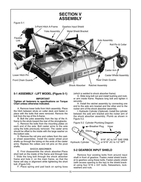
Figure 5-1<br />
3-Point Hitch A-Frame<br />
SECTION V<br />
ASSEMBLY<br />
Gearbox Input Shield<br />
Yoke Assembly<br />
Metal Shield Bracket<br />
Flexible<br />
Link<br />
Axle Assembly<br />
Roll Pin & Collar<br />
Caster Arm<br />
Lower Hitch Pin<br />
Front Chain Guards<br />
Caster Wheel Assembly<br />
Rear Chain Guards<br />
Shock Absorber<br />
Ratchet Assembly<br />
5-1 ASSEMBLY - LIFT MODEL (Figure 5-1)<br />
IMPORTANT<br />
Tighten all fasteners to specifications on Torque<br />
Chart unless otherwise indicated.<br />
A. Remove lower bolts from hitch assembly. Place<br />
the hitch between struts on cutter deck and fasten in<br />
place with the bolts that were removed. Remove the<br />
bolt from the top of the A-frame.<br />
B. Bolt the yoke assembly from the top of the A-<br />
frame to the struts toward the rear of the strongbacks.<br />
C. Remove the bolts from the mounting plates on<br />
each end of the axle. Bolt caster arms to the axle<br />
using the bolts previously removed. The caster arms<br />
should be offset to the inside with the large washer on<br />
the bottom side.<br />
D. Remove the roll pins and collars from the caster<br />
wheel assemblies. Install the caster wheel pivot<br />
shafts up through the tubing on the ends of the caster<br />
arms. Replace the collars and roll pins on the pivot<br />
shafts.<br />
SHOCK ABSORBER<br />
E. First disassemble the shock absorber.Place<br />
short bolt on the inside of the frame and through hole<br />
1. Slide the long bolt through the shock absorber<br />
frame and hole 2, on the main frame, so that the<br />
frame will stay in alignment while tightening the short<br />
bolt. (Figure 5-6)<br />
F. Place spring and pad back on spring boss<br />
15<br />
(which is welded to shock absorber frame).<br />
G .Slide long bolt out and install bushing and rocker<br />
arm inside frame. Replace long bolt and tighten it<br />
securely.<br />
H. Install the ratchet assembly by connecting one<br />
end to the axle arm bracket and the other end to the<br />
rocker arm of the shock absorber assembly.<br />
I. Hydraulic Cylinder (Optional)- Install the cylinder<br />
between the axle arm bracket and the rocker arm of<br />
the shock absorber assembly. Plumb as shown in<br />
Figure 5-2.<br />
Figure 5-2 Cylinder Plumbing Diagram<br />
Breather Plug Hose<br />
Elbow<br />
Hydraulic Cylinder<br />
5-2 GEARBOX INPUT SHIELD<br />
9/16” JIC to 3/4” SAE ORB<br />
or 9/16” JIC to 1/2” NPT<br />
Remove four existing bolts from around input<br />
shaft in front of gearbox. Fasten metal shield bracket<br />
to gearbox using these bolts. Fasten plastic shield<br />
(with access opening to the top) to the shield bracket<br />
using four 5/16 x 3/4” bolts, flatwashers, lockwashers<br />
and nuts.