BUSH
Operator's Manual 307 SERIES ROTARY CUTTERS - Caribe Turf
Operator's Manual 307 SERIES ROTARY CUTTERS - Caribe Turf
- No tags were found...

Create successful ePaper yourself
Turn your PDF publications into a flip-book with our unique Google optimized e-Paper software.
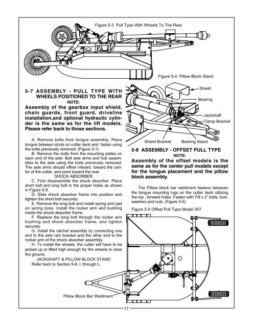
Figure 5-3 Pull Type With Wheels To The Rear<br />
Figure 5-4 Pillow Block Stand<br />
5-7 ASSEMBLY - PULL TYPE WITH<br />
WHEELS POSITIONED TO THE REAR<br />
NOTE:<br />
Assembly of the gearbox input shield,<br />
chain guards, front guard, driveline<br />
installation,and optional hydraulic cylinder<br />
is the same as for the lift models.<br />
Please refer back to those sections.<br />
Shield<br />
Bearing<br />
Jackshaft<br />
Clamp Bracket<br />
A. Remove bolts from tongue assembly. Place<br />
tongue between struts on cutter deck and fasten using<br />
the bolts previously removed. (Figure 3-1)<br />
B. Remove the bolts from the mounting plates on<br />
each end of the axle. Bolt axle arms and hub assemblies<br />
to the axle using the bolts previously removed.<br />
The axle arms should offset intward, toward the center<br />
of the cutter, and point toward the rear.<br />
SHOCK ABSORBER<br />
C. First disassemble the shock absorber. Place<br />
short bolt and long bolt in the proper holes as shown<br />
in Figure 5-9.<br />
D. Slide shock absorber frame into position and<br />
tighten the short bolt securely.<br />
E. Remove the long bolt and install spring and pad<br />
on spring boss. Install the rocker arm and bushing<br />
inside the shock absorber frame.<br />
F. Replace the long bolt through the rocker arm<br />
bushing and shock absorber frame, and tighten<br />
securely.<br />
G. Install the ratchet assembly by connecting one<br />
end to the axle ram bracket and the other end to the<br />
rocker arm of the shock absorber assembly.<br />
H. To install the wheels, the cutter will have to be<br />
jacked up or lifted high enough for the wheels to clear<br />
the ground.<br />
JACKSHAFT & PILLOW BLOCK STAND<br />
Refer back to Section 5-8, I. through L.<br />
Shield Bracket<br />
Bearing Stand<br />
5-8 ASSEMBLY - OFFSET PULL TYPE<br />
NOTE:<br />
Assembly of the offset models is the<br />
same as for the center pull models except<br />
for the tongue placement and the pillow<br />
block assembly.<br />
The Pillow block bar weldment fastens between<br />
the tongue mounting lugs on the cutter deck utilizing<br />
the top , forward holes. Fasten with 7/8 x 2” bolts, lockwashers<br />
and nuts. (Figure 5-5)<br />
Figure 5-5 Offset Pull Type Model 307<br />
Pillow Block Bar Weldment<br />
17