failsafe springpowered failsafe
SI-1-Q
SI-1-Q

You also want an ePaper? Increase the reach of your titles
YUMPU automatically turns print PDFs into web optimized ePapers that Google loves.
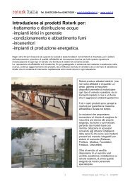
PRODUCT SPECIFICATION<br />
GENERAL DESCRIPTION<br />
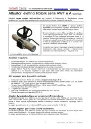
Rotork Skilmatic SI intelligent actuators offer a unique<br />
combination of the renowned features of Rotork actuation,<br />
such as the double sealing system and non-intrusive<br />
infrared commissioning capability, with the benefits of control<br />
and safety from Skilmatic range.<br />
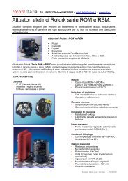
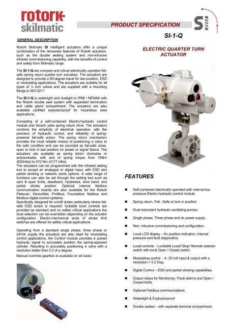
SI-1-Q<br />
ELECTRIC QUARTER TURN<br />
ACTUATOR<br />
The SI-1-Q are compact and robust electrically operated <strong>failsafe</strong><br />
spring return quarter turn actuators. The actuators are<br />
designed to provide a 90-degree travel for two-position, ESD<br />
or modulating applications. The actuators are suitable for all<br />
types of ¼ turn valves and are supplied with a mounting<br />
flange to ISO 5211<br />
The SI-1-Q is watertight and dustight to IP68 / NEMA6 with<br />
the Rotork double seal system with separated termination<br />
and cable gland compartment. The actuators are also<br />
available certified explosionproof for hazardous area<br />
applications.<br />
Consisting of a self-contained Electro-hydraulic control<br />
module and Scotch yoke spring return drive. The actuators<br />
combine the simplicity of electrical operation, with the<br />
precision of hydraulic control, and reliability of <strong>springpowered</strong><br />
fail-safe action. The spring return mechanism<br />
provides the most reliable means of positioning a valve to<br />
the safe condition and can be provided as fail-safe close,<br />
open or lock in last position on power or signal failure. The<br />
actuators are available as spring return clockwise or<br />
anticlockwise, with end of spring torque from 70Nm<br />
(620inlbs) to 472 Nm (4177 inlbs)<br />
The actuators can be programmed with the infrared setting<br />
tool to accept an analogue or digital input, with ESD and<br />
partial stroking or network cards options. A wide range of<br />
functions can also be set through the setting tool such as<br />
zero & span limits, deadband, hysteresis, slow band, and<br />
partial stroke position. Optional internal fieldbus<br />
communication boards are also available for the Rotork<br />
Pakscan, DeviceNet, Profibus, Foundation fieldbus and<br />
Modbus digital control systems.<br />
Specifically designed for on/off duties particularly where <strong>failsafe</strong><br />
ESD action is required, lockable local controls are<br />
provided as standard and on safety critical applications the<br />
local selection can be overridden depending on the actuator<br />
configuration. Electro-mechanical ends of stroke limit<br />
switches are offered for safety critical applications<br />
Operating from a standard single phase, three phase or<br />
24Vdc supply the actuators are also ideal for modulating<br />
control applications, the Control module provides a pulsed<br />
hydraulic signal to accurately position the spring-opposed<br />
cylinder. Resulting in accurately positioning a valve with a<br />
resolution better than 0.2 of a degree.<br />
Manual override gearbox is available on all sizes.<br />
FEATURES<br />
• Self-contained electrically operated with internal low<br />
pressure Electro hydraulic control module.<br />
• Spring return, Fail - Safe or lock in position<br />
• Dual redundant hydraulic oscillating pumps.<br />
• Single phase, Three phase and dc power supply<br />
• Non- Intrusive commissioning and configuration<br />
• Local LCD display – for position indication, internal<br />
pressure and fault diagnostics.<br />
• Local controls - Lockable Local/ Stop/ Remote selector<br />
switch with local Open / Closed switch.<br />
• Modulating control - 4- 20 mA input & output with a<br />
resolution < 0.2 Deg.<br />
• Digital Control – ESD and partial stroking capabilities.<br />
• Output relays for Monitoring / Fault alarms and Open /<br />
Closed limits<br />
• Optional Fieldbus communications<br />
• Watertight & Explosionproof<br />
• Double sealed – with separate terminal compartment.
SI-1-Q DIMENSION & MOUNTING DETAILS<br />
334<br />
394<br />
A<br />
B C<br />
436<br />
178<br />
G<br />
OE<br />
226<br />
D<br />
GEARBOX OPTIONAL<br />
F<br />
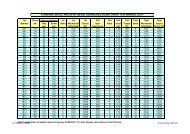
Dimensions<br />
Actuator Code<br />
SI-1-Q31 /<br />
SI-1-QA31<br />
SI- 1-Q41<br />
SI- 1-QA41<br />
SI-1-Q51<br />
SI-1-QA51<br />
SI-1-Q60<br />
SI-1-QA60<br />
SI-1-Q61<br />
SI-1-QA61<br />
A 374 374 394 394 394<br />
B 65 200 90 285 285<br />
C 200 200 285 285 285<br />
D 269 269 292 292 292<br />
ØE 400 400 400 600 600<br />
F 272 272 292 312 312<br />
G 119 119 131 131 131<br />
L 17 22 22 27 27<br />
M 30 30 30 37 37<br />
P 22.2 28.2 28.2 36.2 36.2<br />
ØV 70 70 102 102 102<br />
ØV1 102 102 125 125 125<br />
W M8x14 M8x14 M10x17 M10x17 M10x17<br />
W1 M10x17 M10x17 M12x21 M12x21 M12x21<br />
Weight (Kg)<br />
Weight With<br />
Gearbox (Kg)<br />
Note: - All 3-Phase actuators will have an extended Control Module. Dimension 436 mm will change to 491 mm<br />
OV<br />
+0.13<br />
-0.00<br />
x M DEEP<br />
OV1<br />
L P +0.5<br />
- 0.0<br />
Flange & Square Drive Details<br />
to ISO 5211<br />
Page 2 of 4
KEY MODEL CODE<br />
SI-1-Q50 - 0 0 2 1 - 0 0 0 - A - A<br />
Table 1 - Failure Mode<br />
Table 2 - Return speed options<br />
Table 3 - Supply voltage<br />
Table 4 - Control option<br />
Table 5 – Certification<br />
Table 6 - Cable entries<br />
Table 7 - Hydraulic fluid<br />
Table 8 – Mounting<br />
Table 9 - Accessories<br />
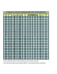
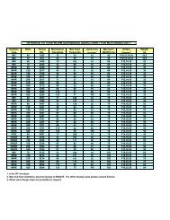
KEY MODEL CODE – ACTUATOR SIZE<br />
Code Torque Nm (Inlbs) Stroke speed (Seconds)<br />
Spring Return Hydraulic stroke Spring return<br />
clockwise<br />
Anticlockwise<br />
Start Mid Finish Start Mid Finish<br />
Hydrauli<br />
c<br />
Stroke<br />
Speed<br />
Spring Return Speed<br />
(See table 2)<br />
Std<br />
Single<br />
Std<br />
Dual<br />
ESD<br />
SI-1-Q31 SI-1-QA31 108 (956) 42 (372) 56 (495) 101 (894) 50 (442) 70 (620) 15 5 3 1.5<br />
SI-1-Q41 SI-1-QA41 221 (1956) 86 (761) 115 (1018) 206 (1823) 102 (903) 143 (1265) 30 9 5 2<br />
SI-1-Q51 SI-1-QA51 324 (2867) 125 (1106) 166 (1469) 330 (2920) 164 (1451) 233 (2062) 50 18 10 4<br />
SI-1-Q60 SI-1-QA60 580 (5133) 250 (2212) 310 (2743) 490 (4336) 240 (2124) 333 (2947) 100 33 18 6<br />
SI-1-Q61 SI-1-QA61 658 (5823) 252 (2230) 337 (2982) 671 (5938) 334 (2956) 472 (4177) 100 33 18 6<br />
TABLE 1 - FAILURE MODE<br />
CODE DESCRIPTION<br />
0 Fail- Safe (to release pressure)<br />
1 Fail in Position (lock pressure)<br />
2 Fail- Safe without pressure monitoring<br />
3 Fail in Position without pressure monitoring<br />
TABLE 2 – SPRING RETURN SPEED<br />
CODE DESCRIPTION<br />
0 Standard single internal solenoid.<br />
1 Std single internal solenoid & ESD<br />
2 Std dual internal solenoid<br />
3 Std dual internal solenoid & ESD<br />
4 Slow acting single internal solenoid<br />
TABLE 3 - SUPPLY VOLTAGE<br />
CODE DESCRIPTION<br />
0 Single phase 110V ac 50/60 Hz ± 10%<br />
1 Single phase 120V ac 50/60 Hz ± 10%<br />
2 Single phase 230V ac 50/60 Hz ± 10%<br />
3 Three phase 380V ac 50/60 Hz ± 10%<br />
4 Three phase 415V ac 50/60 Hz ± 10%<br />
5 Three phase 440V ac 50/60 Hz ± 10%<br />
6 Three phase 460V ac 50/60 Hz ± 10%<br />
7 Three phase 480V ac 50/60 Hz ± 10%<br />
8<br />
9 24V dc<br />
TABLE 4 - CONTROL<br />
CODE<br />
DESCRIPTION<br />
0 Digital control<br />
1 Analogue controls<br />
2 Pakscan<br />
3 Pakscan- analogue input<br />
4 Modbus single channel<br />
5 Modbus dual channel<br />
6 Profibus dual channel<br />
7 DeviceNet<br />
8 Foundation fieldbus<br />
9 Profibus single channel<br />
TABLE 5 –CERTIFICATIONS<br />
CODE DESCRIPTION<br />
0 WT – Watertight IP68<br />
1 ATEX ( European – Hazardous area)<br />
2 IEC (International – Hazardous area)<br />
3 FM ( US – Hazardous area)<br />
4 CSA ( Canada- Hazardous area)<br />
TABLE 6 – CABLE ENTRIES<br />
CODE DESCRIPTION<br />
0 M20 x 1.5P<br />
1 ½” NPT<br />
TABLE 7 – HYDRAULIC FLUID<br />
CODE DESCRIPTION<br />
0 Std 10 cSt mineral fluid<br />
1 20 cSt silicone fluid (low temperature –15 to -35 o C)<br />
2 15 cSt bio-degradable fluid<br />
TABLE 8 - MOUNTING<br />
CODE<br />
A<br />
B<br />
C<br />
DESCRIPTION<br />
Vertical stem above valve<br />
Vertical stem below-valve<br />
Valve stem horizontal<br />
TABLE 9 – ACCESSORIES<br />
CODE<br />
A<br />
B<br />
DESCRIPTION<br />
None<br />
Manual override<br />
NOTE:<br />
Stroke speed is typical for all actuators with no load at 20 o C ±10%<br />
Non standard torque’s are available on requests.<br />
All actuators are available with 4-20 or 20-4mA output, powered<br />
internally by an isolated 24Vdc supply or external customer supply.<br />
Page 3 of 4
SPECIFICATION<br />
Certification<br />
ATEX II 2G Eex dm IIB T3 (T amb -35° to +60°C) Approval Pending<br />
(See operating temperature).<br />
FM Class I, Zone1 AEx dm IIB T3 (Ta -35 o C to +60 o C) Approval<br />
Pending<br />
CSA - Approval Pending<br />
IEC - Approval Pending<br />
(See operating temperature)<br />
Safety Integrity: - Designed to SIL 2<br />
Enclosure: Watertight to IP68 / NEMA 6, double sealed protection<br />
with separate cable gland and termination compartment.<br />
Materials<br />
Control Module: Aluminium (BS 1490 Grade LM25<br />
Actuator Body: Anodised Aluminium<br />
Actuator Springs: Corrosion protected spring steel<br />
Switchbox: Aluminium (GaiSi 10Mg Din 1725/2).<br />
Mounting Bracket: Steel.<br />
Piping:<br />
316 Stainless Steel (hard piped).<br />
Paint Finish: Standard 2 Pack Epoxy silver grey (150microns<br />
thick).<br />
Mechanical<br />
Operating<br />
Temperature:<br />
Standard –20°C to +60°C (-4°F to 140°F).<br />
Optional –40°C to +60°C (-40°F to 140°F)<br />
(See table 7 Hydraulic fluid).<br />
Torque / Speed: See Key code table (page 3).<br />
Stroke: 0° to 92°, adjustable between 80° and 92<br />
Weight: See dimensional detail (page 2).<br />
Failure Mode:<br />
Action:<br />
Hydraulic Fluid:<br />
Fail-safe in the direction of the spring or<br />
Fail in last position.<br />
Spring return clockwise or anti-clockwise Code (A).<br />
Standard 10c.st mineral oil optional<br />
20c.st silicone oil or 15c.st bio-degradable oil<br />
Maximum Working Pressure: - 12 bar. (174lbf/in 2 )<br />
Pump Output: 17cc/sec at 5.5 bar at 50Hz.<br />
Manual Override: Optional gearbox<br />
Internal pressure transmitter: - 0-16Bar.Display indicate in 10psi<br />
increments.<br />
Mounting: Vertical or horizontals (see table 8)<br />
Electrical<br />
Electrical Supply: Single phase, 3-phase and 24vdc see table 3<br />
Supply Tolerance: Supply voltage ± 10%, frequency 50/60 Hz ±5%<br />
Power Consumption: 230Vac - 305VA(156watts), 110Vac 374VA<br />
(190 watts) reducing to 15VA(6watts) in balanced<br />
state. ESD option add 23VA (10.5watts)<br />
3- phase consult factory<br />
Pump coil protection: Cutout +110 o C (230 o F)<br />
Thermal fuse +130 o C (266 o F)<br />
Cable Entries: Four entries threaded M20 x 1.5P or ½” NPT.<br />
Position Feedback: 1K ohm. Conductive Plastic.<br />
Remote Digital inputs:-Open, Close, maintain,ESD and Partial<br />
Stroke – 24Vdc or 110vac 5mA minimum<br />
duration 300ms.<br />
Limit Switches: Two Electro mechanical SPDT volt free<br />
switches. Rating 5A) minimum at 230Vac<br />
(Table 9 accessories).<br />
Local controls: Lockable Local/ Stop/ Remote selector switch<br />
and local Open / Closed switch. Totally sealed<br />
with internal reed switches<br />
Non-intrusive setting: -<br />
Sealed control module with infrared setting from the<br />
Rotork standard Setting Tool. All values are held within<br />
EEPROM to maintain settings within the memory on<br />
power failure.<br />
Display: -<br />
Rotork LCD display with large segments to allow viewing<br />
of the valve position, internal pressure and diagnostics<br />
screens.<br />
LED’s are provided to indicate limits and intermediate<br />
state in the remote mode.<br />
Function Settings: - Deadband, Hysteresis and Partial stroking<br />
adjustable 0 to 9.9%<br />
Control<br />
Control Options: Digital ( Two position),.Emergency shutdown and<br />
Partial stroking<br />
Modulating, - input/output 4-20mA or 0-10Vdc.<br />
Output:- 4-20 or 20-4mA, powered internally by an isolated<br />
24Vdc supply or external customer supply.<br />
Resolution:<br />
Repeatability: