Profibus Actuator Control Profibus DP Option Card Installation Manual
Profibus Actuator Control Profibus DP Option Card Installation Manual
Profibus Actuator Control Profibus DP Option Card Installation Manual
- No tags were found...

Create successful ePaper yourself
Turn your PDF publications into a flip-book with our unique Google optimized e-Paper software.
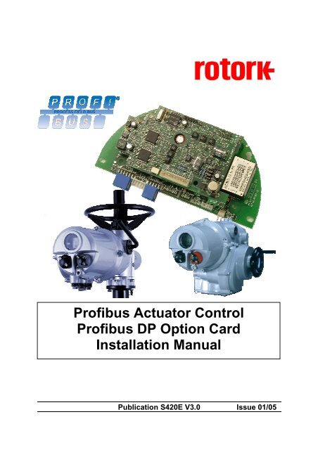
<strong>Profibus</strong> <strong>Actuator</strong> <strong>Control</strong><br />
<strong>Profibus</strong> <strong>DP</strong> <strong>Option</strong> <strong>Card</strong><br />
<strong>Installation</strong> <strong>Manual</strong><br />
Publication S420E V3.0 Issue 01/05
<strong>Profibus</strong> <strong>DP</strong> Mk2 <strong>Option</strong> <strong>Card</strong> <strong>Installation</strong> <strong>Manual</strong><br />
Note 1:<br />
Throughout this manual the <strong>Profibus</strong> <strong>DP</strong> Module (Mk2) may simply be referred to as the module<br />
or the <strong>Profibus</strong> module.<br />
Note 2:<br />
The information in this manual relates to the following firmware release<br />
<strong>Profibus</strong> Network Interface <strong>Card</strong> software version PNIC 1.20 (single) and 1.40 (Simple<br />
dual and RedCom dual)<br />
<strong>Actuator</strong> Interface <strong>Card</strong> software version M207<br />
Note 3:<br />
The <strong>Profibus</strong> <strong>DP</strong> Module (MK2) described in this manual is suitable for inclusion in Rotork IQ,<br />
IQT, and Q range actuators.<br />
As we are continually developing our products their design is subject to change without notice.<br />
© The contents of this document are copyright and must not be reproduced without the written<br />
permission of Rotork <strong>Control</strong>s Ltd.<br />
The name Rotork is a registered trademark<br />
Windows is a registered trademark by Microsoft Corporation<br />
<strong>Profibus</strong> is a registered trademark by PROFIBUS Nutzerorganisation e.V., Germany<br />
2 of 66 Publication S420E V3.0 Issue 01/05
Contents<br />
Contents<br />
Glossary of Terms:............................................................................................................................5<br />
Abbreviations: ...................................................................................................................................5<br />
1 INTRODUCTION.................................................................................................7<br />
1.1 General.....................................................................................................................................8<br />
2 PROFIBUS <strong>DP</strong> (MK2) OPTION CARD PROPERTIES.......................................9<br />
2.1 Mechanical properties ............................................................................................................9<br />
2.2 Electrical Properties .............................................................................................................10<br />
2.3 Operation and Storage .........................................................................................................10<br />
3 FITTING THE PROFIBUS <strong>DP</strong> (MK2) OPTION CARD......................................11<br />
3.1 Inside an IQ or IQT actuator.................................................................................................11<br />
3.2 Inside a Q actuator................................................................................................................12<br />
3.3 Replacing or Fitting a <strong>Profibus</strong> <strong>DP</strong> (Mk2) <strong>Option</strong> <strong>Card</strong> .....................................................13<br />
4 SINGLE AND DUAL DATA HIGHWAY CONFIGURATIONS ..........................15<br />
4.1 <strong>Profibus</strong> Data Highway.........................................................................................................15<br />
4.2 Segmented Single Highway System ...................................................................................16<br />
4.3 Redundant Systems – Simple Redundancy.......................................................................17<br />
4.3.1 Flying Redundancy Slave to Master Connection .............................................18<br />
4.3.2 System Redundancy Slave to Master Connection...........................................19<br />
4.4 Redundant Systems – RedCom Redundancy....................................................................20<br />
4.4.1 Extended Diagnostic Messages for RedCom ..................................................21<br />
4.5 Cable Types ...........................................................................................................................22<br />
4.6 Termination Network ............................................................................................................22<br />
4.7 Inter-connecting the Highway and Setting up the <strong>Profibus</strong> <strong>Card</strong> ....................................23<br />
4.7.1 Single Highway with Analogue Input................................................................23<br />
4.7.2 Dual Highway ...................................................................................................25<br />
5 THE ACTUATOR CYCLIC DATA SIGNALS....................................................27<br />
5.1 <strong>Control</strong> Outputs.....................................................................................................................27<br />
5.1.1 <strong>Control</strong>s Priority................................................................................................30<br />
5.1.2 <strong>Profibus</strong> <strong>Control</strong> using the ACTCON Register .................................................31<br />
5.1.3 <strong>Profibus</strong> <strong>Control</strong> using the POS_DV register ...................................................32<br />
5.1.4 The IQ ‘S’ contacts (<strong>Profibus</strong> DO’s) controlled by the O_STAT register..........32<br />
5.1.5 Multiport Position Selection using the PORTCM register (Future)...................33<br />
5.1.6 <strong>Profibus</strong> Network <strong>Control</strong> Disable feature ........................................................33<br />
5.2 Digital Input Status Feedback..............................................................................................34<br />
5.2.1 Digital Inputs from All <strong>Actuator</strong> Types ..............................................................35<br />
5.2.2 Digital Inputs from IQ and IQT <strong>Actuator</strong> ...........................................................37<br />
5.2.3 Digital Inputs from IQT <strong>Actuator</strong> .......................................................................38<br />
5.2.4 Digital Inputs Reporting the <strong>Profibus</strong> <strong>Card</strong> Condition.......................................39<br />
3 of 66 Publication S420E V3.0 Issue 01/05
<strong>Profibus</strong> <strong>DP</strong> Mk2 <strong>Option</strong> <strong>Card</strong> <strong>Installation</strong> <strong>Manual</strong><br />
5.3 <strong>Actuator</strong> Analogue Input Feedback ....................................................................................41<br />
5.4 Configuring the Registers to be Exchanged in Cyclic Communication..........................42<br />
6 PROFIBUS <strong>DP</strong> COMMUNICATION .................................................................43<br />
6.1 Electrical Specification.........................................................................................................43<br />
6.2 Protocol..................................................................................................................................43<br />
6.3 Single Highway, Single Channel .........................................................................................43<br />
6.4 Dual Highway, Dual Channel – SR Mode............................................................................44<br />
6.5 Single Highway Dual Channel – FR Mode ..........................................................................46<br />
6.6 Dual Channel Indication LEDs.............................................................................................47<br />
6.7 Basic Operation on Start up ................................................................................................48<br />
7 PARAMETERS .................................................................................................49<br />
7.1 Parameters set by GSD and <strong>DP</strong>-V1 Communication.........................................................49<br />
7.1.1 Limited Range Position Minimum and Maximum (Parameter 1 and 2)............51<br />
7.1.2 Deadband and Hysteresis (Parameter 3 and 4)...............................................51<br />
7.1.3 Slow Mode Range (Parameter 5).....................................................................52<br />
7.1.4 Motion Inhibit Timer (Parameter 6)...................................................................52<br />
7.1.5 <strong>Manual</strong> Movement Travel (Parameter 7) .........................................................53<br />
7.1.6 Valve Jammed Time (Parameter 8) .................................................................53<br />
7.1.7 Watchdog Timeout (Parameter 9)....................................................................53<br />
7.1.8 Action on Loss of Comms (Parameter 10) .......................................................53<br />
7.1.9 Comms Lost Position (Parameter 11) ..............................................................53<br />
7.1.10 Comms Fault Timer (Parameter 12).................................................................53<br />
7.1.11 Auxiliary Input Mask (Parameter 13)................................................................54<br />
7.1.12 ESD DI-4/Net Disable and Data Logger Disable (Parameter 14) ....................55<br />
7.1.13 Redundancy FR/SR Mode and Simple/RedCom Mode (Parameter 15)..........55<br />
7.1.14 Part Stroke Position (Parameter 16) ................................................................55<br />
7.1.15 Part Stroke Limit and Timeout (Parameter 17) ................................................56<br />
7.1.16 <strong>Actuator</strong> type (Parameter 18) ...........................................................................56<br />
7.2 Parameters viewed and set by <strong>DP</strong>-V1 Communication.....................................................56<br />
7.2.1 <strong>Actuator</strong> Tag Data (Parameter 20)...................................................................58<br />
7.2.2 Software Versions (Parameter 21 and 22).......................................................58<br />
7.2.3 Field Interface Type (Parameter 24) ................................................................58<br />
7.2.4 Permit GSD Parameterisation (Parameter 25).................................................58<br />
7.2.6 <strong>Control</strong> Outputs (Parameter 26 to 29)..............................................................58<br />
7.2.7 <strong>Actuator</strong> Feedback Data (parameter 30 to 36).................................................58<br />
7.2.8 Multiport feedback and Setup (Parameter 37 to 39) .......................................59<br />
7.2.9 Configure Data Exchange (Parameter 40).......................................................59<br />
7.2.10 Data Logger Information (Parameter 42 to 67) ................................................59<br />
7.2.11 Parameterisation Date (Parameter 68) ............................................................60<br />
7.3 Return to Defaults .................................................................................................................60<br />
8 SETTING UP AND MAINTAINING THE PROFIBUS MODULE .......................61<br />
8.1 Using a Network Configuration Tool...................................................................................61<br />
8.1.1 FDT (Field Device Tool) ...................................................................................61<br />
8.1.2 PDM (Process Device Manager)......................................................................62<br />
8.2 Setting up an IQ or IQT with the Setting Tool ....................................................................63<br />
4 of 66 Publication S420E V3.0 Issue 01/05
Contents<br />
8.3 Maintenance and Repair.......................................................................................................64<br />
8.4 Records..................................................................................................................................65<br />
Glossary of Terms:<br />
Address The unique address for a node on the fieldbus, range 0-126<br />
Fieldbus<br />
The digital, two-way, multi-drop <strong>Profibus</strong>-<strong>DP</strong> communication link<br />
Field Unit<br />
The <strong>Profibus</strong> option card fitted to the actuator<br />
Interoperability<br />
The capability for a device from one manufacturer to interact with that<br />
of another manufacturer, on a fieldbus network, without loss of<br />
functionality<br />
Master/Slave<br />
The method of communication used by the <strong>Profibus</strong>-<strong>DP</strong> Module. The<br />
fieldbus requires a <strong>Profibus</strong> master to control the data exchange on<br />
the highway.<br />
<strong>Profibus</strong> <strong>DP</strong><br />
The communication protocol used on the highway.<br />
<strong>Profibus</strong> <strong>DP</strong>-V0 and <strong>DP</strong>-V1 The cyclic (V0) and acyclic (V1) versions of the protocol supported by<br />
the Rotork module.<br />
PNO<br />
<strong>Profibus</strong> Nutzerorganisation – <strong>Profibus</strong> User Group, Germany<br />
RedCom Dual redundant system as defined in PNO 2.212<br />
Node<br />
A single device on the fieldbus<br />
RS485<br />
The electrical properties of the data highway as defined by the IEC<br />
61158 standard, copper conductors, 2 wire twisted pair.<br />
Segment<br />
A section of an RS485 fieldbus that is correctly terminated in its<br />
characteristic impedance. Each Segment can include up to 32<br />
devices.<br />
Abbreviations:<br />
Comms<br />
PFU<br />
RAM<br />
ROM<br />
RTU<br />
SW<br />
References:<br />
<strong>Profibus</strong> Guideline 2.112<br />
<strong>Profibus</strong> Guideline 2.212<br />
<strong>Profibus</strong> Guideline 2.152<br />
<strong>Profibus</strong> Guideline 2.162<br />
Communications<br />
<strong>Profibus</strong> Field Unit<br />
Random Access Memory<br />
Read Only Memory<br />
Remote Terminal Unit<br />
Software<br />
<strong>Installation</strong> Guideline for <strong>Profibus</strong> <strong>DP</strong>/FMS<br />
Specification Slave Redundancy<br />
Specification for <strong>Profibus</strong> Device Description and Device<br />
Integration – EDD<br />
Specification for <strong>Profibus</strong> Device Description and Device<br />
Integration – FDT<br />
5 of 66 Publication S420E V3.0 Issue 01/05
<strong>Profibus</strong> <strong>DP</strong> Mk2 <strong>Option</strong> <strong>Card</strong> <strong>Installation</strong> <strong>Manual</strong><br />
(This page is intentionally blank)<br />
6 of 66 Publication S420E V3.0 Issue 01/05
Introduction<br />
1 INTRODUCTION<br />
The Rotork <strong>Profibus</strong> <strong>DP</strong> <strong>Actuator</strong> <strong>Control</strong> option card (PFU) has been certified by the PNO as<br />
compliant with specifications IEC61158 and EN50170. The card supports both <strong>Profibus</strong> <strong>DP</strong>-V0 cyclic<br />
and <strong>Profibus</strong> <strong>DP</strong>-V1 acyclic messages. Three versions are available - single channel, simple dual<br />
channel and RedCom dual channel. The Simple dual channel card does not include the Redstate<br />
diagnostics whilst the RedCom dual channel card fully supports RedCom (Redundant Communication)<br />
extensions to the V1 protocol as specified by PNO for systems using either FR (Flying redundancy) or<br />
SR (System redundancy) configurations. The inclusion of acyclic message capability (V1) allows for<br />
system maintenance and asset management tools to be used. Electronic data sheets are available in<br />
GSD, EDD and DTM formats.<br />
<br />
<br />
<br />
<br />
<br />
<br />
<br />
<br />
<strong>Profibus</strong> <strong>DP</strong>-V0 and <strong>DP</strong>-V1 compliant<br />
RedCom redundancy included, both FR and SR modes<br />
GSD, EDD, DTM device description files available<br />
Supports Siemens PDM and FDT applications<br />
Address changes by master class 2, IR link (IQ and IQT only), FDT or PDM<br />
Zero internal stub length<br />
Mounted within the double sealed actuator enclosure<br />
All card settings are non-intrusive and can be made over the data highway<br />
The <strong>Profibus</strong>-<strong>DP</strong> Module circuits do not impinge on the actuator control electronics; the actuator itself<br />
remains fully self-protecting. The module performs the tasks of network interface, actuator data<br />
collection and the issuing of actuator commands to open, stop, close, perform an ESD operation or<br />
move to a set position.<br />
Motor<br />
Electrical<br />
Compartment<br />
Handwheel<br />
IQ range<br />
IQT range<br />
Terminal Cover<br />
Local <strong>Control</strong>s<br />
Local <strong>Control</strong>s<br />
Terminal Cover<br />
Local <strong>Control</strong>s<br />
Electrical<br />
Compartment<br />
Electrical<br />
Compartment<br />
Handwheel<br />
Q range<br />
Handwheel Terminal Cover<br />
Fig 1: The <strong>Profibus</strong> <strong>DP</strong> Module (Mk2) <strong>Option</strong> <strong>Card</strong> <strong>Actuator</strong> Compatibility<br />
7 of 66 Publication S420E V3.0 Issue 01/05
<strong>Profibus</strong> <strong>DP</strong> Mk2 <strong>Option</strong> <strong>Card</strong> <strong>Installation</strong> <strong>Manual</strong><br />
1.1 General<br />
The <strong>Profibus</strong> <strong>DP</strong> Module (Mk2) has three versions:<br />
<br />
<br />
<br />
Single Channel <strong>Profibus</strong> <strong>DP</strong> plus one analogue input channel<br />
Simple Dual Channel, independent isolated <strong>Profibus</strong> <strong>DP</strong> highways for redundant systems<br />
that do not support full RedCom<br />
RedCom Dual Channel, independent isolated <strong>Profibus</strong> <strong>DP</strong> highways for RedCom<br />
compliant systems<br />
The two dual channel versions have the same physical assembly, but are configurable to include the<br />
necessary extra messages for RedCom systems. PLC’s that cannot accept the extended diagnostic<br />
messages from RedCom slaves should use the Simple Dual channel card. The reporting of RedCom<br />
extended diagnostics can be selected from the GSD file.<br />
<strong>Profibus</strong> <strong>DP</strong><br />
Highway<br />
Analogue<br />
Input<br />
Single <strong>Profibus</strong> <strong>DP</strong> Highway + Analogue Input<br />
<strong>Profibus</strong> <strong>DP</strong><br />
Highway 1<br />
<strong>Profibus</strong> <strong>DP</strong><br />
Highway 2<br />
Simple Dual <strong>Profibus</strong> <strong>DP</strong> Highway Connections<br />
<strong>Profibus</strong> <strong>DP</strong><br />
Highway 1<br />
<strong>Profibus</strong> <strong>DP</strong><br />
Highway 2<br />
RedCom Dual <strong>Profibus</strong> <strong>DP</strong> Highway Connections<br />
Fig 2: The Types of <strong>Profibus</strong> <strong>DP</strong> Module (Mk2) <strong>Option</strong> <strong>Card</strong><br />
Communication Media<br />
Protocol<br />
Mode<br />
RS485 2 wire highway (single or dual), half duplex<br />
<strong>Profibus</strong> <strong>DP</strong>-V0 and <strong>DP</strong>-V1<br />
Master/Slave, module is a slave, cyclic and acyclic messaging<br />
8 of 66 Publication S420E V3.0 Issue 01/05
<strong>Profibus</strong> <strong>Card</strong> Properties<br />
2 PROFIBUS <strong>DP</strong> (MK2) OPTION CARD PROPERTIES<br />
2.1 Mechanical properties<br />
The PFU comprises two printed circuit boards connected together and the assembly is fitted inside the<br />
actuator electrical housing.<br />
<strong>Profibus</strong> Chip<br />
Network Interface <strong>Card</strong><br />
Termination<br />
Jumper links<br />
Interface <strong>Card</strong><br />
Fig 3: The <strong>Profibus</strong> dual highway module showing the NIC and Interface <strong>Card</strong> (IQ actuator)<br />
<br />
Network Interface <strong>Card</strong> - The small printed circuit board carries the <strong>Profibus</strong> <strong>DP</strong>, RS485<br />
highway connections and protection circuits.<br />
There are two versions of the Network Interface <strong>Card</strong>, one for a single<br />
highway and a second for two highways, Simple or RedCom Dual.<br />
(RedCom has two highway configurations, 2 highways for SR mode or<br />
one highway with two network interface connections for FR use.)<br />
Interface <strong>Card</strong> The larger motherboard is profiled to suit the actuator into which it fits.<br />
The IQ actuator assembly is shown. It carries the processor, memory<br />
components and power supplies for the module.<br />
The primary connection to the actuator circuits is by a multipin connector on the Interface <strong>Card</strong> that,<br />
due to its physical shape, may only be fitted in the correct polarisation. Internal wiring harnesses<br />
connect to the Interface <strong>Card</strong> for other signals and options within the actuator. The Network Interface<br />
<strong>Card</strong> carries the <strong>Profibus</strong> connector and termination and biasing resistors, this couples to the wiring<br />
harness routed to the terminal compartment of the actuator. Power for the Network Interface <strong>Card</strong> is<br />
taken from the Interface <strong>Card</strong> and the whole assembly is powered from the actuator.<br />
All the connectors are polarised to prevent incorrect insertion.<br />
9 of 66 Publication S420E V3.0 Issue 01/05
<strong>Profibus</strong> <strong>DP</strong> Mk2 <strong>Option</strong> <strong>Card</strong> <strong>Installation</strong> <strong>Manual</strong><br />
2.2 Electrical Properties<br />
The PFU connects directly to the Interface <strong>Card</strong> of the actuator. The PFU does not sit in the main<br />
control path for the actuator and does not affect the actuator control integrity.<br />
An EPROM stored program controls the processor on the module; the software can be updated by<br />
replacing this chip.<br />
The <strong>Profibus</strong> <strong>DP</strong> fieldbus data highway connections are fully isolated from the actuator electronics.<br />
2.3 Operation and Storage<br />
The PFU is designed to be stored in the actuator and operated within the same environment as the<br />
actuator. The constraints are:<br />
Operating temperature: -40 o C to +70 o C<br />
Storage temperature: -50 o C to +85 o C<br />
Relative Humidity: 5% to 95% (
SK1<br />
Fitting the <strong>Profibus</strong> card<br />
3 FITTING THE PROFIBUS <strong>DP</strong> (MK2) OPTION CARD<br />
3.1 Inside an IQ or IQT actuator<br />
The PFU is suitable for fitting into IQ Mk2 actuators with 3000 or 5000 series wiring diagrams and IQT<br />
with 6000 or 7000 series wiring diagrams. The connections and fitting in an IQT is similar to that for an<br />
IQ and the following information effectively relates to both actuator types. The PFU is normally located<br />
in the first option board slot inside the IQ/IQT electrical housing using connection SK1. In addition the<br />
PFU can be fitted inside IQ Mk1 actuators in certain cases.<br />
EPROM<br />
LK1<br />
SK3<br />
SK5 SK7 SK10<br />
SK8<br />
Fig 4: The <strong>Profibus</strong> Mk2 card profiled for the IQ or IQT actuator<br />
SK2<br />
The Interface card must be correctly profiled and loaded with the appropriate connectors to match the<br />
IQ/IQT actuator. The illustration (Fig 4) shows the IQ/IQT version of the PFU. The links for the bias<br />
resistors are shown in the ‘not terminated’ position.<br />
With the IQ/IQT actuator the remote inputs are always present (they are conditioned by the PFU) and<br />
there is an option to include Digital Outputs from relay contacts. If the PFU is required to operate the 4<br />
digital outputs that can be controlled from the card then the Extra Relay Indication card associated<br />
with these outputs must be fitted into the actuator. The following table describes the wiring harnesses<br />
and their function in the IQ and IQT actuator.<br />
PFU Socket<br />
Wiring Harness<br />
SK2<br />
24V power supply input from actuator<br />
SK3<br />
<strong>Profibus</strong> Fieldbus connection<br />
SK5<br />
Remote Digital Input connections<br />
SK7 Digital Output connections 1<br />
SK8<br />
Data Logger Information<br />
SK10 Analogue Input connection 2<br />
Note: 1 – Requires Extra Relay Indication board to be fitted<br />
2 – Only available on Single Channel module, 3000-900 or 6000-900<br />
To restore the card to its factory defaults and the associated default parameter settings, LK1 on the<br />
Interface card should be fitted and the power cycled (see Fig. 6).<br />
11 of 66 Publication S420E V3.0 Issue 01/05
<strong>Profibus</strong> <strong>DP</strong> Mk2 <strong>Option</strong> <strong>Card</strong> <strong>Installation</strong> <strong>Manual</strong><br />
3.2 Inside a Q actuator<br />
The PFU is fitted in the option board position in this actuator. Only one option board may be fitted at<br />
any one time. The necessary internal components must also be present; in this case a potentiometer<br />
and auxiliary limit switches at end of travel must be fitted to the actuator.<br />
The illustration (Fig 5) shows the Q version of the circuit board. The links for the bias resistors are<br />
shown in the ‘not terminated’ position.<br />
EPROM<br />
LK1<br />
SK3<br />
SK9<br />
SK11<br />
SK10<br />
SK2<br />
Fig 5: The <strong>Profibus</strong> Mk2 card profiled for the Q actuator<br />
Digital Outputs from relay contacts are not supported from the Q actuator, nor is the ability to report<br />
the status of the remote control inputs as Digital Inputs. The following table shows the wiring<br />
harnesses that must be fitted and the function of each loom for the Q range actuator.<br />
PFU Socket<br />
Wiring Harness<br />
SK2<br />
24V power supply input from actuator<br />
SK3<br />
<strong>Profibus</strong> Fieldbus connection<br />
SK9<br />
Limit switches<br />
SK10 Analogue Input connection 1<br />
SK11<br />
Potentiometer<br />
Note: 1 - Only available on Single Channel module<br />
In a Q actuator there is a direct connection from PL2 on the Interface <strong>Card</strong> to SK5 of the actuator main<br />
board.<br />
To restore the card to its factory defaults and the associated default parameter settings, LK1 on the<br />
Interface card should be fitted and the power cycled (see Fig. 6).<br />
12 of 66 Publication S420E V3.0 Issue 01/05
SK1<br />
Fitting the <strong>Profibus</strong> card<br />
3.3 Replacing or Fitting a <strong>Profibus</strong> <strong>DP</strong> (Mk2) <strong>Option</strong> <strong>Card</strong><br />
The PFU should be replaced or fitted only in a suitable environment. The actuator must be made<br />
electrically safe before opening any covers and in the case of an IQ or IQT it is advisable to<br />
disconnect the internal battery. The electrical housing cover should be removed and the existing PFU<br />
carefully unplugged from its main connector. Once removed from the main connector the wiring loom<br />
connectors should be removed. The replacement board is fitted in the reverse order to removal. The<br />
wiring harnesses are polarised so that only the correct one will fit its mating part on the circuit board.<br />
If the operation is to fit a PFU for the first time then the necessary wiring looms must be added to the<br />
internal wiring harness of the actuator. The actuator wiring diagram shows the connectors and<br />
harnesses used. The wiring harnesses are fitted inside the actuator before attempting to fit the PFU.<br />
Once the looms are in place connect them to the PFU, then fit the PFU to the actuator main board<br />
connector.<br />
Once the module is fitted the actuator should be re-assembled and, in the case of the IQ or IQT, the<br />
battery replaced.<br />
The PFU must not be split between its Network Interface <strong>Card</strong> and the Interface card. Only complete<br />
assemblies should be fitted or exchanged.<br />
If at any time it is necessary to reset the card to its supplied default values the Network Interface card<br />
should be removed and a shorting link applied to LK1. The Interface card must then be put back in the<br />
actuator and the mains power cycled. The Network Interface card must then be re-assembled onto the<br />
interface board and the pair refitted into the actuator. LK1 is usually used as a mechanical connection<br />
link between the top and bottom boards.<br />
EPROM<br />
LK1<br />
SK2<br />
SK5 SK7 SK10<br />
SK8<br />
LK1<br />
Fig 6: The <strong>Profibus</strong> Mk2 Interface card showing the position of LK1 (NIC removed)<br />
13 of 66 Publication S420E V3.0 Issue 01/05
<strong>Profibus</strong> <strong>DP</strong> Mk2 <strong>Option</strong> <strong>Card</strong> <strong>Installation</strong> <strong>Manual</strong><br />
(This page is intentionally blank)<br />
14 of 66 Publication S420E V3.0 Issue 01/05
Single and Dual Data Highway Configurations<br />
4 SINGLE AND DUAL DATA HIGHWAY CONFIGURATIONS<br />
4.1 <strong>Profibus</strong> Data Highway<br />
The rules governing the installation and connection of a <strong>Profibus</strong> <strong>DP</strong> highway should be observed at<br />
all times to produce a successful installation. The highway does not allow power to be transferred and<br />
the <strong>Profibus</strong> module is powered from the actuator itself. The module can only report data when the<br />
actuator is powered up.<br />
PLC<br />
+5V<br />
+5V<br />
T<br />
T<br />
Terminator<br />
0V<br />
<strong>Profibus</strong> <strong>DP</strong> highway<br />
Screened cable<br />
0V<br />
Fig 7: Typical <strong>Profibus</strong> <strong>DP</strong> Data Highway<br />
The data highway must be terminated with a proper active termination network at each end of a<br />
segment. To ensure successful operation the highway itself should not use tapped spur or stub<br />
connections. The connection should be made in and out of each actuator in a daisy chain<br />
arrangement on separate terminals to eliminate any internal stubs cabling inside the actuator. The<br />
length of the highway and number of devices connected will vary from project to project. The standard<br />
permits up to 32 devices to be connected on a section, though one of these will be the PLC. If more<br />
devices are needed (up to the maximum addressable of 126) then repeaters may be added as<br />
required. Up to 9 repeaters can be used on a single highway provided no more than 4 are between<br />
any two devices.<br />
Data Rate (Baud) 9600 19200 45.45k 93.75k 187.5k 500k 1.5M<br />
Maximum Segment Length 1.2 km 1.2 km 1.2 km 1.2 km 1000m 400m 200m<br />
Maximum Highway Length 10 km 10 km 10 km 10 km 10 km 4 km 2 km<br />
Max number of<br />
311 311 311 311 311 311 311<br />
actuators/segment<br />
Note: 1 – The PLC or Repeater module will be one device. Max 32 devices/segment<br />
Since the data passes over a single 2 wire cable there are periods between messages when no<br />
devices are actively driving the lines. In order to ensure that data continues to flow correctly after<br />
these periods it is advisable to ensure the lines are biased to suitable voltage levels during the time<br />
the line is idle. The PFU contains active termination circuits that ensure suitable levels are maintained<br />
on the line even with no device transmitting. To select these termination components the appropriate<br />
internal links must be fitted. A simple termination resistor is also included and can be connected by<br />
linking the appropriate terminals (refer to the actuator wiring diagram).<br />
15 of 66 Publication S420E V3.0 Issue 01/05
<strong>Profibus</strong> <strong>DP</strong> Mk2 <strong>Option</strong> <strong>Card</strong> <strong>Installation</strong> <strong>Manual</strong><br />
4.2 Segmented Single Highway System<br />
Bus Master<br />
Segment 1<br />
Terminator<br />
Repeater<br />
Segment 2<br />
Powered<br />
Active<br />
Terminator<br />
Segment 3<br />
Repeater<br />
Fig 8: <strong>Profibus</strong> Single Channel Data Highway Topology<br />
The data highway may be connected as several segments coupled by repeaters. The repeaters or<br />
actuator slaves will require termination components if they are on the end of the segment. Alternately<br />
separately powered active termination devices can be used so that when the actuator is switched off<br />
the bus performance is not affected.<br />
Maximum number of devices participating<br />
in the exchange of data<br />
Maximum number of devices per segment<br />
including repeaters<br />
Maximum number of segments in series<br />
127 (addresses from 0 to 126, 0 is usually the PLC)<br />
32<br />
EN50170 specifies a maximum of 4 repeaters between<br />
any two devices. Some manufacturers of repeaters<br />
allow more than this number.<br />
16 of 66 Publication S420E V3.0 Issue 01/05
Single and Dual Data Highway Configurations<br />
4.3 Redundant Systems – Simple Redundancy<br />
The Simple Dual Channel <strong>Profibus</strong> <strong>DP</strong> (Mk2) <strong>Option</strong> <strong>Card</strong> version has two redundant communications<br />
channels. Like the RedCom version, this card supports two types of redundant operation.<br />
SR – System Redundancy (One common slave address)<br />
FR – Flying Redundancy (Two slave addresses offset by 64)<br />
The Simple Dual Channel card is suitable for all PLC’s where redundant highways are being used.<br />
This option does not report the extended diagnostic bytes relating to the card’s redundant status.<br />
These two connection options allow for redundancy protection against either a failure of the highway<br />
(SR mode) or failure of the card interface channel (FR mode). Most dual channel systems use two<br />
highways and one connection to each, so the most common use for this card is in SR mode. The<br />
functionality and provisions of the card are identical to the RedCom version except in the way the card<br />
reports its status on the highway.<br />
There are a number of PLC systems, including older PLC’s, that do not have the ability to use the<br />
RedCom system and as a consequence they are likely to report errors when connect to a RedCom<br />
compliant card. If the PLC does not support the RedCom standard then the Simple Redundant card<br />
must be used.<br />
<strong>Control</strong> System Master<br />
<strong>Profibus</strong><br />
Primary Slave<br />
<strong>Profibus</strong><br />
Backup Slave<br />
Interface <strong>Card</strong><br />
<strong>Actuator</strong><br />
Redundant Slave<br />
Fig 9: <strong>Profibus</strong> <strong>DP</strong> (Mk2) Simple Dual Redundant <strong>Option</strong> Block Diagram<br />
The <strong>Profibus</strong> <strong>DP</strong> (Mk2) Simple Dual Channel card includes:<br />
Two <strong>Profibus</strong> Connections, Channel 1 and Channel 2<br />
Selectable FR/SR mode<br />
No Extended Diagnostics<br />
A Simple Dual Channel card can be altered to a RedCom Dual Channel card, or vice versa, by<br />
entering the appropriate value in parameter 15 in the GSD file.<br />
17 of 66 Publication S420E V3.0 Issue 01/05
<strong>Profibus</strong> <strong>DP</strong> Mk2 <strong>Option</strong> <strong>Card</strong> <strong>Installation</strong> <strong>Manual</strong><br />
4.3.1 Flying Redundancy Slave to Master Connection<br />
Primary Master<br />
Backup Master<br />
n<br />
64+n<br />
Primary<br />
Backup<br />
Slave<br />
FR<br />
Fig 10: <strong>Profibus</strong> <strong>DP</strong> (Mk2) Flying Redundancy Connection<br />
With FR (Flying Redundancy) the aim is to protect against a failure of the <strong>Profibus</strong> Interface. The data<br />
highway is considered to be more reliable than the connection interface. There is a single data<br />
highway and both the <strong>Profibus</strong> card inputs are connected to it. The card must be set to FR mode and it<br />
then adopts a fixed offset of 64 between the set address (used for primary communication) and the<br />
backup communication address.<br />
When the card is powered ‘on’, Channel 1 will be the Primary channel. If the card does not enter<br />
Configuration Mode within 1 second (because there is no Master present) then Channel 2 will take<br />
over as Primary, once again if there is no communication within 1 second, then it will revert to Channel<br />
1 and now it will wait 2 seconds before Channel 2 assumes Primary status. The switch over time will<br />
increase by a factor of 2 each time until it reaches its maximum of 32 seconds. It will continue to<br />
switch channels using a 32 second switch over time until one channel receives PLC messages.<br />
In the event of a failure of the Primary channel, the Backup automatically changes to use the Primary<br />
address. Hence for all control purposes the Master only uses the Primary address. The Backup<br />
address can be used for exchanging data but any commands to move the actuator directed to the<br />
backup address will be ignored. If a configuration message is sent to the Backup address that is<br />
different to the one sent to the Primary address it will accepted, but not actioned. The data exchanged<br />
between the Master and the Primary includes information on the status of the device and hence the<br />
availability of a Backup should the Primary fail.<br />
<br />
<br />
<br />
<br />
<br />
<br />
<br />
<br />
Single Data Highway, two communication ports<br />
Channel 1 is Primary on power up<br />
Default method is SR mode, to achieve FR the associated parameter must be altered<br />
Fixed offset of 64 between Primary and Backup addresses<br />
Backup automatically adopts Primary address if Primary fails.<br />
V0 cyclic Commands to Backup ignored<br />
Reports the status of Primary and Backup to the Master<br />
Configuration and Parameterisation changes only over the Primary address<br />
18 of 66 Publication S420E V3.0 Issue 01/05
Single and Dual Data Highway Configurations<br />
4.3.2 System Redundancy Slave to Master Connection<br />
First Master<br />
n<br />
n<br />
Primary<br />
Backup<br />
Slave<br />
m<br />
m<br />
Primary<br />
Backup<br />
Slave<br />
Second Master<br />
SR<br />
Fig 11: <strong>Profibus</strong> <strong>DP</strong> (Mk2) System Redundancy Connection<br />
With SR (System Redundancy) there are two data highways and the aim of the redundancy is to<br />
secure communication with the actuator even if one of the highways fails. Although two masters are<br />
shown they will normally be a Primary and Backup pair and communication will occur directly between<br />
them. SR mode is the default for all dual <strong>Profibus</strong> cards.<br />
The <strong>Profibus</strong> card has two communication channels and both have the same slave address. As with<br />
the FR mode, when the card is powered ‘on’, Channel 1 will be the Primary channel. If the card does<br />
not enter Configuration Mode within 1 second (because there is no Master present) then Channel 2<br />
will take over as Primary, once again if there is no communication within 1 second, then it will revert to<br />
Channel 1 and now it will wait 2 seconds before Channel 2 assumes Primary status. The switch over<br />
time will increase by a factor of 2 each time until it reaches its maximum of 32 seconds. It will continue<br />
to switch channels using a 32 second switch over time until one channel receives PLC messages.<br />
In the event of a failure of the Primary channel the Backup automatically changes to become Primary<br />
and communication will be established with the Second master on the second highway. The Backup<br />
channel can be used for exchanging data but any commands to move the actuator directed to the<br />
backup channel will be ignored. If a configuration message is sent to the Backup channel that is<br />
different to the one sent to the Primary it will be ignored. The data exchanged between the Master and<br />
the Primary includes information on the status of the device and hence the availability of a Backup<br />
should the Primary fail.<br />
<br />
<br />
<br />
<br />
<br />
<br />
<br />
Two Data Highways, two communication ports<br />
Channel 1 is Primary on power up<br />
Default communication method is SR mode<br />
Both channel have the same address<br />
V0 cyclic Commands to Backup channel are ignored<br />
Reports the status of Primary and Backup to the Master<br />
Configuration and Parameterisation changes only over the Primary channel<br />
19 of 66 Publication S420E V3.0 Issue 01/05
<strong>Profibus</strong> <strong>DP</strong> Mk2 <strong>Option</strong> <strong>Card</strong> <strong>Installation</strong> <strong>Manual</strong><br />
4.4 Redundant Systems – RedCom Redundancy<br />
The RedCom Dual Channel <strong>Profibus</strong> <strong>DP</strong> (Mk2) <strong>Option</strong> <strong>Card</strong> version has two redundant<br />
communications channels. Like the Simple card, the RedCom card supports two types of redundant<br />
operation and the details are as described in <strong>Profibus</strong> Guideline 2.212 ‘Specification Slave<br />
redundancy’. The two modes are:<br />
SR – System Redundancy (One common slave address)<br />
FR – Flying Redundancy (Two slave addresses offset by 64)<br />
The Rotork <strong>Profibus</strong> <strong>DP</strong> (Mk2) RedCom Dual Channel <strong>Option</strong> <strong>Card</strong> obeys the <strong>Profibus</strong> REDCOM<br />
Specification for Redundant Communications. This includes 3 bytes of Extended Diagnostics for<br />
RedState. Not all PLC systems can accept these diagnostic messages.<br />
As with the Simple Redundant card, there are two basic considerations when looking at redundant<br />
systems, protection against the failure of the connecting cable and protection against failure of the<br />
device. Most systems consider cable protection to be the most important and this is termed ‘SR’ or<br />
System Redundancy. The alternate connection using only a single cable, but with two <strong>Profibus</strong><br />
connections is termed ‘FR’ or Flying Redundancy. With FR systems there are two <strong>Profibus</strong> interfaces<br />
on the slave, but only one slave so protection against failure of the <strong>Profibus</strong> interface is included. SR<br />
and FR are described in more detail in the previous section.<br />
<strong>Control</strong> System Master<br />
<strong>Profibus</strong><br />
Red<br />
Extensions<br />
Primary Slave<br />
<strong>Profibus</strong><br />
Red<br />
Extensions<br />
Backup Slave<br />
Interface <strong>Card</strong><br />
<strong>Actuator</strong><br />
Redundant Slave<br />
Fig 12: <strong>Profibus</strong> <strong>DP</strong> (Mk2) RedCom Dual Redundant <strong>Option</strong> Block Diagram<br />
The <strong>Profibus</strong> <strong>DP</strong> (Mk2) RedCom Dual Channel card includes:<br />
Two <strong>Profibus</strong> Connections, Channel 1 and Channel 2<br />
RedCom link between the two connections<br />
Redundancy extensions to the V1 protocol<br />
No loss of data during switching<br />
Selectable FR/SR mode<br />
Status reported in Extended Diagnostics data<br />
20 of 66 Publication S420E V3.0 Issue 01/05
Single and Dual Data Highway Configurations<br />
4.4.1 Extended Diagnostic Messages for RedCom<br />
The Redundancy Extensions to the standard V1 protocol allow the two channels to communicate<br />
between themselves to establish correct operation of the highway if there is a failure, both the Simple<br />
and RedCom versions of the card do this. In addition to these there are extra Extended Diagnostic<br />
messages that are reported to the PLC as part of the RedCom system that the Dual RedCom card<br />
reports. Not all PLC’s are RedCom compliant, so some are unable to understand these messages and<br />
as a consequence will mark the device as having an Error. If this is the case either reconfigure the<br />
<strong>Profibus</strong> card to be ‘Simple’ or disable the PLC’s diagnostics package that is looking at the extended<br />
diagnostics.<br />
A RedCom Dual Channel card can be altered to a Simple Dual Channel card, or vice versa, by<br />
entering the appropriate value in parameter 15 in the GSD file.<br />
The extended diagnostics is contained in 3 bytes in the diagnostic message and is reported by the<br />
Primary slave only:<br />
Description<br />
Headerbyte<br />
Status_Type<br />
Slot_Number<br />
Specifier<br />
Function<br />
Red_State_1<br />
Red_State_2<br />
Red_State_3<br />
Comment<br />
= 8 h<br />
= 9Fh<br />
= 0 h<br />
State of Primary slave<br />
State of Back Up slave<br />
Not used<br />
The information in the Red_State bytes is as below<br />
Bit No: 7 6 5 4 3 2 1 0 Description if set:<br />
This slave is the Back up<br />
This slave is the Primary<br />
There is a Hardware defect<br />
This slave is in Data Exchange mode<br />
Master State Clear<br />
Baud rate found<br />
Toh started (hold timer active – set if a change<br />
of channel is iminent<br />
Reserved<br />
21 of 66 Publication S420E V3.0 Issue 01/05
<strong>Profibus</strong> <strong>DP</strong> Mk2 <strong>Option</strong> <strong>Card</strong> <strong>Installation</strong> <strong>Manual</strong><br />
4.5 Cable Types<br />
The network must be connected using a suitable cable. Two conductors plus a shield are required and<br />
there is a <strong>Profibus</strong> specification for the cable. Type A cable should be used for all new installations.<br />
Amongst the cable manufacturers Belden have the PVC jacketed 3077F single pair 2 core cable,<br />
which meets the minimum requirement. Information on Belden cable may be found on the Belden web<br />
site (www.belden.com).<br />
Belden 3077F<br />
Data Pair<br />
Screen<br />
Type A <strong>Profibus</strong> <strong>DP</strong> Cable Specification (for all new installations)<br />
Impedance<br />
135 up to 165 ohm at a frequency of 3 to 20 MHz<br />
Cable capacitance 0.34 mm2 (corresponds to AWG 22)<br />
Cable type<br />
Twisted pair cable, 1x2 or 2x2 or 1x4 lines<br />
Resistance<br />
Txd/Rxd - N<br />
Txd/Rxd - P<br />
Single and Dual Data Highway Configurations<br />
4.7 Inter-connecting the Highway and Setting up the <strong>Profibus</strong> <strong>Card</strong><br />
The <strong>Profibus</strong> Mk2 variants allow for different highway connections. The ‘single channel’ can be used<br />
for simple highways, and where there is an analogue transmitter connected it will also return the value<br />
from the transmitter signal. The ‘dual channel’ (both Simple and RedCom compliant) is used for<br />
redundant highway applications where the highway integrity (SR mode) or the physical connection is<br />
important (FR mode).<br />
4.7.1 Single Highway with Analogue Input<br />
PLC/ Host<br />
r<br />
+<br />
<strong>Actuator</strong><br />
1B In<br />
Out<br />
L2<br />
1A<br />
In<br />
Out<br />
L1<br />
Data<br />
Highway<br />
r<br />
-<br />
Terminator<br />
r<br />
+<br />
<strong>Actuator</strong><br />
Fit L1 and L2 on the<br />
last actuator<br />
1B In<br />
Out<br />
1A<br />
In<br />
Out<br />
L2<br />
L1<br />
Analogue<br />
Input<br />
4-20 mA I/P A<br />
Tx<br />
I/P B<br />
Common<br />
+ Tx Power Supply -<br />
r<br />
-<br />
Fig 15: Single Highway + Analogue Connections<br />
With the single channel option the actuator is connected to only one highway and an additional input is<br />
provided for measuring and reporting an analogue variable. The connection of the actuator to the<br />
highway uses terminals 1A and 1B (in and out terminals), the terminal numbers depend on the<br />
actuator type and are indicated on the actuator wiring diagram. The highway should be arranged so as<br />
to eliminate any stub connections. The last actuator on the highway should have the termination<br />
resistor connected by linking the highway 1B terminal to the Terminator terminal and fitting the internal<br />
links LK1 and LK2 in the Terminate position. Take care to ensure that the correct polarity is observed<br />
on the data highway connection, all the 1A terminals must be used on one data line and all the 1B<br />
terminals on the other.<br />
23 of 66 Publication S420E V3.0 Issue 01/05
LK2<br />
SK1<br />
<strong>Profibus</strong> <strong>DP</strong> Mk2 <strong>Option</strong> <strong>Card</strong> <strong>Installation</strong> <strong>Manual</strong><br />
Data line 1B is positive with respect to data line 1A when the PFU is transmitting a ‘1’.<br />
Data line A is also called TxD/RxD-N<br />
Data line B is also called TxD/RxD-P<br />
If an analogue input is being used it is connected to the analogue input terminals. The <strong>Profibus</strong> card<br />
caters for both current and voltage analogue signals. There is no power supply on the card for the<br />
analogue transmitter and an external power supply must be used to power it.<br />
<br />
<br />
For voltage inputs connect I/P A to the positive signal and analogue Common to the<br />
negative signal from the transmitter<br />
For current inputs connect I/P A to I/P B (to insert the conditioning resistor). The current<br />
input positive is to I/P A and I/P B whilst the current input negative is connected to the<br />
analogue Common.<br />
Active termination resistors are included on the <strong>Profibus</strong> card. The jumper links LK1 and LK2 on the<br />
PNIC board are used to select the inclusion of these resistors.<br />
<br />
<br />
Fit LK1 and LK2 as shown to provide pull apart active termination to the network at this<br />
actuator and<br />
Link Terminals ‘Terminator’ and ‘<strong>Profibus</strong> A’ to add end of line termination<br />
EPROM<br />
LK3<br />
LK4<br />
LK2<br />
LK1<br />
Links shown<br />
in 'Terminate'<br />
position<br />
LK1<br />
SK3<br />
LK1<br />
SK5 SK7 SK10<br />
SK8<br />
SK2<br />
Fig 16: Single Highway Active Termination Links<br />
24 of 66 Publication S420E V3.0 Issue 01/05
Txd/Rxd - N<br />
Txd/Rxd - P<br />
Txd/Rxd - N<br />
Txd/Rxd - P<br />
Single and Dual Data Highway Configurations<br />
4.7.2 Dual Highway<br />
The most common application of the Dual channel card is for Dual Highways in SR (System<br />
Redundancy) applications. If FR (Flying Redundancy) is being used then a similar connection at the<br />
actuator applies, but only one channel will require termination at the end of the highway. The choice<br />
between Simple and RedCom compliant redundancy does not affect the connection options.<br />
Channel<br />
1<br />
PLC/ Host<br />
Data<br />
Highway 1<br />
Data<br />
Highway 2<br />
Channel<br />
2<br />
1B In<br />
Out<br />
1A<br />
In<br />
Out<br />
r<br />
+ <strong>Actuator</strong><br />
L2<br />
L1<br />
r<br />
-<br />
+<br />
2B In<br />
Out<br />
2A<br />
In<br />
Out<br />
L4<br />
L3<br />
-<br />
Terminator<br />
r<br />
+<br />
<strong>Actuator</strong><br />
1B In<br />
Out<br />
1A<br />
In<br />
Out<br />
L2<br />
L1<br />
Terminator<br />
2B In<br />
Out<br />
2A<br />
In<br />
Out<br />
r<br />
-<br />
+<br />
L4<br />
L3<br />
-<br />
Fig 17: Dual Highway SR Mode Connections<br />
The connection of the actuator to the highway uses terminals 1A /1B (in and out terminals) on highway<br />
1 and 2A/2B (in and out terminals) on highway 2, the terminal numbers depend on the actuator type<br />
and are indicated on the actuator wiring diagram. The highways should be arranged so as to eliminate<br />
25 of 66 Publication S420E V3.0 Issue 01/05
SK1<br />
<strong>Profibus</strong> <strong>DP</strong> Mk2 <strong>Option</strong> <strong>Card</strong> <strong>Installation</strong> <strong>Manual</strong><br />
any stub connections. The last actuator on the highway should have the termination resistors<br />
connected by linking the highway 1B terminal to the highway 1 Terminator terminal and fitting the<br />
internal links LK1 and LK2 in the Terminate position; and by linking the highway 2B terminal to the<br />
highway 2 Terminator terminal and fitting the internal links LK3 and LK4 in the Terminate position.<br />
Take care to ensure that the correct polarity is observed on the data highway connection.<br />
Data line 1B is positive with respect to data line 1A when the PFU is transmitting a ‘1’.<br />
Data line A is also called TxD/RxD-N<br />
Data line B is also called TxD/RxD-P<br />
Both the Dual card options default to System Redundancy; this allows two separate highways to be<br />
used. When the RedCom compliant version is used the card uses RedCom extensions to the standard<br />
<strong>DP</strong> V1 protocol to permit redundancy to be used in a controlled manner. The host system should be<br />
able to support V1 messages and RedCom, if it cannot then the Simple redundant option should be<br />
used.<br />
Active termination resistors are included on the <strong>Profibus</strong> card. The jumper links LK1 to LK4 on the<br />
PNIC board are used to select the inclusion of these resistors.<br />
<br />
<br />
Fit LK1, LK2, LK3 and LK4 as shown to provide pull apart active termination to the<br />
network at this actuator and<br />
Link Terminals ‘Terminator 1’ and ‘<strong>Profibus</strong> 1A’ and ‘Terminator 2’ to ‘<strong>Profibus</strong> 2A’ to add<br />
end of line termination<br />
LK4<br />
LK3<br />
LK2<br />
LK1<br />
EPROM<br />
Links shown<br />
in 'Terminate'<br />
position<br />
LK1<br />
SK3<br />
SK5 SK7 SK10<br />
SK8<br />
SK2<br />
Fig 18: Dual Highway Active Termination Links for SR mode<br />
26 of 66 Publication S420E V3.0 Issue 01/05
Input and Output Signals<br />
5 THE ACTUATOR CYCLIC DATA SIGNALS<br />
The <strong>Profibus</strong> <strong>DP</strong> Module (Mk2) allows the actuator to be controlled by, and to report data to, a suitable<br />
host device using <strong>Profibus</strong> <strong>DP</strong> protocol. This section explains the data signals that are presented<br />
during cyclic V0 data exchange and their meaning in relation to the actuator functionality. The register<br />
locations used for the data exchange is given later in this manual.<br />
This section also gives information on the other control inputs available for moving the actuator.<br />
PLC<br />
<strong>Actuator</strong><br />
Outputs - Commands<br />
Inputs - Feedback<br />
Fig 19: Input and Output Data Direction<br />
<strong>Profibus</strong> <strong>DP</strong> (RS485) data highway<br />
<br />
<br />
Outputs are defined as signals originating at the PLC and operating the actuator<br />
controls.<br />
Inputs are defined as signals originating at the actuator and fed back to the PLC over the<br />
<strong>Profibus</strong> network.<br />
Cyclic Data Exchange<br />
Output Registers<br />
Input Registers<br />
1 ACTCON 1 IDATA1/IDATA2<br />
2 POS_DV 2 IDATA3/IDATA4<br />
3 O_STAT 3 TORQUE<br />
4 PORTCM 4 POSITN<br />
5 TEMPER<br />
6 ANALOG<br />
7 PORTST<br />
Note:<br />
The actual registers exchanged during normal cyclic data exchange will depend on<br />
the Configuration set for the card. Section 5.4 contains information on the<br />
Configuration options available.<br />
5.1 <strong>Control</strong> Outputs<br />
The <strong>Profibus</strong> <strong>DP</strong> Module (Mk2) can be used to control the actuator and position the valve. The valve<br />
may be moved fully closed, fully open or to an intermediate position. Additionally the actuator can<br />
make the valve adopt an Emergency Shut Down position. The actuator may also be operated from its<br />
local controls or by hard wired direct contact inputs (in the case of the IQ and IQT the Auxiliary Input<br />
Mask must be correctly set).<br />
27 of 66 Publication S420E V3.0 Issue 01/05
<strong>Profibus</strong> <strong>DP</strong> Mk2 <strong>Option</strong> <strong>Card</strong> <strong>Installation</strong> <strong>Manual</strong><br />
As well as controlling the actuator the PFU can also be used to operate 4 discrete output relays when<br />
fitted to an IQ/IQT actuator with the relay card fitted.<br />
The control commands have three potential sources:<br />
<strong>Profibus</strong> <strong>DP</strong> network generated commands<br />
<strong>Actuator</strong> Local <strong>Control</strong>s<br />
Direct contact input controls<br />
The full list of commands is shown in the table. The actuator types show whether the command is<br />
applicable to that actuator type.<br />
Command IQ actuator IQT actuator Q actuator<br />
<strong>Profibus</strong> over the network<br />
Open <br />
Close <br />
Stop <br />
Emergency Shut Down <br />
Analogue Position Demand <br />
Partial Stroke <br />
Multiport Position <br />
Relay output DO-1 1 1 <br />
Relay output DO-2 1 1 <br />
Relay output DO-3 1 1 <br />
Relay output DO-4 1 1 <br />
Local <strong>Actuator</strong> <strong>Control</strong>s<br />
Open <br />
Close <br />
Stop <br />
Direct Hard Wired Inputs<br />
Open 2<br />
Close 2<br />
Stop/Maintain 2<br />
Emergency Shut Down (Network Disable) 23<br />
Open Interlock (active prevents opening) <br />
Close Interlock (active prevents closing) <br />
Note: 1 – Requires Extra Relay Indication board to be fitted<br />
2 – Push to Run action only. Maintained action not available if analogue positioning is<br />
used<br />
3 – Network Disable not available on Q range actuator<br />
– Multiport functions require a multiport actuator, not described in this manual<br />
28 of 66 Publication S420E V3.0 Issue 01/05
Input and Output Signals<br />
The <strong>Profibus</strong> <strong>DP</strong> network commands will operate the actuator provided –<br />
• Local/Local Stop/Remote selector is in ‘Remote’,<br />
• On IQ or IQT actuators, <strong>Profibus</strong> commands are not inhibited by the ‘Inhibit/DI-4’ input<br />
parameter setting and DI-4 condition<br />
• No interlock is active on IQ or IQT actuators.<br />
• There is no standing hard wired control input active<br />
• No alarm condition prevents it from moving<br />
Open A digital command to cause the actuator to open to the fully open<br />
position as indicated by the Open limit switch. Under correct operation<br />
the actuator stops either when the open limit switch is reached, when<br />
the torque exceeds the value set and the open limit switch has been<br />
reached, or a new command is sent over the network.<br />
Close A digital command to cause the actuator to close to the fully closed<br />
position as indicated by the Close limit switch. Under correct operation<br />
the actuator stops either when the close limit switch is reached, when<br />
the torque exceeds the value set and the close limit switch has been<br />
reached, or a new command is sent over the network.<br />
Note:<br />
Many IQ multi-turn actuators are set to open until the open limit switch is reached and,<br />
close until the closing on torque switch trips, but it is dependant on the type of valve.<br />
The IQT and Q normally operate 90-degree valves, use stop bolts on the actuator or<br />
gearbox, and stop when these are reached. The control room indication is always taken<br />
from the end of travel limit switch settings<br />
Stop With no other command present this digital command causes an<br />
actuator motor that is running to stop.<br />
<br />
Emergency Shut Down A digital command that causes the actuator to drive to its<br />
Emergency position. There are settings within the actuator to<br />
determine if this is a closed, open or stay put action.<br />
Analogue Position Demand This function is only available over the <strong>Profibus</strong> <strong>DP</strong><br />
network. To initiate Analogue Position <strong>Control</strong> the ACTCON register<br />
Position Enable bit must be set to 1 and all other bits to 0, enabling<br />
Position mode and a value must be written the Position DV register<br />
(range 0-100.0%, resolution 0.1%), the valve will open to the<br />
appropriate amount and stop in that position (within the deadband<br />
setting). If a subsequent digital command to open or close the valve is<br />
issued, from any source, this will take priority over the analogue<br />
position command. Once the setpoint is reached the positioning<br />
controller is switched off, but whilst the <strong>Profibus</strong> outputs are being<br />
written the positioner is continuously being updated. A new value in<br />
the Position DV register will cause a new position to be adopted and a<br />
new bit set in the ACTCON register will cancel positioning mode.<br />
29 of 66 Publication S420E V3.0 Issue 01/05
<strong>Profibus</strong> <strong>DP</strong> Mk2 <strong>Option</strong> <strong>Card</strong> <strong>Installation</strong> <strong>Manual</strong><br />
Provided limited range positioning is not invoked the values 0% and<br />
100% written to the Position DV register produce a special case<br />
output where the command is revised so as to fully close the valve to<br />
its tight shut off position (0%) and fully open the valve (100%).<br />
Partial Stroke The actuator will move the valve to an intermediate position and back<br />
to the start position provided it is at the correct end of travel position<br />
when the command is issued. The end to start from and the amount of<br />
travel are selected during parameterisation.<br />
<br />
Multiport Position On multiport actuators the port to move to can be selected using this<br />
command. The actuator will move directly to the selected port. Valves<br />
with up to 10 ports can be controlled.<br />
Relay Output DO1 to DO4 These 4 commands are used to energise and deenergise<br />
the internal relays on the additional relay board in an IQ or<br />
IQT actuator. (These outputs are referred to as S5-S8 in the standard<br />
actuator documentation when there is no <strong>Profibus</strong> <strong>DP</strong> Module in the<br />
actuator.) The resulting outputs can be used for operating other<br />
equipment such as a pump or indication light. The IQ/IQT actuator is<br />
not able to control these relays directly from the main board when the<br />
PFU is fitted. They will maintain their last state if power is removed<br />
from the actuator. On restoration of power the relays will be reset to<br />
their de-energised condition and the coils will report ‘0’.<br />
<br />
<br />
<br />
Hard Wired Open and Close These commands operate the actuator in the same way<br />
as the open and close commands sent over the <strong>Profibus</strong> highway.<br />
Hard Wired Stop The hard wired stop input acts as a change of state input. If the<br />
actuator is moving, opening the Stop input will stop the actuator. If the<br />
Stop input is already open and a <strong>Profibus</strong> command is sent to the<br />
actuator, the <strong>Profibus</strong> command will be initiated. To stop the actuator<br />
the hard wired input must be closed and opened again.<br />
Hard Wired ESD (Network Disable) The hard wired ESD may be set to causes the<br />
actuator to drive to its Emergency position. Alternately the input can<br />
be used to disable <strong>Profibus</strong> network control. The function of the input<br />
is determined by the parameterisation set into the PFU.<br />
5.1.1 <strong>Control</strong>s Priority<br />
Since there are three potential sources for control inputs the actuator and <strong>Profibus</strong> <strong>DP</strong> Module (Mk2)<br />
assign a priority for those occasions when two or more commands are applied simultaneously.<br />
In addition, for the IQ and IQT actuator, the remote control hard wired inputs can be used as discrete<br />
input signals, to report the status of other devices or as control inputs. The associated Auxiliary Input<br />
Mask parameter must be set for the IQ or IQT to select the required function. In the case of the hard<br />
wired input for ESD this can be configured either as an ESD/DI-4 signal or as a ‘<strong>Profibus</strong> Command<br />
Inhibit’ to prevent network control signals from moving the actuator.<br />
30 of 66 Publication S420E V3.0 Issue 01/05
Input and Output Signals<br />
High Priority<br />
Low Priority<br />
Local Stop Local Close Hard Wired Close <strong>Profibus</strong> Close<br />
Local Open Hard Wired Open <strong>Profibus</strong> Open<br />
Hard Wired ESD Hard Wired Stop <strong>Profibus</strong> Stop<br />
<strong>Profibus</strong> ESD<br />
<strong>Profibus</strong> Position<br />
<strong>Profibus</strong> Part Stroke<br />
Mechanically interlocked to prevent both at the same time<br />
The IQ/IQT can be set so that Local Stop has a higher priority than ESD<br />
Only one <strong>Profibus</strong> command is permitted at a time<br />
If a <strong>Profibus</strong> command is applied whilst Hard Wired Stop is present, stop is cancelled<br />
Fig 20: IQ and IQT <strong>Control</strong>s Priorities<br />
In the case of the Q actuator the control selection is slightly different because the actuator uses a<br />
different control circuit. The Local <strong>Control</strong>s have a higher priority than hard wired or <strong>Profibus</strong> controls<br />
and the hard wired and <strong>Profibus</strong> controls share the same priority level<br />
If the Stop/Maintain hard wired input is closed (to provide maintained action on the other<br />
contact inputs to the actuator) then position control via <strong>Profibus</strong> cannot be used.<br />
The recommended connection is to use only an open and close buttons or contacts and<br />
‘push to run’ mode where the actuator only moves whilst the contact is closed.<br />
If a <strong>Profibus</strong> and hard wired input are both present the control priority is set by the actuator<br />
priority setting<br />
High Priority<br />
Low Priority<br />
Local Stop Local Close Hard Wired Close<br />
Local Open Hard Wired Open<br />
Hard Wired ESD <strong>Profibus</strong> Close Hard Wired Stop/Maintain<br />
<strong>Profibus</strong> ESD <strong>Profibus</strong> Open <strong>Profibus</strong> Position<br />
<strong>Profibus</strong> Stop<br />
Mechanically interlocked to prevent both at the same time<br />
The action depends on the <strong>Actuator</strong> <strong>Control</strong> Priority setting<br />
Only one <strong>Profibus</strong> command is permitted at a time,<br />
A <strong>Profibus</strong> Position command must not be applied whilst Hard Wired Maintain is present<br />
A <strong>Profibus</strong> Stop command is not possible if Hard Wired Maintain is present<br />
Fig 21: Q <strong>Control</strong>s Priorities<br />
5.1.2 <strong>Profibus</strong> <strong>Control</strong> using the ACTCON Register<br />
A single register is provided to allow the digital control of the actuator. Writing to the individual bits in<br />
the register causes the actuator to open, close, stop, ESD, adopt Positioning mode or perform a<br />
Partial Stroke and at the same time cancels any other command set. The bit written changes any<br />
output states already set to the new value. Only one bit may be written in a command. If more than<br />
one bit is set then the whole register is ignored.<br />
31 of 66 Publication S420E V3.0 Issue 01/05
<strong>Profibus</strong> <strong>DP</strong> Mk2 <strong>Option</strong> <strong>Card</strong> <strong>Installation</strong> <strong>Manual</strong><br />
ACTCON Register<br />
Bit 6 - 15 Bit 5 Bit 4 Bit 3 Bit 2 Bit 1 Bit 0<br />
Reserved Part Stroke Position<br />
Enable<br />
ESD Open Close Stop<br />
5.1.3 <strong>Profibus</strong> <strong>Control</strong> using the POS_DV register<br />
The analogue position control function requires two registers to be set.<br />
A desired position value to move the valve to should be placed in the POS_DV register<br />
The ACTCON register must be set to Position mode ( 0010 hex)<br />
POS_DV Register<br />
Register value: 0 to 1000 (0 to 3E8)<br />
Position demand: 0.0% to 100.0% of valve travel<br />
When the ACTCON register with Position mode set is sent the actuator will position to the value set in<br />
the POS_DV register and any other commands that are currently being carried out will be cancelled.<br />
If the POS_DV register is set to 0% and limited range positioning is not being used the actuator will<br />
operate as though a ‘close’ command had been sent. Similarly if the POS_DV register is set to 100%<br />
under these conditions the actuator will interpret the instruction as an ‘open’ command.<br />
Note that when limited range positioning is used and the actuator is in the fully closed position a<br />
POS_DV value of 0%, or when the actuator is in the fully open position a PS_DV value of 100%, are<br />
not acted upon.<br />
5.1.4 The IQ ‘S’ contacts (<strong>Profibus</strong> DO’s) controlled by the O_STAT register<br />
The IQ/IQT actuator has four ‘S’ contact outputs that may be configured to report the status of the<br />
actuator with signals such as Open Limit, Closed Limit etc. These are identified as S1 to S4.<br />
In addition an optional additional relay board can be fitted with four more relays. The status of these<br />
relays is then adjusted by <strong>Profibus</strong> commands on outputs DO-1 to DO-4 in the O_STAT register.<br />
Writing a ‘1’ in the appropriate location energises the relay and ‘0’ de-energises the relay. Note that<br />
these relays are latching and, if energised, will not change state when the actuator power is removed.<br />
On restoration of power the relays will be reset to their de-energised condition.<br />
IQ or IQT with Additional Relay Output board fitted<br />
<strong>Actuator</strong><br />
Main<br />
Board<br />
S1 - S4<br />
PFU<br />
DO-1 to DO-4<br />
Output Board<br />
Fig 22: IQ and IQT relay outputs DO-1 to DO-4<br />
32 of 66 Publication S420E V3.0 Issue 01/05
Input and Output Signals<br />
O_STAT Register<br />
Bit 4 - 15 Bit 3 Bit 2 Bit 1 Bit 0<br />
Reserved DO-4 DO-3 DO-2 DO-1<br />
5.1.5 Multiport Position Selection using the PORTCM register (Future)<br />
The multiport actuator position selection requires the Configuration (see section 5.4) to be set to<br />
Configuration 10 and a value to be set into the PORTCM register corresponding to the desired port<br />
number to go to. In addition during parameterisation the number of ports and number of active ports<br />
must be set.<br />
A desired port value to move the valve to should be placed in the PORTCM register<br />
The CONFIG must be set to 10 for a multiport actuator.<br />
PORTCM Register<br />
Register value: 1 to 10 (1 to A hex)<br />
Position demand: Port 1 to Port 10<br />
The actuator will move directly to the port selected in the register each time the value is changed. If<br />
the actuator is set to Local and moved by the local controls, when returned to remote the positioning<br />
the PORTCM register will be adopted.<br />
The valve can have up to 10 ports and the number of active ports can be selected. There are two<br />
parameters available to make these settings.<br />
5.1.6 <strong>Profibus</strong> Network <strong>Control</strong> Disable feature<br />
It is possible to set the IQ or IQT ESD/DI-4 input so that the IQ/IQT actuator ignores open, stop, close,<br />
ESD and position control signals sent over the <strong>Profibus</strong> network. If the ESD DI-4 / Net Disable<br />
parameter is set to Active then when the ESD input is connection is made (i.e. 24 volts applied to<br />
ESD), <strong>Profibus</strong> control is not allowed. This feature is independent of the Auxiliary mask setting. When<br />
the ESD DI-4 / Net Disable parameter is set to active, no ESD will be available.<br />
This feature is not included in a standard Q range actuator.<br />
33 of 66 Publication S420E V3.0 Issue 01/05
<strong>Profibus</strong> <strong>DP</strong> Mk2 <strong>Option</strong> <strong>Card</strong> <strong>Installation</strong> <strong>Manual</strong><br />
5.2 Digital Input Status Feedback<br />
The <strong>Profibus</strong> <strong>DP</strong> Module (Mk2) cyclically reports over the network a comprehensive data set relating<br />
to the status of the valve, actuator and card settings as indicated in the table below. The conventional<br />
contact indications are also available from the actuator limit switches and indication contacts.<br />
Register Name<br />
Status Feedback<br />
IQ IQT Q<br />
actuator actuator actuator<br />
IDATA1/0 Register 0 Bit 0 <strong>Actuator</strong> Moving <br />
IDATA1/1 Register 0 Bit 1 Close Limit <br />
IDATA1/2 Register 0 Bit 2 Open Limit <br />
IDATA1/3 Register 0 Bit 3 Running Closed <br />
IDATA1/4 Register 0 Bit 4 Running Open <br />
IDATA1/5 Register 0 Bit 5 Remote selected <br />
IDATA1/6 Register 0 Bit 6 Local Stop selected <br />
IDATA1/7 Register 0 Bit 7 Local selected <br />
IDATA2/0 Register 0 Bit 8 Thermostat Tripped <br />
IDATA2/1 Register 0 Bit 9 Monitor Relay <br />
IDATA2/2 Register 0 Bit 10 Valve Obstructed <br />
IDATA2/3 Register 0 Bit 11 Valve Jammed <br />
IDATA2/4 Register 0 Bit 12 Valve Moving by Hand <br />
IDATA2/5 Register 0 Bit 13 Moving Inhibited <br />
IDATA2/6 Register 0 Bit 14 Position <strong>Control</strong> Enabled <br />
IDATA2/7 Register 0 Bit 15 Watchdog Recovery <br />
IDATA3/0 Register 1 Bit 0 Battery Low <br />
IDATA3/1 Register 1 Bit 1 Open Interlock input <br />
IDATA3/2 Register 1 Bit 2 Close Interlock input <br />
IDATA3/3 Register 1 Bit 3 DI –1 <br />
IDATA3/4 Register 1 Bit 4 DI –2 <br />
IDATA3/5 Register 1 Bit 5 DI –3 <br />
IDATA3/6 Register 1 Bit 6 DI –4 <br />
IDATA3/7 Register 1 Bit 7 Slow Mode <br />
IDATA4/0 Register 1 Bit 8 GSD Configuration Permitted <br />
IDATA4/1 Register 1 Bit 9 Reserved <br />
IDATA4/2 Register 1 Bit 10 <strong>Control</strong> Contention <br />
IDATA4/3 Register 1 Bit 11 Partial Stroke in Progress <br />
IDATA4/4 Register 1 Bit 12 Part Stroke Error <br />
IDATA4/5 Register 1 Bit 13 Primary (0) or Backup (1) <br />
IDATA4/6 Register 1 Bit 14 1 or 2 Channels Available <br />
IDATA4/7 Register 1 Bit 15 SR (0) or FR (1) mode <br />
Note: 1 – This bit is reported when within the slow mode band, but does not affect the actuator.<br />
34 of 66 Publication S420E V3.0 Issue 01/05
Input and Output Signals<br />
5.2.1 Digital Inputs from All <strong>Actuator</strong> Types<br />
<br />
<strong>Actuator</strong> Moving Whenever the actuator position is changing due to the motor running<br />
or in the case of the IQ or IQT if the output drive is moving, this bit will<br />
be set true (1).<br />
Close Limit This data bit indicates that the actuator has reached the closed<br />
position. The limit switch should be set slightly within the actual valve<br />
stroke to allow for torque seating or overshoot on closing without<br />
damaging the valve. The data bit will remain true (1) even if the<br />
position is passed through or exceeded.<br />
Open Limit This data bit indicates that the actuator has reached the open position.<br />
The limit switch should be set slightly within the actual valve stroke to<br />
allow for torque seating or overshoot on opening without damaging<br />
the valve. The data bit will remain true (1) even if the position is<br />
passed through or exceeded.<br />
<br />
Running Closed Whenever the actuator motor contactor used to drive the actuator in<br />
the closing direction is energised this bit will be true (1).<br />
Running Open Whenever the actuator motor contactor used to drive the actuator in<br />
the opening direction is energised this bit will be true (1).<br />
<br />
Remote Selected This bit is true (1) when the actuator three position remote/local<br />
stop/local selector is in the Remote position. The selector must be in<br />
this position for <strong>Profibus</strong> control to be permitted.<br />
Local Stop The actuator three position selector passes from Local to Remote or<br />
Remote to Local through the Local Stop position. The switch can also<br />
be placed in Local Stop. When the switch is in the Local Stop position<br />
this bit will be true (1). Remote control of the actuator is not possible<br />
when the selector is in this position.<br />
Local Selected This bit is true (1) when the actuator three position remote/local<br />
stop/local selector is in the Local position. Remote control of the<br />
actuator is not possible when the selector is in this position.<br />
Thermostat If the temperature of the motor windings rises above the thermostat<br />
trip value, the thermostat contact will open and this signal will be<br />
present (1). There are no adjustments for the temperature at which<br />
the thermostat trip operates. The motor will be stopped if the<br />
thermostat trips. Only once the motor has cooled down and the<br />
thermostat has reset itself can a new Remote, Host or Local<br />
command to move the actuator be carried out. A setting on the<br />
actuator main board allows the ESD command to override the<br />
thermostat. The bit will remain set at logic 1 until the motor cools down<br />
and the thermostat resets itself.<br />
35 of 66 Publication S420E V3.0 Issue 01/05
<strong>Profibus</strong> <strong>DP</strong> Mk2 <strong>Option</strong> <strong>Card</strong> <strong>Installation</strong> <strong>Manual</strong><br />
Monitor Relay This signal is true (1) when actuator remote control is not available.<br />
The actuator Monitor Relay status is a composite signal for several<br />
alarms. This signal will be set true if the actuator selector is in Local or<br />
Local Stop (not in Remote) or if the thermostat trips. The mains supply<br />
is also monitored and if one of the three phases is lost this bit is set. If<br />
the actuator is operated from a single phase supply and this is lost<br />
then communications with the actuator will also be lost. Where a 3<br />
phase supply is used, if the phase associated with the control circuits<br />
is lost then communications with the actuator will be lost.<br />
Note:<br />
<br />
Valve Obstructed This bit will be true (1) if the actuator stops in mid travel when not<br />
expected to do so after receiving a command to move. If the actuator<br />
torque exceeds the trip value set during commissioning then the motor<br />
will stop and motion will cease. The reason for the actuator stopping<br />
will be the high torque due to an obstruction and not a ‘Stop’ signal or<br />
reaching the desired setpoint position.<br />
The bit will remain true (1) until the actuator position changes by 2%<br />
or more.<br />
Attempting to restart the actuator to move towards the obstruction (even if the<br />
obstruction no longer exists) is not possible, the actuator will not restart. The actuator<br />
must be electrically reversed away from the obstruction before attempting to continue in<br />
the original direction.<br />
Valve Jammed This bit will be true (1) if the actuator is stationary at the end of travel<br />
and fails to move away from the seat of the valve when a network<br />
command requests it to do so. The actuator will trip on excessive<br />
torque due to the valve being jammed in the seat. The PFU fails to<br />
see movement and reports this status after the time set in the<br />
associated parameter during the PFU set up.<br />
The bit will remain true (1) until the actuator position changes by 2%<br />
or more.<br />
Note:<br />
Attempting to restart the actuator to move out of the seated position is not possible. The<br />
actuator must be reversed before it will run in the same direction again. The jammed<br />
seat must first be released manually before electrical control is attempted. The problem<br />
may be overcome by adjusting the actuator torque setting which is designed to provide<br />
extra power on leaving the seated position.<br />
<br />
<br />
Valve Moving by Hand The manual movement of the valve is reported as true (1) if the<br />
actuator is moved by the handwheel away from the last position. The<br />
percentage of travel required to trip the indication is set in the<br />
associated parameter during PFU set up.<br />
The bit will remain true (1) until the actuator is moved electrically by<br />
either the local controls or a network command.<br />
Moving Inhibited This bit will be true (1) when the Motion Inhibit Timer is active or the<br />
Interrupter Timer is active (IQ/IQT only), or both are active.<br />
36 of 66 Publication S420E V3.0 Issue 01/05
Input and Output Signals<br />
The Motion Inhibit Timer is used in position control to prevent the<br />
actuator from exceeding its prescribed number of starts per hour, or to<br />
reduce the effects of hunting during closed loop control.<br />
The Interrupter Timer in the IQ/IQT can be used over part or the entire<br />
actuator stroke to slow down the effective speed of valve travel.<br />
When under network control, the control signal does not need to be<br />
re-applied when this bit is true, as the control action will continue once<br />
the time has elapsed.<br />
Position <strong>Control</strong> Enabled This bit will be true (1) when a Position command is<br />
being actioned. This data can be used to indicate that positioning<br />
mode has control of the actuator.<br />
Watchdog Recovery The PFU watchdog automatically resets the processor if it is<br />
tripped. This bit will be true (1) following a watchdog trip for the time<br />
period set in the associated watchdog timeout parameter.<br />
5.2.2 Digital Inputs from IQ and IQT <strong>Actuator</strong><br />
Battery Low Applicable to IQ and IQT actuators only. The status of the internal<br />
battery is monitored and should it fall below a critical level this signal<br />
will become true (1). The battery is used to power the circuits used to<br />
keep track of the valve position when the actuator mains power is<br />
switched off. This battery is used only when the actuator has no power<br />
feed and the valve is actually moved.<br />
Open Interlock Applicable to IQ and IQT actuators only. The input contact to the<br />
Open Interlock is monitored by the PFU. Whenever the input contact<br />
is closed this bit will be true (1). If the actuator is not using the<br />
interlock function then this input can be used as a digital status<br />
feedback for a plant signal not associated with the actuator. If the<br />
interlock circuit is being used then permission must be granted before<br />
the actuator can be opened and the presence of this bit will indicate<br />
that opening is permitted and permission is granted.<br />
Close Interlock Applicable to IQ and IQT actuators only. The input contact to the<br />
Close Interlock is monitored by the PFU. Whenever the input contact<br />
is closed this bit will be true (1). If the actuator is not using the<br />
interlock function then this input can be used as a digital status<br />
feedback for a plant signal not associated with the actuator. If the<br />
interlock circuit is being used then permission must be granted before<br />
the actuator can be closed and the presence of this bit will indicate<br />
that closing is permitted and permission is granted.<br />
<br />
Digital Input DI-1 Applicable to IQ and IQT actuators only. This bit reports the status of<br />
the contact connected to the actuator hard wired Open terminals. The<br />
input can be used to control the actuator or simply to report the status<br />
of a plant feedback signal. The function is set in the Auxiliary Input<br />
Mask parameter which determines whether the bit is reported as true<br />
(1) for a closed contact or an open contact and whether the input<br />
37 of 66 Publication S420E V3.0 Issue 01/05
<strong>Profibus</strong> <strong>DP</strong> Mk2 <strong>Option</strong> <strong>Card</strong> <strong>Installation</strong> <strong>Manual</strong><br />
controls the actuator or not. Note that the input is always reported<br />
even when it is also controlling the actuator.<br />
<br />
<br />
<br />
Digital Input DI-2 Applicable to IQ and IQT actuators only. This bit reports the status of<br />
the contact connected to the actuator hard wired Close terminals. The<br />
input can be used to control the actuator or simply to report the status<br />
of a plant feedback signal. The function is set in the Auxiliary Input<br />
Mask parameter which determines whether the bit is reported as true<br />
(1) for a closed contact or an open contact and whether the input<br />
controls the actuator or not. Note that the input is always reported<br />
even when it is also controlling the actuator.<br />
Digital Input DI-3 Applicable to IQ and IQT actuators only. This bit reports the status of<br />
the contact connected to the actuator hard wired Stop/Maintain<br />
terminals. The input can be used to control the actuator or simply to<br />
report the status of a plant feedback signal. The function is set in the<br />
Auxiliary Input Mask parameter which determines whether the bit is<br />
reported as true (1) for a closed contact or an open contact and<br />
whether the input controls the actuator or not. Note that the input is<br />
always reported even when it is also controlling the actuator.<br />
Digital Input DI-4 Applicable to IQ and IQT actuators only. This bit reports the status of<br />
the contact connected to the actuator hard wired ESD terminals. The<br />
input can be used to control the actuator or simply to report the status<br />
of a plant feedback signal. The function is set in the Auxiliary Input<br />
Mask parameter which determines whether the bit is reported as true<br />
(1) for a closed contact or an open contact and whether the input<br />
controls the actuator or not. Note that the input is always reported<br />
even when it is also controlling the actuator.<br />
A configuration feature also allows DI-4 to be set to act as a ‘Disable<br />
Fieldbus <strong>Control</strong>’ input. In this mode when the input is made<br />
(irrespective of the Auxiliary Mask setting) the actuator cannot be<br />
controlled over the network. This can be useful during plant<br />
commissioning to prevent unwanted valve movement.<br />
5.2.3 Digital Inputs from IQT <strong>Actuator</strong><br />
Slow Mode Applicable to IQT actuators only. In positioning mode, when the IQT<br />
actuator approaches its setpoint the motor automatically switches to<br />
‘slow mode’ and the actuator runs at a lower speed. This allows any<br />
developed inertia to be dissipated and a better positional accuracy to<br />
be achieved without overshoot. The deviation from the setpoint at<br />
which slow mode is adopted is set in the associated parameter.<br />
When slow mode is in use this bit will be true (1).<br />
The IQ and Q actuators also report this bit, but these actuators do not<br />
have a slow mode capability.<br />
38 of 66 Publication S420E V3.0 Issue 01/05
Input and Output Signals<br />
5.2.4 Digital Inputs Reporting the <strong>Profibus</strong> <strong>Card</strong> Condition<br />
GSD Parameterisation Permitted If the actuator and card is being parameterised<br />
using either the FDT or PDM programmes and the associated device<br />
description files, then the ability to alter the card parameters by the<br />
GSD may need to be removed. The status of this bit shows if, during<br />
parameterisation after connection or power up the, the settings in the<br />
GSD file will be used or the existing settings will be retained. When<br />
the bit is true (1), GSD parameterisation is permitted.<br />
Note:<br />
On start up of the card following connection to the bus the PLC will conduct a<br />
sequence of events including setting the Configuration of the card and then adjusting<br />
the card Parameters. The configuration will be the one selected for this particular card<br />
when it was commissioned onto the <strong>Profibus</strong> highway (see later). The parameterisation<br />
will be in accordance with the values in the GSD file associated with the specific<br />
actuator. It is possible to set the card so that GSD parameterisation is ignored, this<br />
then allows the actuator to be powered off and on again without resetting any<br />
parameter values.<br />
<strong>Control</strong> Contention If an incorrect value is transmitted in the ACTCON register then<br />
there will be no control action and this bit will be true (1) until a valid<br />
ACTCON value is received. Only one bit may be set in the ACTCON<br />
register at a time.<br />
Partial Stroke in Progress When the actuator is performing a partial stroke this bit is<br />
true (1). Once the action is complete the bit is reset (0). If the partial<br />
stroke is interrupted by a new command then the bit will be reset.<br />
<br />
Part Stroke Error In order to perform a partial stroke of the valve, the starting position is<br />
specified as either the open limit or the close limit. If the actuator is<br />
commanded to perform a partial stroke when it is not in the correct<br />
starting position or when it is in a mid position this error is generated<br />
and the bit will be set (1).<br />
There is a timer associated with Partial Stroke that is set during<br />
parameterisation to a value long enough to cover a successful part<br />
stroke operation from end to mid position and back to the end. If the<br />
actuator fails to complete the partial stroke within the time set then this<br />
bit will be true (1).<br />
Once set, the Part Stroke Error bit will be reset to 0 when the actuator<br />
next moves at least 2% by either a manual or automatic operation.<br />
39 of 66 Publication S420E V3.0 Issue 01/05
<strong>Profibus</strong> <strong>DP</strong> Mk2 <strong>Option</strong> <strong>Card</strong> <strong>Installation</strong> <strong>Manual</strong><br />
Backup or Primary Channel This bit is used to indicate if the <strong>Profibus</strong> communication<br />
is to a channel on the card that is able to move the valve (Primary) or<br />
to a channel that is prevented from operating the valve (Backup).<br />
When the communication is to the Primary <strong>Profibus</strong> <strong>DP</strong> channel the<br />
bit will be off (0).<br />
Note: With a single channel card this bit will always indicate ‘Primary’ and be (0).<br />
With a dual card set to FR mode the card there is only one highway and the card uses<br />
two addresses, one per channel. If the communication is directed to the address for the<br />
backup channel this bit will be set to 1, and if it is to the address for the primary<br />
channel it will be set to 0.<br />
With a dual card set to SR mode only one address is used, but there are two highways.<br />
If the communication is direct on the highway connected to the backup channel of the<br />
card then the bit will be set to 1, if the highway is connected to the primary channel the<br />
bit will be set to 0.<br />
Valve control can only be achieved if this bit reports as a 0.<br />
1 or 2 Channels Available This bit indicates the condition of the second channel on<br />
a dual channel card. It will be true (1) if both channels are available<br />
and working on the card. It does not indicate the status of the<br />
connection or highway to the second channel.<br />
On a single channel card it will always report 0.<br />
If there is a fault on the second channel of a dual channel card it will<br />
report 0, indicating that the second channel is not working correctly.<br />
SR or FR Mode This bit indicates the addressing mode chosen for the card. When<br />
reporting as 0 the bit indicates that one address is being used. On a<br />
single channel card only one address is permitted.<br />
On a dual channel card a single address is used when two <strong>Profibus</strong><br />
<strong>DP</strong> highways are used and the System Redundancy is employed.<br />
If the bit reports as 1 then the card must be dual channel and the<br />
redundancy is using two addresses for Flying Redundancy<br />
configuration.<br />
40 of 66 Publication S420E V3.0 Issue 01/05
Input and Output Signals<br />
5.3 <strong>Actuator</strong> Analogue Input Feedback<br />
The <strong>Profibus</strong> <strong>DP</strong> Module (Mk2) makes available over the network a number of analogue variables.<br />
These contain information about the valve and actuator. If the single highway with analogue input<br />
variant of the <strong>Profibus</strong> <strong>DP</strong> Module (Mk2) is used, one associated plant measurement is also available.<br />
Name Register Range Analogue Feedback<br />
TORQUE 2<br />
0-120<br />
(0-78 hex)<br />
= 0-120%<br />
IQ<br />
actuator<br />
IQT<br />
actuator<br />
Q<br />
actuator<br />
<strong>Actuator</strong> Instantaneous<br />
Torque<br />
<br />
POSITN 3<br />
TEMPER 4<br />
ANALOG 5<br />
0-1000 (0-3E8 hex)<br />
= 0-100%<br />
32768 – 65535<br />
(8000 – FFFF hex)<br />
= -32767 to -1 O C<br />
0 (0 hex) = 0 O C<br />
1 – 32767<br />
(0001 – 7FFF hex)<br />
= 1 to 32767 O C<br />
0-1000<br />
(0-3E8 hex)<br />
= 0-100%<br />
Valve Position <br />
Temperature O C <br />
Analogue Input 1 <br />
PORTST 6<br />
1-10 (1-A hex)<br />
= Position 1 to 10<br />
Multiport position <br />
Note: 1 – Requires the Single Highway + Analogue Input <strong>Profibus</strong> <strong>DP</strong> Module (Mk2)<br />
Torque The currently developed torque value is reported as an Integer Value<br />
in the range 0 to 120 (0-78 hex) representing the percentage of<br />
actuator rated torque generated.<br />
Valve Position The current valve position is reported as an Integer Value in the range<br />
0 to 1000 (0 – 3E8 hex) representing the percentage position to 0.1%<br />
resolution.<br />
The IQ and IQT actuator automatically scales the valve position value<br />
reported from the setting of the limit switches.<br />
The Q actuator requires the valve to be stroked fully between the<br />
closed and open limit switches for the value to be automatically<br />
scaled. This scaling is retained in EEPROM when the actuator power<br />
is removed.<br />
If Limited Range Positioning is invoked by setting the appropriate<br />
parameters, then the reported valve position 0 to 100% follows the<br />
limited range of valve travel.<br />
Temperature The actuator internal temperature is reported as a 2’s compliment<br />
integer value in the range –32767 to +32767 O C.<br />
[A value of 0 is 0 O C, 32767 (7FFF hex) is 32767 O C, 65535 (FFFF<br />
hex) is –1 O C and 32768 (8000 hex) is –32767 O C.]<br />
41 of 66 Publication S420E V3.0 Issue 01/05
<strong>Profibus</strong> <strong>DP</strong> Mk2 <strong>Option</strong> <strong>Card</strong> <strong>Installation</strong> <strong>Manual</strong><br />
Analogue Input The current value of the analogue input is reported as an Integer<br />
Value in the range 0 to 1000 (0 – 3E8 hex) representing the<br />
percentage value to 0.1% resolution.<br />
The input may be 0 to 5V or 0 to 20mA d.c. from an externally<br />
powered field transmitter (the actuator does not provide the power for<br />
the transmitter).<br />
The input must be calibrated during the set up of the PFU using the<br />
Analogue Input Max parameter. Apply a 100% signal and write a<br />
value to the parameter, the current value will then be reported as<br />
100%. The scaling is retained in EEPROM when the actuator power is<br />
removed.<br />
<br />
Multiport Position On multiport actuators the current number of the port selected is<br />
reported as an integer in the range 1 to 10 (1-A hex).<br />
5.4 Configuring the Registers to be Exchanged in Cyclic Communication<br />
In the start up routine for <strong>Profibus</strong> communication the card firstly enters parameterisation mode and<br />
adjusts the card parameters according to the GSD file settings. Next the card enters configuration<br />
mode where the configuration settings in the GSD file are used to determine the registers to be<br />
exchanged with the PLC during the normal cyclic messaging.<br />
The configuration stage allows for the tailoring of the registers to be exchanged to allow the system to<br />
be tuned to improve data throughput. If certain information or controls are not required by the PLC<br />
then they may be left out of data exchange by choosing the appropriate configuration.<br />
Both the PLC and the card must be aware of the configuration chosen for successful data exchange.<br />
The <strong>Profibus</strong> <strong>DP</strong> Module (Mk2) has 10 possible configurations as indicated in the table. The default<br />
value is Configuration 1. The PLC must send a Check Configuration message during start up to<br />
confirm the Configuration to be used.<br />
Configuration 1 2 3 4 5 6 7 8 9 10<br />
OUPUTS<br />
(16 Bits each)<br />
ACTCON <br />
POS_DV <br />
O_STAT <br />
PORTCM <br />
INPUTS<br />
(16 Bits each)<br />
IDATA1 & IDATA2 <br />
IDATA3 & IDATA4 <br />
TORQUE <br />
POSITN <br />
TEMPER <br />
ANALOG <br />
PORTST <br />
42 of 66 Publication S420E V3.0 Issue 01/05
<strong>Profibus</strong> Communication<br />
6 PROFIBUS <strong>DP</strong> COMMUNICATION<br />
6.1 Electrical Specification<br />
Line Electrical Specification:<br />
RS485, two wire, half duplex<br />
6.2 Protocol<br />
<strong>Profibus</strong> <strong>DP</strong><br />
Supported Baud Rates<br />
Cyclic (V0) and Acyclic (V1) communication<br />
9k6, 19k2, 45k45, 93k75, 187k5, 500k, 1M5<br />
Data Speed (Baud) 9k6 19k2 45k45 93k75 187k5 500k 1M5<br />
Maximum Slave Response<br />
Delay Time (mS)<br />
15 15 15 15 15 15 50<br />
6.3 Single Highway, Single Channel<br />
When using a single channel version the following must be set up:<br />
Address With IQ and IQT actuators the address can be set using the IrDA<br />
communication link directly with the actuator and the IQ setting tool.<br />
For all actuator variants the address can be set over the highway<br />
using a Class 2 master.<br />
Baud Rate This is selected by the PLC<br />
Slave Configuration One of the 10 configurations for the slave must be chosen.<br />
<br />
Basic Parameterisation The basic parameters such as deadband and motion inhibit<br />
time can be set using either the GSD file or a suitable PDM or FDT<br />
utility. The default settings will be suitable for most systems.<br />
Communication will be established automatically between the PLC and the card once the correct GSD<br />
has been identified. If the actuator cover is opened there are several LED’s on the circuit board that<br />
are used to indicate communication activity. These indicate both the communication between the<br />
<strong>Profibus</strong> highway and the card and the communication within the cards two main processors.<br />
43 of 66 Publication S420E V3.0 Issue 01/05
SK1<br />
<strong>Profibus</strong> <strong>DP</strong> Mk2 <strong>Option</strong> <strong>Card</strong> <strong>Installation</strong> <strong>Manual</strong><br />
LED 4<br />
LED 3<br />
LED 2<br />
EPROM<br />
LED 1<br />
LK1<br />
SK3<br />
SK5 SK7 SK10<br />
SK8<br />
Fig 23: Single Channel <strong>Profibus</strong> card LED positions<br />
SK2<br />
LED Description State Function<br />
1 Channel 1 Data Exchange<br />
On (Red) In data exchange mode with PLC<br />
Off<br />
Not in data exchange mode<br />
2 Channel 1 RTS line<br />
On (Red) Ready to reply to PLC<br />
Off<br />
Not ready to respond<br />
3 Inter-processor comms<br />
Flash (Red) Inter-processor comms running<br />
Off<br />
No inter-processor comms<br />
Flash (Green) PLC comms not present<br />
4 Diagnostic<br />
Solid (Green) Data being exchanged with PLC<br />
Solid (Red) Fatal Error<br />
Flash (Green) After solid green shows comms lost<br />
6.4 Dual Highway, Dual Channel – SR Mode<br />
When using the Simple or RedCom Dual Channel card the mode for communication has to be<br />
selected between SR (System Redundancy) and FR (Flying Redundancy). This is chosen during<br />
parameterisation by the GSD file values or by using a parameterisation utility such as FDT or PDM.<br />
Redundancy The default setting for redundancy is SR mode<br />
In SR mode there are two highways and a redundantly configured PLC. The two channels on the card<br />
both use the same address. One channel is in Primary mode whilst the other is in Backup mode. The<br />
card is waiting for a communication message on the channel that is in Primary mode and the two<br />
channels will switch their mode whilst searching for comms. There is no definition between Channel 1<br />
and Channel 2 to determine which is in Primary mode. The two channels will both try to adopt Primary<br />
mode.<br />
When using either the Simple or the RedCom dual channel card in SR mode the following must be<br />
set up:<br />
Address The two channels share the same common address. With IQ and IQT<br />
actuators the address can be set using the IrDA communication link<br />
44 of 66 Publication S420E V3.0 Issue 01/05
<strong>Profibus</strong> Communication<br />
directly with the actuator and the IQ setting tool. For all actuator<br />
variants the address can be set over the highway using a Class 2<br />
master.<br />
Baud Rate This is selected by the PLC, both channels adopt the same baud rate<br />
Slave Configuration One of the 10 configurations for the slave must be chosen. Both<br />
channels will use the same configuration setting.<br />
Configuration can only be carried out on the Primary channel.<br />
<br />
Basic Parameterisation The basic parameters such as deadband and motion inhibit<br />
time can be set using either the GSD file or a suitable PDM or FDT<br />
utility. The default settings will be suitable for most systems. Both<br />
channels will adopt the same settings.<br />
Parameterisation can only be carried out on the Primary channel.<br />
IDATA4 Bit 5 indicates the channel status and will show if the channel<br />
in communication is the Primary or Backup.<br />
SR<br />
Master PLC<br />
Standby PLC<br />
Highway 1 Highway 2<br />
Primary Backup<br />
address # =n address # = n<br />
<strong>Profibus</strong> <strong>Card</strong><br />
Fig 24: System Redundancy – Two highway redundancy<br />
Note: SR Mode -<br />
• Both channels have the same slave address.<br />
• When the card is powered ‘on’ Channel 1 will be the Primary channel. After power<br />
up the card will seek a master to communicate with by alternating the channel 1<br />
and 2 between Primary and Secondary mode. The switch over time increases with<br />
each change to a maximum of 32 seconds. The card will continue to switch<br />
channels using a 32 second switch over time until one channel receives PLC<br />
messages.<br />
• It may be necessary for the PLC to wait until the correct channel is in Primary<br />
mode before communications is started.<br />
• If the Primary channel fails the Backup will automatically adopt Primary status and<br />
wait for messages from the second master.<br />
• The Backup channel can be used for exchanging data but any commands to move<br />
the actuator directed to the backup channel will be ignored.<br />
• If a configuration message is sent to the Backup channel that is different to the<br />
one sent to the Primary it will be accepted, but not carried out.<br />
45 of 66 Publication S420E V3.0 Issue 01/05
<strong>Profibus</strong> <strong>DP</strong> Mk2 <strong>Option</strong> <strong>Card</strong> <strong>Installation</strong> <strong>Manual</strong><br />
6.5 Single Highway Dual Channel – FR Mode<br />
On either the Simple or RedCom dual channel card the mode for communications may be set to FR<br />
(Flying Redundancy) in some cases. This will require the card’s GSD file to be changed or the<br />
parameter value altered by a PDM or FDT utility.<br />
Redundancy SR is the default mode, it must be altered for FR mode<br />
In FR mode there is one highway and a single PLC can be used. The two channels on the card use<br />
addresses offset by 64. One channel is in Primary mode and uses the base address whilst the other is<br />
in Backup mode using the base address plus 64. As with SR mode, the card is waiting for a<br />
communication message on the channel that is in Primary mode and the two channels will switch their<br />
mode whilst searching for comms. There is no definition between Channel 1 and Channel 2 to<br />
determine which is in Primary mode. The two channels will both try to adopt Primary mode. The<br />
difference here is that the PLC can communicate with the backup using a different address.<br />
When using either type of dual channel card in FR mode the following must be set up:<br />
Address The two channels have address offset by 64. Setting the base<br />
address will set the offset address. With IQ and IQT actuators the<br />
address can be set using the IrDA communication link directly with the<br />
actuator and the IQ setting tool. For all actuator variants the address<br />
can be set over the highway using a Class 2 master.<br />
Baud Rate This is selected by the PLC, both channels adopt the same baud rate<br />
Slave Configuration One of the 10 configurations for the slave must be chosen. Both<br />
channels will use the same configuration setting.<br />
Configuration can only be carried out on the Primary channel.<br />
<br />
Basic Parameterisation The basic parameters such as deadband and motion inhibit<br />
time can be set using either the GSD file or a suitable PDM or FDT<br />
utility. The default settings will be suitable for most systems. Both<br />
channels will adopt the same settings.<br />
Parameterisation can only be carried out on the Primary channel.<br />
IDATA4 Bit 5 indicates the channel status and will show if the channel<br />
in communication is the Primary or Backup.<br />
FR<br />
Master PLC<br />
Standby PLC<br />
Highway 1<br />
Primary Backup<br />
address # =n address # = 64+n<br />
<strong>Profibus</strong> <strong>Card</strong><br />
Fig 25: Flying Redundancy – One highway redundancy<br />
46 of 66 Publication S420E V3.0 Issue 01/05
SK1<br />
<strong>Profibus</strong> Communication<br />
Note: FR Mode -<br />
• Primary is offset from Backup address by 64.<br />
• When the card is powered ‘on’ Channel 1 will be the Primary channel. After power<br />
up the card will seek a master to communicate with by alternating the channel 1<br />
and 2 between Primary and Secondary mode. The switch over time increases with<br />
each change to a maximum of 32 seconds. The card will continue to switch<br />
channels using a 32 second switch over time until one channel receives PLC<br />
messages. The channel addresses alternate at this point.<br />
• The PLC need not wait for a particular channel to be in Primary mode before<br />
starting communications.<br />
• If the Primary channel fails the Backup will automatically adopt Primary address<br />
and wait for messages from the master.<br />
• The Backup channel address can be used for exchanging data but any commands<br />
to move the actuator directed to the backup address will be ignored.<br />
• If a configuration message is sent to the Backup address that is different to the<br />
one sent to the Primary it will be accepted, but not carried out.<br />
6.6 Dual Channel Indication LEDs<br />
If the actuator cover is opened there are several LED’s on the circuit board that are used to indicate<br />
communication activity. These indicate both the communication between the <strong>Profibus</strong> highway and the<br />
card and the communication within the cards two main processors.<br />
LED 4<br />
LED 3<br />
LED 6<br />
LED 1<br />
EPROM<br />
LED 2<br />
LED 5<br />
LK1<br />
SK3<br />
SK5 SK7 SK10<br />
SK8<br />
SK2<br />
Fig 26: Dual Channel <strong>Profibus</strong> card LED positions<br />
LED Description State Function<br />
1 Channel 1 Data Exchange<br />
On (Red) In data exchange mode with PLC<br />
Off<br />
Not in data exchange mode<br />
2 Channel 1 RTS line<br />
On (Red) Ready to reply to PLC<br />
Off<br />
Not ready to respond<br />
3 Inter-processor comms<br />
Flash (Red) Inter-processor comms running<br />
Off<br />
No inter-processor comms<br />
47 of 66 Publication S420E V3.0 Issue 01/05
<strong>Profibus</strong> <strong>DP</strong> Mk2 <strong>Option</strong> <strong>Card</strong> <strong>Installation</strong> <strong>Manual</strong><br />
LED Description State Function<br />
Flash (Green) PLC comms not present<br />
4 Diagnostic<br />
Solid (Green) Data being exchanged with PLC<br />
Solid (Red) Fatal Error<br />
Flash (Red) After solid green shows comms lost<br />
5 Channel 2 Data Exchange<br />
On (Red) In data exchange mode with PLC<br />
6 Channel 2 RTS line<br />
Off<br />
On (Red)<br />
Off<br />
Not in data exchange mode<br />
Ready to reply to PLC<br />
Not ready to respond<br />
6.7 Basic Operation on Start up<br />
Whenever a field device is powered up and it is found by the PLC it will<br />
go through the standard <strong>Profibus</strong> procedure of Parameterisation and<br />
Configuration before commencing Data Exchange. This exchange can<br />
include altering the address if the device has an address of 126 and<br />
the master supports address changes – master class 2.<br />
1) The first message – master sends a DIAG_req telegram.<br />
2) The response should be a DIAG_res with diagnostic data<br />
attached.<br />
3) If this is correct a Set_Parameter telegram is sent with the<br />
parameterisation data attached.<br />
4) The response should be a Short Ack message<br />
5) If a correct response is received a Check_Config telegram is sent<br />
6) The response should be a Short Ack message<br />
7) If this is correct a DIAG_req telegram is sent<br />
8) The response should be a DIAG_res with diagnostic data<br />
attached.<br />
9) If DIAG is not reporting an error data exchange commences.<br />
The Parameterisation data is extracted from the GSD file for the<br />
particular address of the slave device. The association between the<br />
GSD to be used and the address is made in the master during the<br />
configuration of the network on the master (a table is created). The<br />
association can also be defined in a Master 2 and sent to a Master 1 by<br />
the master to master comms. Most masters 1 devices permit the same<br />
device type (as described in the GSD) to have different GSD files, so<br />
allowing the GSD to be edited.<br />
Editing the GSD file guarantees that a device coming on line after<br />
having been switched off will have the correct settings. If FDT or PDM<br />
changes the same parameters as those installed by a GSD then the<br />
GSD values will replace those set by the FDT or PDM when the device<br />
is switched off and on again, or the PLC is powered off and back on,<br />
unless GSD parameterisation is not permitted.<br />
(See section 5.4 for information on the Configurations allowed).<br />
Fig 27: <strong>Profibus</strong> Start Up Sequence<br />
48 of 66 Publication S420E V3.0 Issue 01/05
Parameters<br />
7 PARAMETERS<br />
7.1 Parameters set by GSD and <strong>DP</strong>-V1 Communication<br />
<strong>Profibus</strong> defines a power on reset sequence for all devices as:<br />
Diagnostic Request<br />
Set Parameterisation<br />
Check Configuration / Set Configuration<br />
Diagnostic Request<br />
Data Exchange<br />
After a successful Diagnostic Request the Set Parameterisation Telegram is sent from the PLC. The<br />
Set Parameter message contains the user defined Parameter Data Unit (DU) of a minimum of 7 bytes,<br />
max 244 bytes. The first 7 bytes are mandatory and fixed. The following bytes contain the parameter<br />
values to be set and these are derived from the GSD file and the values in it. The response is a short<br />
acknowledgement (E5) with no data field if the Parameterisation is accepted.<br />
The <strong>Profibus</strong> <strong>DP</strong> Module (Mk2) GSD contains 19 configurable parameter registers sent in a 23 byte<br />
string. The first 3 bytes are <strong>Profibus</strong> Specific, the next 19 relate to the configurable parameters and the<br />
23 rd is reserved for future use. With the IQ and IQT actuator some of the parameters can be altered by<br />
using the infra-red communications link and the setting tool. All of them can be altered by the values in<br />
the GSD file or by a V1 communication tool such as PDM or FDT when the appropriate files are<br />
provided. It is possible to lock out parameterisation by GSD in the more sophisticated uses of this<br />
card. This facility is there to ensure that V1, FDT or PDM parameterisation is not lost on a power cycle.<br />
Care must be exercised with access to these parameter registers as they can alter the complete<br />
performance of the actuator. This section of the manual describes each variable parameter and should<br />
be used for reference when using the parameterisation tools.<br />
The parameters that may be set by the GSD exchange or V1 comms are:<br />
Parameter<br />
No.<br />
Description<br />
1 Limited Range Position<br />
Minimum<br />
0-100%<br />
0000 – 0064 hex<br />
2 Limited Range Position 0-100%<br />
Maximum<br />
0000 – 0064 hex<br />
3 Deadband 1 0.0 – 25.5% 2<br />
0000 – 00FF hex<br />
4 Hysteresis 1 0.0 – 25.5%<br />
0000 – 00FF hex<br />
5 Slow Mode Range 0 – 100%<br />
0000 – 0064 hex<br />
6 Motion Inhibit Time 0 – 255 sec<br />
0000 –00FF hex<br />
7 <strong>Manual</strong> Movement Travel 0 – 100%<br />
0000 – 0064 hex<br />
8 Valve Jammed Time 0 – 255 sec<br />
0000 – 00FF hex<br />
Value/Range<br />
Default<br />
Value<br />
0%<br />
0000 hex<br />
100%<br />
0064 hex<br />
5.0%<br />
0032 hex<br />
2.0%<br />
0014 hex<br />
5%<br />
0005 hex<br />
5 sec<br />
0005 hex<br />
10%<br />
000A hex<br />
5 sec<br />
0005 hex<br />
49 of 66 Publication S420E V3.0 Issue 01/05
<strong>Profibus</strong> <strong>DP</strong> Mk2 <strong>Option</strong> <strong>Card</strong> <strong>Installation</strong> <strong>Manual</strong><br />
Parameter<br />
No.<br />
Description<br />
Value/Range<br />
9 Watchdog Timeout 0 – 255 sec<br />
0000 – 00FF hex<br />
10 Action on Loss of Comms 0 = Nothing (No Action)<br />
1 = Open<br />
3 = Close<br />
5 = Stop<br />
7 = Position<br />
Any other value = Off<br />
11 Comms Lost Position 0 – 100%<br />
0000 – 0064 hex<br />
12 Comms Fault Timer 0 – 255 sec<br />
0000 – 00FF hex<br />
13 Aux Input Mask 0 – 255<br />
0000 – 00FF hex<br />
14 ESD DI4/Net Disable DI-4 is ESD = 0 or 2<br />
and Data logger disable DI-4 is Net Disable = 1 or 3<br />
Data Logger is enabled = 0 or 1<br />
Data Logger is disabled = 2 or 4<br />
(Bit 0 = EDS/Net disable<br />
Bit 1 = data logger en/disable)<br />
15 Redundancy FR/SR mode Bit 0 : SR mode = 0, FR mode = 1<br />
and Simple/RedCom mode Bit 1 : Simple = 0, RedCom = 1<br />
16 Part Stroke position 1 – 99%<br />
0001 – 0063 hex<br />
17 Part Stroke Limit and timeout Bit 15 is 0 for close limit and 1 for open<br />
limit.<br />
Bits 0-14 are time values in seconds<br />
for timeout<br />
18 <strong>Actuator</strong> Type 0 – Don’t know (default)<br />
2 – A, AQ, Q,<br />
6 – IQ<br />
8 – IQT<br />
9 – EH<br />
10 – Skilmatic<br />
11 – Multiport<br />
Note:<br />
Default<br />
Value<br />
10 sec<br />
000A hex<br />
0 = Nothing<br />
(0000 hex)<br />
0%<br />
0000 hex<br />
255 sec<br />
00FF hex<br />
15<br />
000F hex<br />
ESD and<br />
Data<br />
Logger<br />
enabled<br />
0<br />
0000 hex<br />
0 <br />
0000 hex<br />
90<br />
005A hex<br />
Open and<br />
300 secs<br />
812C hex<br />
19 Reserved 0 0<br />
1 - Setting the deadband lower than the hysteresis, or the hysteresis greater than the<br />
deadband causes the hysteresis to be set to 0.1%<br />
2 - IQ Setting tool only allows 0.0 to 9.9% deadband to be set<br />
- On Redcom Dual Channel cards the default is 2 (0002 hex)<br />
These parameters set up the response the actuator will take to various control and network actions.<br />
There are three GSD files, one for a single channel card, one for a simple dual channel and one for a<br />
RedCom dual channel card. They all contain the same number of parameter settings.<br />
Single Channel <strong>Card</strong> GSD file RTRK0845<br />
Simple Dual Channel <strong>Card</strong> GSD file RTRC0845<br />
RedCom Dual Channel <strong>Card</strong> GSD file RTRR0845<br />
0<br />
50 of 66 Publication S420E V3.0 Issue 01/05
Parameters<br />
7.1.1 Limited Range Position Minimum and Maximum (Parameter 1 and 2)<br />
These parameter registers are used to define the positions in the range of valve travel that will be<br />
reported as 0 to 100% if it the whole travel from the closed position to the open position is not used. In<br />
addition the position demand setpoint output value will also be modified to follow this limited range.<br />
It is possible to make the position data reported and the position controller relate to a reduced span of<br />
actual valve travel. In this mode the position data relates to the reduced portion of the valve stroke.<br />
This is sometimes used where the valve is required to have a 0% position (or 100% position) that is<br />
not the same as the fully closed position (or fully open position). These parameters define the actual<br />
limited range of valve travel that will be used for the position reporting and control by the positioner.<br />
Valve Stroke<br />
CLOSED<br />
0% ----------------- Reported Position --------------------- 100%<br />
OPEN<br />
<br />
Position Minimum Setting<br />
<br />
Position Maximum Setting<br />
Fig 28: Limited Range Position <strong>Control</strong> and Reporting<br />
Note that the digital open and close commands will still make the valve travel over its full stroke. The<br />
special case analogue commands of 0% and 100% that would otherwise cause the actuator to travel<br />
to the limit switch or torque off positions are inhibited if values other than 0 and 100 are set in these<br />
parameters.<br />
The values inserted relate to the maximum total valve travel between closed and open and represent<br />
the point in the full stroke which will now be used for the limited stroke 0 and 100 values.<br />
7.1.2 Deadband and Hysteresis (Parameter 3 and 4)<br />
When using position control by sending a value to the <strong>Actuator</strong> Position DV setpoint there are a<br />
number of parameter registers used to tune the position controller and reduce the possibility of<br />
damage to the actuator. These two registers are set to prevent hunting around the setpoint due to high<br />
inertia of the valve. They will require adjustment for each specific application. In addition the Motion<br />
Inhibit Timer is used to ensure the actuator does not carry out an excessive number of starts in a<br />
given period.<br />
Deadband The control used for the positioner is proportional only. The PFU will<br />
run the actuator to the desired position and then it stops. As the<br />
actuator and valve combination have some inertia there is a possibility<br />
that the desired position may be overrun and the positioner will then<br />
reverse the direction of travel to make the valve adopt the desired<br />
position. This overshoot and return may continue for a number of<br />
cycles and is known as hunting, the valve and actuator combination<br />
will hunt around the setpoint if the inertia is high. To prevent this from<br />
happening there is a Deadband setting whereby once the actuator<br />
enters the deadband the motor will be stopped. For example a 5%<br />
deadband will cause the motor to be stopped once the actual position<br />
is within 5% of the desired position. The inertia will then bring the<br />
actual position nearer the desired position.<br />
51 of 66 Publication S420E V3.0 Issue 01/05
<strong>Profibus</strong> <strong>DP</strong> Mk2 <strong>Option</strong> <strong>Card</strong> <strong>Installation</strong> <strong>Manual</strong><br />
The deadband is the allowable error around the setpoint.<br />
Hysteresis In addition to the deadband a second setting, hysteresis, further<br />
refines the performance of the position controller. The positioner will<br />
run the actuator towards the setpoint DV until the actual position is<br />
within the deadband minus the hysteresis setting. This has the effect<br />
of instructing the actuator to stop when it is nearer the DV. The<br />
actuator will not restart unless it overshoots and runs outside the<br />
deadband or a new command places the new desired position outside<br />
the deadband.<br />
The Hysteresis is the amount of movement inside the deadband<br />
permitted before the motor stops.<br />
0% Setpoint DV = 50% 100%<br />
Valve Stroke Position MV = 50%<br />
CLOSED<br />
OPEN<br />
<br />
Position Minimum Setting<br />
47% 48% 49% 50% 51% 52% 53%<br />
. ••••••••<br />
Fig 29: Deadband and Hysteresis settings<br />
<br />
Position Maximum Setting<br />
Hysteresis Hysteresis Hysteresis = 1%<br />
Deadband Deadband Deadband = 3%<br />
7.1.3 Slow Mode Range (Parameter 5)<br />
This parameter register is only applicable to IQT actuators. The Slow Mode Range sets the deviation<br />
between the setpoint and current position in positioning mode inside which the actuator motor will slow<br />
to minimum speed.<br />
If the setpoint (DV) is 50% and the setting for this parameter is 10%, then when the actuator moves<br />
within the range 40% to 60% the motor will adopt low speed. The actuator does not use slow mode for<br />
digital (Open/Close) commands.<br />
7.1.4 Motion Inhibit Timer (Parameter 6)<br />
The Motion Inhibit Timer setting is the period that must elapse between consecutive starts of the<br />
actuator motor when in positioning mode. The idle period will prevent the actuator motor from<br />
exceeding its rated number of starts per hour.<br />
In addition, when tuning the valve positioner the setting can be used to allow the plant dynamics to<br />
stabilise between valve movements.<br />
52 of 66 Publication S420E V3.0 Issue 01/05
Parameters<br />
7.1.5 <strong>Manual</strong> Movement Travel (Parameter 7)<br />
<strong>Manual</strong> Movement Travel sets the amount of valve travel not under motor action that is permitted<br />
before being considered '<strong>Manual</strong> Movement'. The setting must be sufficiently large to cover over run of<br />
position control due to valve inertia. Too small a setting will result in <strong>Manual</strong> Movement alarms each<br />
time the valve is positioned, particularly if the deadband is small.<br />
7.1.6 Valve Jammed Time (Parameter 8)<br />
Parameter 8 sets the time delay that must elapse without any actuator movement before deciding the<br />
Valve Jammed status bit must be set. Valve Jammed is only announced if the actuator is asked to<br />
move and fails to respond when it should. The time must be long enough to ensure that the valve is<br />
not moving at all.<br />
7.1.7 Watchdog Timeout (Parameter 9)<br />
If the watchdog trips to reset the processor the Watchdog Recovery data bit is set. The data bit will<br />
automatically reset to '0' after the time period set in this parameter register.<br />
7.1.8 Action on Loss of Comms (Parameter 10)<br />
This parameter is used in conjunction with Parameter 11 (Comms Lost Position) and 12 (Comms Fault<br />
Timer).<br />
The Action on Loss of Comms parameter defines the actuator action that will result after the time set<br />
for the Comms Fault Timer (parameter 12) if there is no network communication activity detected by<br />
the PFU.<br />
The action may be<br />
Nothing (0) No action, actuator will complete any command in process (the default<br />
setting)<br />
Open (1) The actuator will open the valve<br />
Close (3) The actuator will close the valve<br />
Stop (5) The actuator stops<br />
Position (7) The actuator will adjust the valve position to the setting given in the<br />
Comms Lost Position (parameter 11).<br />
7.1.9 Comms Lost Position (Parameter 11)<br />
The setting in this parameter determines the position in the range 0 to 100% that the actuator will<br />
move to if the <strong>Profibus</strong> network communications stops being received, provided the Action on Loss of<br />
Comms (parameter 10) is set to 'Position'. No action will be taken unless the communications stops for<br />
a period equal or greater than the setting in the Comms Fault Timer (parameter 12).<br />
7.1.10 Comms Fault Timer (Parameter 12)<br />
Parameter 12, the Comms Fault Timer setting, determines the number of seconds that network<br />
communication must be absent before the setting for the Fault Mode will be carried out.<br />
53 of 66 Publication S420E V3.0 Issue 01/05
<strong>Profibus</strong> <strong>DP</strong> Mk2 <strong>Option</strong> <strong>Card</strong> <strong>Installation</strong> <strong>Manual</strong><br />
7.1.11 Auxiliary Input Mask (Parameter 13)<br />
This parameter relates to the IQ and IQT actuators only and allows the auxiliary inputs (open, stop,<br />
close, ESD) to be set to control the actuator or simply report their status. In addition it allows the sense<br />
of the input (open or closed contact) that is reported as true (1) to be set. <strong>Actuator</strong> control always<br />
requires a true (1) input signal. The status of the inputs is always reported over the network and they<br />
can be used to report associated plant inputs instead of controlling the actuator.<br />
The register should be considered in its binary format using the low order byte. The number has the<br />
binary form x 7 x 6 x 5 x 4 , y 3 y 2 y 1 y 0 , requiring 8 bits. Each bit in the high order nibble, x 7 x 6 x 5 x 4 , either enables<br />
or disables the associated input for control of the actuator. The bits in the low order nibble, y 3 y 2 y 1 y 0 ,<br />
determines if the input reports a closed contact as a '1' or an open contact as a '1'. Only when the<br />
input is a '1' as set by the mask and the contact state will the actuator respond to the input if it is also<br />
set to control the actuator.<br />
To allow an input to act as a control signal its associated bit in the high order nibble must be set to a '1'<br />
in the mask. To allow a closed contact to be reported as a '1' then its associated bit in the low order<br />
nibble must be set to '1' in the mask.<br />
Bit Position Value Function<br />
0 Disable ESD input as command<br />
7 X 7 1 Enable ESD input as command<br />
0 Disable Stop/Maintain input as command<br />
6 X 6 1 Enable Stop/Maintain input as command<br />
0 Disable Close input as command<br />
5 X 5 1 Enable Close input as command<br />
0 Disable Open input as command<br />
4 X 4 1 Enable Open input as command<br />
0 Report closed contact on ESD input as ‘0’<br />
3 Y 3 1 Report closed contact on ESD input as ‘1’<br />
0 Report closed contact on Stop/Maintain input as ‘0’<br />
2 Y 2 1 Report closed contact on Stop/Maintain input as ‘1’<br />
0 Report closed contact on Close input as’0’<br />
1 Y 1 1 Report closed contact on Close input as ‘1’<br />
0 Report closed contact on Open input as ‘0’<br />
0 Y 0 1 Report closed contact on Open input as ‘1’<br />
The following examples show how the Auxiliary Input Mask settings can be applied.<br />
Most Significant Bit<br />
Least Significant Bit<br />
Bit 7 Bit 6 Bit 5 Bit 4 Bit 3 Bit 2 Bit 1 Bit 0<br />
X 7 X 6 X 5 X 4 Y 3 Y 2 Y 1 Y 0<br />
Enable Enable Enable Enable<br />
Invert Invert Invert Invert<br />
DI-4 DI-3 DI-2 DI-1<br />
DI-4 DI-3 DI-2 DI-1<br />
ESD Stop Close Open<br />
Example 1 0 0 0 0 1 1 1 1<br />
Example 2 1 1 1 1 1 1 1 1<br />
Example 3 0 0 0 0 0 0 0 0<br />
54 of 66 Publication S420E V3.0 Issue 01/05
Parameters<br />
Example 1 The default value of '15' (0000,1111 binary or 0F hex) makes all 4<br />
inputs report closed contacts as true (1) and none of the inputs will<br />
operate the actuator.<br />
Example 2 The value 255 (1111,1111 binary or FF hex) makes all 4 inputs report<br />
closed contacts as true (1) and all the inputs control the actuator in<br />
their predefined way.<br />
Example 3 The value 0 (0000,0000 binary or 00 hex) makes all 4 inputs report<br />
open contacts as true (1) and none of the inputs will operate the<br />
actuator.<br />
7.1.12 ESD DI-4/Net Disable and Data Logger Disable (Parameter 14)<br />
In the IQ/IQT actuator this input determines the mode of operation for the ESD/DI-4 remote input. The<br />
input can be used either to disable control of the actuator from the network, or to act as an ESD/digital<br />
input. When this setting is made 'Active' the input will disable network control of the IQ/IQT when the<br />
contact input is closed irrespective of the Aux Mask setting.<br />
In addition the logging of torque and motor contactor starts count can be inhibited if the data logger is<br />
turned off.<br />
Function<br />
Value<br />
DI4 = ESD, Data Logger enabled 0 0000 hex<br />
DI4 = Network disable, Data Logger enabled 1 0001 hex<br />
DI4 = ESD, Data Logger disabled 2 0010 hex<br />
DI4 = Network disable, Data Logger disabled 3 0011 hex<br />
7.1.13 Redundancy FR/SR Mode and Simple/RedCom Mode (Parameter 15)<br />
When using either type of dual channel card there are two methods for redundancy that can be used,<br />
Flying Redundancy where the two channels have addresses 64 apart and System Redundancy where<br />
they have the same address. The first bit of this parameter selects the type of redundancy to be used.<br />
In addition the way that data is reported can be altered and the second bit selects either Simple<br />
redundancy where there is no extended diagnostics message, or fully RedCom compliant redundancy<br />
that includes the RedCom extended diagnostics messages.<br />
Function<br />
Value<br />
SR and Simple, two highways and no extended diagnostics 0 0000 hex<br />
FR and Simple, one highway and no extended diagnostics 1 0001 hex<br />
SR and RedCom, two highways plus extended diagnostics 2 0010 hex<br />
FR and RedCom, one highway plus extended diagnostics 3 0011 hex<br />
7.1.14 Part Stroke Position (Parameter 16)<br />
This parameter sets the position to travel to when a Partial Stroke command is carried out. The partial<br />
stroke can be initiated from either the open or the closed position of the valve. The target position can<br />
be any value in the range 1-99% where 1 % is near the closed position. Note that the desired value to<br />
which the actuator is required to move must be outside the deadband setting.<br />
55 of 66 Publication S420E V3.0 Issue 01/05
<strong>Profibus</strong> <strong>DP</strong> Mk2 <strong>Option</strong> <strong>Card</strong> <strong>Installation</strong> <strong>Manual</strong><br />
7.1.15 Part Stroke Limit and Timeout (Parameter 17)<br />
This parameter is used to set two values. The most significant bit in the register is used to determine<br />
the starting position which can be either the open position (1) or closed position (0) for the valve. The<br />
remaining 7 bits are used to set the time limit before which the required position (set by parameter 16)<br />
must be achieved if the test is successful.<br />
Bit Value Function<br />
15 0 Start test from closed position<br />
1 Start test from open position<br />
0-14 0-7FFF hex Time to complete, 0 – 32676 seconds<br />
7.1.16 <strong>Actuator</strong> type (Parameter 18)<br />
This parameter allows the identification of the type of actuator in which the PFU is fitted. This can be<br />
useful on some systems to allow the correct display and controls to be enabled.<br />
7.2 Parameters viewed and set by <strong>DP</strong>-V1 Communication<br />
The <strong>Profibus</strong> <strong>DP</strong> Module (Mk2) supports V1 acyclic communication as well as V0 cyclic messages.<br />
These parameters can be accessed in a number of ways including using standard <strong>Profibus</strong> tools and<br />
the specialist device description files associated with them.<br />
FDT Field Device Tool, this utility requires a DTM (Device Type Manager)<br />
file.<br />
PDM Process Device Manager, this tool requires an EDD (Electronic Device<br />
Description) file<br />
The <strong>Profibus</strong> <strong>DP</strong> Module (Mk2) supports both these utilities. The list of parameters that can be<br />
accessed by these tools is as below. In addition these tools will allow the actuator to be controlled and<br />
monitored by the tools as they support the display of the registers containing feedback status and<br />
output commands. The size of the parameter is listed together with the ability to Read (R) or Write (W)<br />
to the parameter using one of these utilities.<br />
Parameter<br />
No.<br />
Data<br />
Read /<br />
Write<br />
Value / Range<br />
Default Value<br />
20 <strong>Actuator</strong> Tag data R/W 12 byte 0<br />
21 MIC software version R 4 byte e.g. M204<br />
22 PNIC software version R 12 byte e.g. PNIC 1.20<br />
23 Reserved<br />
24 Field Interface type R 00 to FF 02<br />
25 Permit GSD Parameterisation R/W 1 = Permit GSD<br />
1<br />
0 = Lock out GSD<br />
26 <strong>Actuator</strong> digital control R/W 0000 to FFFF 0<br />
27 <strong>Actuator</strong> Position control R/W 0000 to FFFF 0<br />
28 Multiport position control R/W 0000 to FFFF 0<br />
29 Additional <strong>Control</strong> Flags R/W 0000 to FFFF 0<br />
30 Input data IDATA1/2 R 0000 to FFFF 0000<br />
31 Input data IDATA3/4 R 0000 to FFFF 0000<br />
56 of 66 Publication S420E V3.0 Issue 01/05
Parameters<br />
Parameter<br />
No.<br />
Data<br />
Read /<br />
Write<br />
Value / Range<br />
Default Value<br />
32 Torque Feedback R 0-120%,<br />
0<br />
0000 to 0078 h<br />
33 Position feedback R 0-100.0%,<br />
0<br />
0000 to 03E8 h<br />
34 Temperature R -32767 to +32767 O C 0<br />
0000 to FFFF<br />
35 Analogue input max R/W Used to calibrate AI 0<br />
0000 to FFFF<br />
36 Analogue input R 0-100.0%,<br />
0<br />
0000 to 03E8<br />
37 Multi port position feed back R 1-10,<br />
0<br />
1 to 000A h<br />
38 Multiport Number of ports R/W 2-10,<br />
0<br />
2 to 000A h<br />
39 Multiport Active ports R/W 0-1023,<br />
3FF<br />
0 to 03FF h<br />
401 Configure Data Exchange Data R 1-10,<br />
0<br />
1 to 000Ah<br />
41 Reserved<br />
42 Close Torque Set R 0-120%, 0 to 0078 h 0<br />
43 Open Torque Set R 0-120%, 0 to 0078 h 0<br />
44 Torque at 0% - open direction R 0-120%, 0 to 0078 h 0<br />
45 Torque at 10% - open direction R 0-120%, 0 to 0078 h 0<br />
46 Torque at 20% - open direction R 0-120%, 0 to 0078 h 0<br />
47 Torque at 30% - open direction R 0-120%, 0 to 0078 h 0<br />
48 Torque at 40% - open direction R 0-120%, 0 to 0078 h 0<br />
49 Torque at 50% - open direction R 0-120%, 0 to 0078 h 0<br />
50 Torque at 60% - open direction R 0-120%, 0 to 0078 h 0<br />
51 Torque at 70% - open direction R 0-120%, 0 to 0078 h 0<br />
52 Torque at 80% - open direction R 0-120%, 0 to 0078 h 0<br />
53 Torque at 90% - open direction R 0-120%, 0 to 0078 h 0<br />
54 Torque at 100% - open direction R 0-120%, 0 to 0078 h 0<br />
55 Torque at 0% - close direction R 0-120%, 0 to 0078 h 0<br />
56 Torque at 10% - close direction R 0-120%, 0 to 0078 h 0<br />
57 Torque at 20% - close direction R 0-120%, 0 to 0078 h 0<br />
58 Torque at 30% - close direction R 0-120%, 0 to 0078 h 0<br />
59 Torque at 40% - close direction R 0-120%, 0 to 0078 h 0<br />
60 Torque at 50% - close direction R 0-120%, 0 to 0078 h 0<br />
61 Torque at 60% - close direction R 0-120%, 0 to 0078 h 0<br />
62 Torque at 70% - close direction R 0-120%, 0 to 0078 h 0<br />
63 Torque at 80% - close direction R 0-120%, 0 to 0078 h 0<br />
64 Torque at 90% - close direction R 0-120%, 0 to 0078 h 0<br />
65 Torque at 100% - close direction R 0-120%, 0 to 0078 h 0<br />
66 Close Contactor counts R 4 bytes, 0<br />
67 Open Contactor count R 4 bytes 0<br />
68 Parameterisation Date (8 ASCII R/W DD/MM/YY,<br />
0<br />
character string dd/mm/yy)<br />
8 byte<br />
Note: 1 - Only readable by V1 comms on Simple Dual and RedCom Dual modules.<br />
57 of 66 Publication S420E V3.0 Issue 01/05
<strong>Profibus</strong> <strong>DP</strong> Mk2 <strong>Option</strong> <strong>Card</strong> <strong>Installation</strong> <strong>Manual</strong><br />
7.2.1 <strong>Actuator</strong> Tag Data (Parameter 20)<br />
This parameter allows the <strong>Profibus</strong> card to hold a tag name for the actuator, up to 12 characters long.<br />
7.2.2 Software Versions (Parameter 21 and 22)<br />
Parameter 21 holds the Interface card software version in the form MXXX and parameter 22 holds the<br />
<strong>Profibus</strong> network interface card software version in the form PNIC X.XX<br />
7.2.3 Field Interface Type (Parameter 24)<br />
This parameter reports the type of network interface card fitted. It will read 02 for a <strong>Profibus</strong> card.<br />
7.2.4 Permit GSD Parameterisation (Parameter 25)<br />
If the <strong>Profibus</strong> card has been set up using FDT or PDM it may be desirable to prevent any of<br />
parameters 1 to 19 from being altered by the GSD file during normal start up or on a power cycle. If<br />
the actuator is switched off, then back on the standard <strong>Profibus</strong> start up routine will impose the<br />
parameter values set in the GSD file for the device.<br />
This parameter allows the card to be set to ignore the GSD parameterisation routine. If it is set to ‘1’<br />
then the GSD Parameterisation is permitted. The default value is 1.<br />
7.2.6 <strong>Control</strong> Outputs (Parameter 26 to 29)<br />
Parameter 26 allows the actuator to be controlled using the same values as in the ACTCON register<br />
described in section 5.1.2.<br />
Parameter 27 allows the actuator to be positioned using parameter 26 and 27 to set the position to go<br />
to as in the POS_DV register, refer to section 5.1.3.<br />
Parameter 28 allows the multiport actuator to be positioned for control as with the PORTCM register<br />
as described in section 5.1.5.<br />
Parameter 29 allows the relay outputs of an IQ or IQT to be controlled as described in section 5.1.4<br />
and also allows the values in the contactor start counters to be reset to zero and the data logger to be<br />
reset. Resetting the data logger clears all the values currently stored in the memory on the main board<br />
and also the values in the historical torque and starts counters.<br />
Parameter 29<br />
Bit 13 - 15 12 11 10 4 - 9 3 2 1 0<br />
Reset Clear Clear<br />
DO4 DO3 DO2 DO1<br />
Function Reserved data close open Reserved<br />
control control control control<br />
logger counter counter<br />
7.2.7 <strong>Actuator</strong> Feedback Data (parameter 30 to 36)<br />
These 7 parameters replicate the data reported in the cyclic registers described in section 5.2 and 5.3<br />
and also allow for the calibration of the Analogue input.<br />
58 of 66 Publication S420E V3.0 Issue 01/05
Parameters<br />
Parameter Register Description<br />
30 IDATA1 and IDATA2 <strong>Actuator</strong> status<br />
31 IDATA3 and IDATA4 <strong>Actuator</strong> status<br />
32 TORQUE Torque feedback<br />
33 POSITN Valve position<br />
34 TEMPER <strong>Actuator</strong> temperature<br />
35 - Calibrate Analogue Input<br />
36 ANALOG Analogue Input<br />
Parameter 35 is used to set the scale of the Analogue Input. Apply a 100% signal and write any value<br />
to the parameter, the current value will then be reported as 100%. The scaling is retained in EEPROM<br />
when the actuator power is removed.<br />
7.2.8 Multiport feedback and Setup (Parameter 37 to 39)<br />
When the <strong>Profibus</strong> card is used in a multiport actuator it is necessary to set up the controls using<br />
parameter 39. This allows the number of active ports to be set.<br />
Parameter 37 reports the current position of the valve as described in section 5.3, multiport position.<br />
Parameter 38 is used to set up the actuator to match the multiport valve. The value in this register sets<br />
the number of ports that will be used up to the maximum of 10. If the valve has 6 ports but only 4 are<br />
active, then the value should be set to 6. Permissible values are 2 – 10.<br />
Parameter 39 selects which of the 10 or fewer ports is active. The binary bit set in the register<br />
indicates that the port is to be used. This allows for unequal spacing of the ports on the valve to be<br />
catered for. The example below shows how the 4 active ports to be used are spaced amongst the 6<br />
positions.<br />
Bit 15 14 13 12 11 10 9 8 7 6 5 4 3 2 1 0<br />
Port x x x x x x x x x x 6 5 4 3 2 1<br />
Active x x x x x x x x x x 1 0 1 1 0 1<br />
Note that port 1 is always active.<br />
7.2.9 Configure Data Exchange (Parameter 40)<br />
The data to be exchanged during normal cyclic data exchange is determined by the Configuration set<br />
during start up of communication between the PLC and the <strong>Profibus</strong> card. In setting up the card from<br />
the PLC one of the 10 possible Configuration will have been chosen – refer to section 5.4.<br />
Parameter 40 shows which of the 10 possible configurations has been chosen and allows the choice<br />
to be verified. It cannot be changed except by the choice entered during the configuration stage.<br />
7.2.10 Data Logger Information (Parameter 42 to 67)<br />
The <strong>Profibus</strong> card makes available some of the IQ and IQT data logged information from parameters<br />
in the data base. The data available is updated shortly after the actuator stops moving provided the<br />
actuator selector is in the ‘Remote’ position and can be read from the appropriate parameters.<br />
59 of 66 Publication S420E V3.0 Issue 01/05
<strong>Profibus</strong> <strong>DP</strong> Mk2 <strong>Option</strong> <strong>Card</strong> <strong>Installation</strong> <strong>Manual</strong><br />
Close Torque Set Parameter 42, the actuator setting for the maximum generated<br />
torque value permitted when the actuator is moving towards the<br />
closed position is recorded in this register.<br />
Open Torque Set Parameter 43, the actuator setting for the maximum generated<br />
torque value permitted when the actuator is moving towards the open<br />
position is recorded in this register.<br />
<br />
Torque at x% when opening Parameter 44 to 54, there is a set of parameters that<br />
each record the last value for the torque generated when the actuator<br />
is moving from closed to open and reaches a particular position (x%).<br />
The parameters contain 11 values of torque generated in 10%<br />
position increments between 0% and 100% of valve travel.<br />
Torque at x% when closing Parameter 55 to 65, there is a set of parameters that<br />
each record the last value for the torque generated when the actuator<br />
is moving from open to closed and reaches a particular position (x%).<br />
The parameters contain 11 values of torque generated in 10%<br />
position increments between 100% and 0% of valve travel.<br />
Motor Starts – Closing Direction Parameter 66 contains the total number of times<br />
the motor contactor to close the valve has been operated. The counter<br />
can be reset to zero using parameter 29.<br />
Motor Starts – Opening Direction Parameter 67 contains the total number of times<br />
the motor contactor to open the valve has been operated. The counter<br />
can be reset to zero using parameter 29<br />
7.2.11 Parameterisation Date (Parameter 68)<br />
This parameter can be set to contain information showing the date when the card was set up. The<br />
format for the entry should be DD/MM/YY. This parameter does not automatically update and must be<br />
set manually.<br />
7.3 Return to Defaults<br />
The card may be restored to the default settings for the configuration parameters if necessary. To<br />
carry out this procedure will require the board to be fitted with a suitable shorting link on LK1 and the<br />
power to the card to be cycled.<br />
Switch the actuator off<br />
Access the interface card and fit a shorting link across LK1<br />
With the card in the actuator, switch the power on and off<br />
Access the interface card and remove the shorting link from LK1<br />
The link LK1 must not be fitted under normal operating conditions. The position of the link is shown in<br />
section 3, figure 6.<br />
60 of 66 Publication S420E V3.0 Issue 01/05
Setting Up a <strong>Card</strong><br />
8 SETTING UP AND MAINTAINING THE PROFIBUS MODULE<br />
In most applications the majority of the default settings in the <strong>Profibus</strong> <strong>DP</strong> Module (Mk2) will be<br />
suitable for the operation of the valve and need not be altered. However, in every case it will be<br />
necessary to alter the address since the default should never be used within a live system (the default<br />
value is 126).<br />
8.1 Using a Network Configuration Tool<br />
The <strong>Profibus</strong> <strong>DP</strong> Module caters for two configuration tools, FDT and PDM.<br />
8.1.1 FDT (Field Device Tool)<br />
This utility uses DTM device description files and a suitable FDT utility to act as a container. A typical<br />
configuration screen is illustrated below.<br />
Fig 30: Rotork DTM running in Pactware FDT<br />
61 of 66 Publication S420E V3.0 Issue 01/05
<strong>Profibus</strong> <strong>DP</strong> Mk2 <strong>Option</strong> <strong>Card</strong> <strong>Installation</strong> <strong>Manual</strong><br />
The settings for the parameters and the control and review of actuator information can all be carried<br />
out in the FDT container using the DTM. When loading the files there is a prompt to choose single or<br />
dual channel cards, though both drivers can be loaded.<br />
8.1.2 PDM (Process Device Manager)<br />
This utility uses EDD device description files and the PDM programme from Siemens. A typical<br />
configuration screen is illustrated below.<br />
Fig 31: Rotork EDD running in the Siemens PDM application<br />
As with FDT, the parameters and the control and review of actuator information can all be carried out<br />
in PDM using the EDD device description file.<br />
62 of 66 Publication S420E V3.0 Issue 01/05
Setting Up a <strong>Card</strong><br />
8.2 Setting up an IQ or IQT with the Setting Tool<br />
The IQ and IQT actuator includes an infra-red communication port for setting the actuator<br />
performance, limit switches and so on. This communication link can be used to set some, but not all,<br />
of the PFU parameters. The parameters should still be checked with a utility such as FDT or PDM to<br />
ensure optimum actuator and network compatibility. The diagram illustrates the access route through<br />
the actuator menu screens to reach the settings that affect the PFU.<br />
<br />
Note that the [Od] function must be set to [OP], if it is not then the card will not be able to<br />
control the actuator.<br />
The parameters that may be set by using the Setting Tool and the infra red link are listed below. The<br />
available range for the deadband setting when using the setting tool is less than the range found using<br />
the configuration tools.<br />
Note: Parameters may only be altered by the IR link if the actuator control knob is set to the Local<br />
or Local Stop position.<br />
Menu<br />
Code<br />
Description<br />
Range<br />
1 FL Limited Range Position Minimum 0 – 100% 0%<br />
2 FH Limited Range Position Maximum 0 – 100% 100%<br />
3 Fd Deadband 0.0 – 9.9% 5.0%<br />
6 Ft Motion Inhibit Time 0 – 255 sec 5 sec<br />
Parameter<br />
No.<br />
Default<br />
Value<br />
10 FA Action on Loss of Comms Nothing (No Action), Stop, Nothing<br />
Close, Open, Position<br />
11 FF Comms Lost Position 0.0 – 100.0% 0.0%<br />
13 PF Aux Input Mask 0 – 255 (00 – FF hex) 15 (0F)<br />
- PA Address1 0 – 126 126<br />
Note:<br />
1 - When altered, the new value will only take effect after the actuator power has been<br />
cycled twice.<br />
Note that changes to the address by the IR link have to be transmitted across two boundaries, the<br />
actuator main board and the <strong>Profibus</strong> interface card and hence two actuator power cycles are required<br />
before the new address becomes effective.<br />
If the address is changed using a Class 2 master directly on the <strong>Profibus</strong> link then the new address<br />
becomes effective immediately. The actuator power must be cycled once to make the correct address<br />
appear in the actuator window.<br />
63 of 66 Publication S420E V3.0 Issue 01/05
<strong>Profibus</strong> <strong>DP</strong> Mk2 <strong>Option</strong> <strong>Card</strong> <strong>Installation</strong> <strong>Manual</strong><br />
Position Display<br />
<br />
Position Display + Torque<br />
<br />
Password<br />
<br />
CR R1<br />
<br />
R2<br />
<br />
R3<br />
<br />
R4<br />
<br />
A1 A2 A3 A4 A5 A6 A7 A8 A9<br />
ESD ESD ESD ESD Maintained 2-wire External<br />
contact t/stat override override local control interlocks<br />
type bypass interlocks local stop control<br />
ESD<br />
action<br />
<br />
OE OI OF Od OP OJ Or OS<br />
CPT Folomatic Remote Bus Interrupter Setting Power<br />
remote control system timer tool local loss<br />
control source option<br />
control inhibit<br />
(must be (must be (must be<br />
ON) set to OP) ON)<br />
Extra<br />
indication<br />
contacts<br />
<br />
PA PB PF PP<br />
Baud rate Aux I/P Parity setting<br />
mask<br />
Address<br />
Range<br />
01-FF<br />
<br />
FI Fr FL FH Fd Ft FA FF<br />
Set point<br />
Position MIT Action<br />
signal<br />
control<br />
on loss<br />
range<br />
deadband<br />
of signal<br />
Set point<br />
signal<br />
type<br />
<br />
R5<br />
Etc.<br />
Low set<br />
point 0%<br />
position<br />
limit<br />
High set<br />
point<br />
100%<br />
pos limit<br />
Action<br />
on loss<br />
of signal<br />
position<br />
Conditional<br />
control<br />
Fig 32: Setting tool menu structure and PFU settable parameters<br />
8.3 Maintenance and Repair<br />
There is no periodic service requirement for the PFU.<br />
Repairs should not be attempted on the module. The Network Interface <strong>Card</strong> and Interface <strong>Card</strong> are a<br />
pair and should never be separated. Replacing the complete PFU assembly with a new replacement<br />
device should rectify any failure. Static sensitive devices are used in the PFU, it is therefore mandatory<br />
to observe anti-static precautions when handling or working on the unit.<br />
64 of 66 Publication S420E V3.0 Issue 01/05
Setting Up a <strong>Card</strong><br />
8.4 Records<br />
In order that a replacement can be easily introduced in the event of a device failure it is very important<br />
to record and keep safe all the settings made for the variable registers. The table lists all the registers<br />
that must be checked and set up for each <strong>Profibus</strong> Module on a network. The data should be recorded<br />
for each module.<br />
Note:<br />
Make a note of all changes to register settings to ensure that, in the case of a failure,<br />
the replacement device can be swiftly set to the correct values.<br />
<br />
GSD accessed Parameters<br />
Device Address:<br />
Parameter<br />
No.<br />
Description Setting Notes<br />
1 Limited Range Position Minimum<br />
2 Limited Range Position Maximum<br />
3 Deadband<br />
4 Hysteresis<br />
5 Slow Mode Range<br />
6 Motion Inhibit Time<br />
7 <strong>Manual</strong> Movement Travel<br />
8 Valve Jammed Time<br />
9 Watchdog Timeout<br />
10 Action on Loss of Comms<br />
11 Comms Lost Position<br />
12 Comms Fault Timer<br />
13 Aux Input Mask<br />
14 ESD DI-4/Net Disable<br />
15 FR/SR mode and Simple/RedCom redundancy<br />
16 Part Stroke position<br />
17 Part Stroke Limit and timeout<br />
18 <strong>Actuator</strong> Type<br />
<br />
Acyclic Communications accessed Parameters<br />
Parameter<br />
No.<br />
Description Setting Notes<br />
20 <strong>Actuator</strong> Tag data<br />
25 Permit GSD Parameterisation<br />
38 Multiport Number of ports<br />
39 Multiport Active ports<br />
68 Parameterisation date<br />
65 of 66 Publication S420E V3.0 Issue 01/05
<strong>Profibus</strong> <strong>DP</strong> Mk2 <strong>Option</strong> <strong>Card</strong> <strong>Installation</strong> <strong>Manual</strong><br />
htpp://www.rotork.com<br />
UK Head Office<br />
Rotork <strong>Control</strong>s Ltd<br />
Bath<br />
England<br />
BA1 3JQ<br />
Tel: +44 (0) 1225 733 200<br />
Fax: +44 (0) 1225 333 467<br />
e-mail: mail@rotork.co.uk<br />
USA Head Office<br />
Rotork <strong>Control</strong>s Inc<br />
675 Mile Crossing Blvd<br />
Rochester<br />
New York 14624<br />
USA<br />
Tel: +1 716 328 1550<br />
Fax: +1 716 328 5848<br />
e-mail: info@rotork.com<br />
66 of 66 Publication S420E V3.0 Issue 01/05