Profibus Actuator Control Profibus DP Option Card Installation Manual
Profibus Actuator Control Profibus DP Option Card Installation Manual
Profibus Actuator Control Profibus DP Option Card Installation Manual
- No tags were found...

Create successful ePaper yourself
Turn your PDF publications into a flip-book with our unique Google optimized e-Paper software.
<strong>Profibus</strong> <strong>DP</strong> Mk2 <strong>Option</strong> <strong>Card</strong> <strong>Installation</strong> <strong>Manual</strong><br />
Analogue Input The current value of the analogue input is reported as an Integer<br />
Value in the range 0 to 1000 (0 – 3E8 hex) representing the<br />
percentage value to 0.1% resolution.<br />
The input may be 0 to 5V or 0 to 20mA d.c. from an externally<br />
powered field transmitter (the actuator does not provide the power for<br />
the transmitter).<br />
The input must be calibrated during the set up of the PFU using the<br />
Analogue Input Max parameter. Apply a 100% signal and write a<br />
value to the parameter, the current value will then be reported as<br />
100%. The scaling is retained in EEPROM when the actuator power is<br />
removed.<br />
<br />
Multiport Position On multiport actuators the current number of the port selected is<br />
reported as an integer in the range 1 to 10 (1-A hex).<br />
5.4 Configuring the Registers to be Exchanged in Cyclic Communication<br />
In the start up routine for <strong>Profibus</strong> communication the card firstly enters parameterisation mode and<br />
adjusts the card parameters according to the GSD file settings. Next the card enters configuration<br />
mode where the configuration settings in the GSD file are used to determine the registers to be<br />
exchanged with the PLC during the normal cyclic messaging.<br />
The configuration stage allows for the tailoring of the registers to be exchanged to allow the system to<br />
be tuned to improve data throughput. If certain information or controls are not required by the PLC<br />
then they may be left out of data exchange by choosing the appropriate configuration.<br />
Both the PLC and the card must be aware of the configuration chosen for successful data exchange.<br />
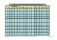
The <strong>Profibus</strong> <strong>DP</strong> Module (Mk2) has 10 possible configurations as indicated in the table. The default<br />
value is Configuration 1. The PLC must send a Check Configuration message during start up to<br />
confirm the Configuration to be used.<br />
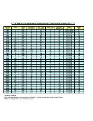
Configuration 1 2 3 4 5 6 7 8 9 10<br />
OUPUTS<br />
(16 Bits each)<br />
ACTCON <br />
POS_DV <br />
O_STAT <br />
PORTCM <br />
INPUTS<br />
(16 Bits each)<br />
IDATA1 & IDATA2 <br />
IDATA3 & IDATA4 <br />
TORQUE <br />
POSITN <br />
TEMPER <br />
ANALOG <br />
PORTST <br />
42 of 66 Publication S420E V3.0 Issue 01/05