Profibus Actuator Control Profibus DP Option Card Installation Manual
Profibus Actuator Control Profibus DP Option Card Installation Manual
Profibus Actuator Control Profibus DP Option Card Installation Manual
- No tags were found...

You also want an ePaper? Increase the reach of your titles
YUMPU automatically turns print PDFs into web optimized ePapers that Google loves.
<strong>Profibus</strong> <strong>DP</strong> Mk2 <strong>Option</strong> <strong>Card</strong> <strong>Installation</strong> <strong>Manual</strong><br />
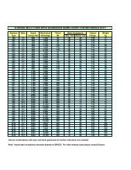
Parameter<br />
No.<br />
Description<br />
Value/Range<br />
9 Watchdog Timeout 0 – 255 sec<br />
0000 – 00FF hex<br />
10 Action on Loss of Comms 0 = Nothing (No Action)<br />
1 = Open<br />
3 = Close<br />
5 = Stop<br />
7 = Position<br />
Any other value = Off<br />
11 Comms Lost Position 0 – 100%<br />
0000 – 0064 hex<br />
12 Comms Fault Timer 0 – 255 sec<br />
0000 – 00FF hex<br />
13 Aux Input Mask 0 – 255<br />
0000 – 00FF hex<br />
14 ESD DI4/Net Disable DI-4 is ESD = 0 or 2<br />
and Data logger disable DI-4 is Net Disable = 1 or 3<br />
Data Logger is enabled = 0 or 1<br />
Data Logger is disabled = 2 or 4<br />
(Bit 0 = EDS/Net disable<br />
Bit 1 = data logger en/disable)<br />
15 Redundancy FR/SR mode Bit 0 : SR mode = 0, FR mode = 1<br />
and Simple/RedCom mode Bit 1 : Simple = 0, RedCom = 1<br />
16 Part Stroke position 1 – 99%<br />
0001 – 0063 hex<br />
17 Part Stroke Limit and timeout Bit 15 is 0 for close limit and 1 for open<br />
limit.<br />
Bits 0-14 are time values in seconds<br />
for timeout<br />
18 <strong>Actuator</strong> Type 0 – Don’t know (default)<br />
2 – A, AQ, Q,<br />
6 – IQ<br />
8 – IQT<br />
9 – EH<br />
10 – Skilmatic<br />
11 – Multiport<br />
Note:<br />
Default<br />
Value<br />
10 sec<br />
000A hex<br />
0 = Nothing<br />
(0000 hex)<br />
0%<br />
0000 hex<br />
255 sec<br />
00FF hex<br />
15<br />
000F hex<br />
ESD and<br />
Data<br />
Logger<br />
enabled<br />
0<br />
0000 hex<br />
0 <br />
0000 hex<br />
90<br />
005A hex<br />
Open and<br />
300 secs<br />
812C hex<br />
19 Reserved 0 0<br />
1 - Setting the deadband lower than the hysteresis, or the hysteresis greater than the<br />
deadband causes the hysteresis to be set to 0.1%<br />
2 - IQ Setting tool only allows 0.0 to 9.9% deadband to be set<br />
- On Redcom Dual Channel cards the default is 2 (0002 hex)<br />
These parameters set up the response the actuator will take to various control and network actions.<br />
There are three GSD files, one for a single channel card, one for a simple dual channel and one for a<br />
RedCom dual channel card. They all contain the same number of parameter settings.<br />
Single Channel <strong>Card</strong> GSD file RTRK0845<br />
Simple Dual Channel <strong>Card</strong> GSD file RTRC0845<br />
RedCom Dual Channel <strong>Card</strong> GSD file RTRR0845<br />
0<br />
50 of 66 Publication S420E V3.0 Issue 01/05