Profibus Actuator Control Profibus DP Option Card Installation Manual
Profibus Actuator Control Profibus DP Option Card Installation Manual
Profibus Actuator Control Profibus DP Option Card Installation Manual
- No tags were found...

Create successful ePaper yourself
Turn your PDF publications into a flip-book with our unique Google optimized e-Paper software.
<strong>Profibus</strong> <strong>DP</strong> Mk2 <strong>Option</strong> <strong>Card</strong> <strong>Installation</strong> <strong>Manual</strong><br />
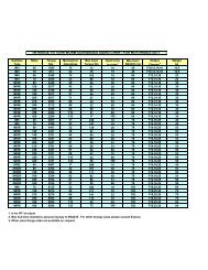
5.2 Digital Input Status Feedback<br />
The <strong>Profibus</strong> <strong>DP</strong> Module (Mk2) cyclically reports over the network a comprehensive data set relating<br />
to the status of the valve, actuator and card settings as indicated in the table below. The conventional<br />
contact indications are also available from the actuator limit switches and indication contacts.<br />
Register Name<br />
Status Feedback<br />
IQ IQT Q<br />
actuator actuator actuator<br />
IDATA1/0 Register 0 Bit 0 <strong>Actuator</strong> Moving <br />
IDATA1/1 Register 0 Bit 1 Close Limit <br />
IDATA1/2 Register 0 Bit 2 Open Limit <br />
IDATA1/3 Register 0 Bit 3 Running Closed <br />
IDATA1/4 Register 0 Bit 4 Running Open <br />
IDATA1/5 Register 0 Bit 5 Remote selected <br />
IDATA1/6 Register 0 Bit 6 Local Stop selected <br />
IDATA1/7 Register 0 Bit 7 Local selected <br />
IDATA2/0 Register 0 Bit 8 Thermostat Tripped <br />
IDATA2/1 Register 0 Bit 9 Monitor Relay <br />
IDATA2/2 Register 0 Bit 10 Valve Obstructed <br />
IDATA2/3 Register 0 Bit 11 Valve Jammed <br />
IDATA2/4 Register 0 Bit 12 Valve Moving by Hand <br />
IDATA2/5 Register 0 Bit 13 Moving Inhibited <br />
IDATA2/6 Register 0 Bit 14 Position <strong>Control</strong> Enabled <br />
IDATA2/7 Register 0 Bit 15 Watchdog Recovery <br />
IDATA3/0 Register 1 Bit 0 Battery Low <br />
IDATA3/1 Register 1 Bit 1 Open Interlock input <br />
IDATA3/2 Register 1 Bit 2 Close Interlock input <br />
IDATA3/3 Register 1 Bit 3 DI –1 <br />
IDATA3/4 Register 1 Bit 4 DI –2 <br />
IDATA3/5 Register 1 Bit 5 DI –3 <br />
IDATA3/6 Register 1 Bit 6 DI –4 <br />
IDATA3/7 Register 1 Bit 7 Slow Mode <br />
IDATA4/0 Register 1 Bit 8 GSD Configuration Permitted <br />
IDATA4/1 Register 1 Bit 9 Reserved <br />
IDATA4/2 Register 1 Bit 10 <strong>Control</strong> Contention <br />
IDATA4/3 Register 1 Bit 11 Partial Stroke in Progress <br />
IDATA4/4 Register 1 Bit 12 Part Stroke Error <br />
IDATA4/5 Register 1 Bit 13 Primary (0) or Backup (1) <br />
IDATA4/6 Register 1 Bit 14 1 or 2 Channels Available <br />
IDATA4/7 Register 1 Bit 15 SR (0) or FR (1) mode <br />
Note: 1 – This bit is reported when within the slow mode band, but does not affect the actuator.<br />
34 of 66 Publication S420E V3.0 Issue 01/05