P-Bus Gateway PBGW2.128
P-Bus Gateway PBGW2.128 - Persy
P-Bus Gateway PBGW2.128 - Persy
- No tags were found...

Create successful ePaper yourself
Turn your PDF publications into a flip-book with our unique Google optimized e-Paper software.
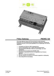
P-<strong>Bus</strong> <strong>Gateway</strong><br />
<strong>PBGW2.128</strong><br />
Universal gateway between the P-bus protocol and open standard<br />
protocols. The variety of available electrical interfaces on the gateway offers<br />
a wide range of possibilities for connections to various hardware.<br />
• Compatible with Siemens DDC equipment<br />
• 2 P-bus connections for a total of 128 load units<br />
• Standard RS-232, RS-485 and Ethernet connections for data exchange<br />
• Standard communication protocol Mod<strong>Bus</strong> RTU<br />
• Dynamic applicability by means of firmware upgrades<br />
• Many configuration possibilities<br />
• SD card interface for firmware upgrades and data-storage<br />
• DIN-rail mountable<br />
PCS0100en<br />
02.2008<br />
Persy Control Services B.V.<br />
Netherlands
Functions<br />
With the P-bus gateway the P-bus can be controlled and / or monitored by means<br />
of an universal data protocol. In this case the gateway also serves as a buffer for<br />
data traffic. All information send and received over P-bus is being stored in an<br />
internal buffer of the gateway. The same buffer can read and written to via RS-232,<br />
RS-485 or Ethernet.<br />
P-busses<br />
The P-bus is a 3-wire bus connection consisting of a PC-, PU- and PD-line. The<br />
system is composed of Siemens PTX rails and PTM I/O-modules. A detailed<br />
description can be found on the Siemens website under doc.no. N8022.<br />
One P-bus always consists of one master and one or more slaves. The gateway<br />
possesses 2 connections for P-bus which can be configured and controlled<br />
separately. There are 2 possible operating modes per P-bus connection:<br />
• Master Mode<br />
• Slave Mode<br />
In Master Mode the gateway will provide the P-bus of 24VDC power on the PU-line<br />
for the internal electronics in the slaves (I/O-modules). At the same time the bus<br />
will be polled on presence of slaves and data transfer from and to these slaves will<br />
be maintained by the gateway.<br />
In Slave Mode the gateway acts as a slave on the P-bus which is already being<br />
controlled by a master. For example this could be a Siemens DDC controller.<br />
The 24VDC on the PU-line already provided by the master is now being utilized by<br />
the gateway as a reference voltage for data transfer from and to the master. The<br />
gateway will present itself to the master as it were a slave (I/O-module).<br />
Communication<br />
Configuration<br />
Flexibility<br />
Data communication between the gateway and other equipment is provided by the<br />
international standardized data exchange protocol Mod<strong>Bus</strong> RTU. This could be<br />
peer-to-peer in the case of RS-232 or RS-485 as well as in a (ether-)network over<br />
TCP/IP.<br />
Depending on the firmware being present in the gateway other data exchange<br />
protocols are also possible.<br />
The gateway can be configured with the use of a standard HTML web browser via<br />
TCP/IP. Specialized computer software isn’t necessary. The configuration data is<br />
stored in a non-volatile memory of the gateway and is persistent in case of power<br />
failure or restart.<br />
The firmware in the gateway can be upgraded by means of a SD card. New<br />
firmware releases and applications will be made available for download on our<br />
website: www.persy.nl. The firmware can be stored on a SD card with a standard<br />
PC equipped with a SD card reader/writer or ordered directly and loaded into the<br />
gateway on-site. Therefore the P-bus <strong>Gateway</strong> stays an all-round, scalable and<br />
dynamic product with a great variety in fields of application.<br />
If desired, project specific firmware can be acquired to be able to adapt to your<br />
customers needs.<br />
2/12<br />
Persy Control Services B.V.<br />
Netherlands<br />
<strong>PBGW2.128</strong> – P-bus <strong>Gateway</strong><br />
PCS0100en<br />
02.2008
LED presentation<br />
LED Color Activity Meaning / problem solving<br />
Device 24VAC Green Permanently off<br />
No power available<br />
check power supply<br />
Permanently on Power available<br />
STATUS Red Permanently off Device functions properly<br />
Permanently on Hardware reset<br />
Blinking<br />
Hardware ready for firmware upgrade<br />
Fast Blinking<br />
Firmware upgrade in progress<br />
!! Do not switch off the device !!<br />
Slow Blinking<br />
Hardware failure<br />
In case of repeating failure after several<br />
attempts to restart, the gateway needs to<br />
be replaced<br />
P-BUS 1 / P-BUS 2 MASTER Green Permanently off<br />
P-bus functions in slave mode<br />
Reference voltage on PU-line is being<br />
utilized from the bus master<br />
Permanently on<br />
P-bus functions in master mode<br />
Reference voltage on PU-line is being<br />
provided by the P-bus <strong>Gateway</strong>.<br />
ACTIVITY Yellow Blinking Data transfer on the P-bus<br />
OVERLOAD Red Permanently off P-bus functions properly<br />
Permanently on<br />
Load units overflow on the P-bus<br />
Remove one or more slaves from the P-<br />
bus<br />
Blinking<br />
Short-circuit on the P-bus<br />
Check P-bus wiring<br />
RS-485 RxD Yellow Blinking Receives data<br />
TxD Yellow Blinking Transmits data<br />
RS-232 RxD Yellow Blinking Receives data<br />
TxD Yellow Blinking Transmits data<br />
ETHERNET LINK Green Permanently off No connection<br />
Permanently on Connection ready<br />
ACTIVITY Yellow Blinking Receives / transmits data packets<br />
Persy Control Services B.V.<br />
Netherlands<br />
<strong>PBGW2.128</strong> – P-bus <strong>Gateway</strong><br />
3/12<br />
PCS0100en<br />
02.2008
Disposal<br />
This device contains electric and electronic components and must not be disposed<br />
of with domestic waste. Printed circuit board and housing must be disposed of<br />
separately.<br />
The local and actual regulations must be observed.<br />
Technical data<br />
General device data<br />
Operational data<br />
Interface P-bus (2x)<br />
Interface RS-485<br />
Interface RS-232<br />
Interface Ethernet<br />
Operating voltage AC 24 V ± 10 %<br />
Safety extra-low voltage SELV<br />
Protective extra-low voltage PELV HD 384<br />
Frequency<br />
50/60 Hz<br />
Current consumption<br />
Max. 2 A<br />
Power consumption<br />
Data backup in case of power failure<br />
Configuration data (EEPROM)<br />
Polling cycle at I/O-modules<br />
Transmission speed<br />
Signal level<br />
Max. 45 VA<br />
> 10 years<br />
0,25 s<br />
62,5 KBaud<br />
Load units (1 l.u. = 12,5mA) Max. 64<br />
Maximum baud rate<br />
Protocol<br />
Galvanic isolation<br />
Maximum baud rate<br />
Protocol<br />
Flow control<br />
Interface type<br />
Bit rate<br />
Connector<br />
DC +23 V and 0 / –5 V<br />
115,2 KBaud<br />
Firmware dependent<br />
Yes<br />
115,2 KBaud<br />
Firmware dependent<br />
RTS/CTS (configurable)<br />
10BASE-T, IEEE 802.3 compatible<br />
10 MB/s<br />
RJ-45<br />
Interface SD card Slot type Standard SD card<br />
Dimensions<br />
24 x 32 x 2.1mm<br />
Plug-in screw terminals Power supply and signals Stranded or solid conductors,<br />
0,25 ... 2,5 mm² or 2 x 1,5 mm²<br />
Single cable lengths<br />
RS-485<br />
P-bus<br />
Cable length, special requirements<br />
Cross-section<br />
RS-485<br />
RS-232<br />
Cable type<br />
Ethernet<br />
Cable type<br />
Twisted-pair, stranded or solid<br />
conductors,<br />
2 x 1,0 mm² or Standard CAT5 UTP<br />
or STP<br />
Max. 50m<br />
Max. 200m<br />
Min. 3 x 0.75 mm²<br />
Max. 30 m<br />
Max. 3 m<br />
9-core standard screened cable<br />
Max. 100 m<br />
Standard CAT5 UTP<br />
4/12<br />
Persy Control Services B.V.<br />
Netherlands<br />
<strong>PBGW2.128</strong> – P-bus <strong>Gateway</strong><br />
PCS0100en<br />
02.2008
Housing protection<br />
standard<br />
Protection standard to EN 60529<br />
Ambient conditions Operation Class 3K5 to IEC 721<br />
Temperature 0 ... 50 °C<br />
Humidity<br />
< 85 % rh<br />
Industry standards<br />
Dimensions<br />
IP30<br />
Transport Class 2K3 to IEC 721<br />
Temperature – 25 ... 65 °C<br />
Humidity<br />
< 95 % rh<br />
Product safety<br />
Automatic electronic controls for<br />
household and similar use EN 60730-1<br />
Electromagnetic compatibility<br />
For use in residential, commercial<br />
and light industrial premises<br />
Interference immunity EN 50082-1<br />
Emitted interference EN 50081-1<br />
Meets the requirements for CE marking:<br />
Electromagnetic compatibility<br />
Low Voltage Directive<br />
See “Dimensions”<br />
89/336/EEG<br />
73/23/EEG<br />
Weight Including packaging Approx. 600 g<br />
Persy Control Services B.V.<br />
Netherlands<br />
<strong>PBGW2.128</strong> – P-bus <strong>Gateway</strong><br />
5/12<br />
PCS0100en<br />
02.2008
Connection terminals<br />
Pin layout<br />
Pin Code Description<br />
X1 Power supply<br />
1 G AC 24V Phase<br />
2 G0 AC 24V Neutral<br />
X2 P-bus 1<br />
X3 P-bus 2<br />
X4 RS-485<br />
1 PC Synchronization line (clock)<br />
2 PU Reference voltage<br />
3 PD Data line<br />
1 PC Synchronization line (clock)<br />
2 PU Reference voltage<br />
3 PD Data line<br />
1 A Data A<br />
2 B Data B<br />
3 C Shielding (common)<br />
Notes • The wires of the same twisted pair must be connected<br />
to the A and B terminals<br />
• Screening is not usually necessary<br />
X5 RS-232<br />
X6 Ethernet<br />
1 NC Not Connected<br />
2 TxD Transmit Data<br />
3 RxD Receive Data<br />
4 NC Not Connected<br />
5 SGND Signal Ground<br />
6 NC Not Connected<br />
7 CTS Clear To Send<br />
8 RTS Request To Send<br />
9 NC Not Connected<br />
1 TD+ Transmit Data +<br />
2 TD- Transmit Data -<br />
3 RD+ Receive Data +<br />
4 NC Not Connected<br />
5 NC Not Connected<br />
6 RD- Receive Data -<br />
7 NC Not Connected<br />
8 NC Not Connected<br />
6/12<br />
Persy Control Services B.V.<br />
Netherlands<br />
<strong>PBGW2.128</strong> – P-bus <strong>Gateway</strong><br />
PCS0100en<br />
02.2008
Dimensions<br />
all dimensions in mm<br />
Persy Control Services B.V.<br />
Netherlands<br />
<strong>PBGW2.128</strong> – P-bus <strong>Gateway</strong><br />
7/12<br />
PCS0100en<br />
02.2008
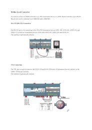
Connection diagrams<br />
P-bus control with universal DDC-Controller<br />
In this configuration it is possible to control the P-bus (I/O-modules) with an universal<br />
DDC-controller. The electrical connection between the gateway and the DDCcontroller<br />
can be established over RS-232, RS-485 or Ethernet. The gateway acts in<br />
this case as a transparent connection between the DDC-controller and the P-bus I/O<br />
modules.<br />
8/12<br />
Persy Control Services B.V.<br />
Netherlands<br />
<strong>PBGW2.128</strong> – P-bus <strong>Gateway</strong><br />
PCS0100en<br />
02.2008
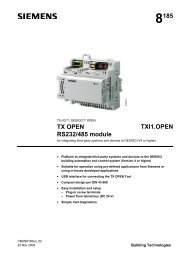
Data exchange between DDC-controllers over P-bus (with gateway)<br />
In this configuration data exchange is possible between two DDC-systems of different<br />
brand over P-bus. The gateway acts in this case as a transparent connection between<br />
the two DDC-controllers. Each controller manages its own P-bus I/O modules and<br />
therefore its own processes. In complementary to this, the gateway creates<br />
(configurable) “virtual” I/O-modules in order to virtually connect the two DDCcontrollers.<br />
The virtual I/O-modules behave as if they were tied to each other on<br />
hardware level (see next connection diagram without gateway).<br />
Persy Control Services B.V.<br />
Netherlands<br />
<strong>PBGW2.128</strong> – P-bus <strong>Gateway</strong><br />
9/12<br />
PCS0100en<br />
02.2008
Data exchange between DDC-controllers over P-bus (without gateway)<br />
10/12<br />
Persy Control Services B.V.<br />
Netherlands<br />
<strong>PBGW2.128</strong> – P-bus <strong>Gateway</strong><br />
PCS0100en<br />
02.2008
Remote I/O over Ethernet TCP / IP<br />
In this configuration it is possible to control a process remotely over Ethernet. The<br />
DDC controller is being placed in control cabinet 1a for example and controls a<br />
process locally over P-bus. The combination of 2 gateways connected via TCP / IP<br />
extends this P-bus to control cabinet 1b from where another process is being<br />
controlled.<br />
Persy Control Services B.V.<br />
Netherlands<br />
<strong>PBGW2.128</strong> – P-bus <strong>Gateway</strong><br />
11/12<br />
PCS0100en<br />
02.2008
I/O monitoring<br />
In this configuration it is possible to monitor processes over P-bus. All signals from and<br />
to the DDC-controller are being monitored by the gateway and can be readout /<br />
visualized with a remote protocol.<br />
© 2008 Persy Control Services B.V.<br />
www.persy.nl<br />
Subject to changes<br />
12/12<br />
Persy Control Services B.V.<br />
Netherlands<br />
<strong>PBGW2.128</strong> – P-bus <strong>Gateway</strong><br />
PCS0100en<br />
02.2008