PXM20-E Operator unit Data sheet N9234en - Persy
PXM20-E Operator unit Data sheet N9234en - Persy
PXM20-E Operator unit Data sheet N9234en - Persy
- No tags were found...

Create successful ePaper yourself
Turn your PDF publications into a flip-book with our unique Google optimized e-Paper software.
9 234<br />
DESIGO PX<br />
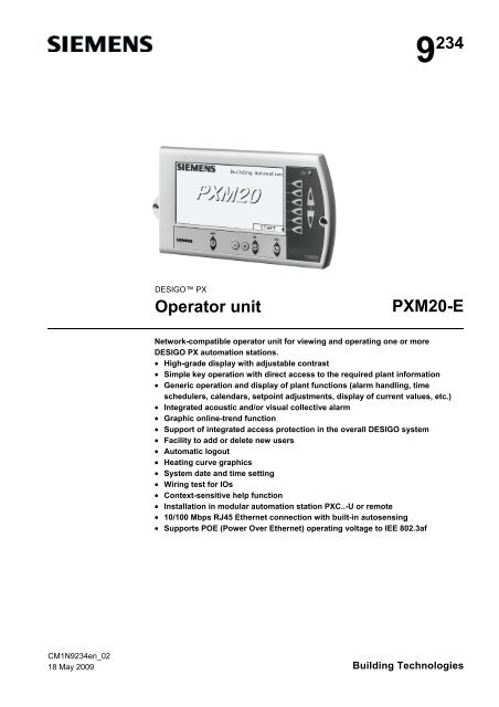
<strong>Operator</strong> <strong>unit</strong><br />
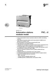
<strong>PXM20</strong>-E<br />
Network-compatible operator <strong>unit</strong> for viewing and operating one or more<br />
DESIGO PX automation stations.<br />
• High-grade display with adjustable contrast<br />
• Simple key operation with direct access to the required plant information<br />
• Generic operation and display of plant functions (alarm handling, time<br />
schedulers, calendars, setpoint adjustments, display of current values, etc.)<br />
• Integrated acoustic and/or visual collective alarm<br />
• Graphic online-trend function<br />
• Support of integrated access protection in the overall DESIGO system<br />
• Facility to add or delete new users<br />
• Automatic logout<br />
• Heating curve graphics<br />
• System date and time setting<br />
• Wiring test for IOs<br />
• Context-sensitive help function<br />
• Installation in modular automation station PXC..-U or remote<br />
• 10/100 Mbps RJ45 Ethernet connection with built-in autosensing<br />
• Supports POE (Power Over Ethernet) operating voltage to IEE 802.3af<br />
CM1<strong>N9234en</strong>_02<br />
18 May 2009 Building Technologies
Application<br />
The <strong>PXM20</strong>-E operator <strong>unit</strong> ensures the convenient display and operation of DESIGO<br />
PX automation stations via BACnet network communication. The graphics-based<br />
display with clear text and direct access via the keyboard ensure a most user-friendly<br />
operation.<br />
Functions<br />
All values visible in the system can be displayed in accordance with the defined<br />
operator profile. Typical displays:<br />
• Display of current values<br />
• Setpoint and parameter settings<br />
• Maintenance and error messages<br />
• Alarm lists and single alarm messages with acknowledgement option and/or reset<br />
• Time schedulers (7-day schedules and exception programs)<br />
• Plant switching<br />
• Login and password inputs<br />
An integrated collective alarm message system with acoustic and visual indication is<br />
provided.<br />
Operating concept<br />
User's guide<br />
As the <strong>PXM20</strong>-E operator <strong>unit</strong> is designed for end-user operation the operating concept<br />
concentrates on the simplest and clearest possible display following intuitive operating<br />
principles rather then displaying as many values as possible.<br />
• Any text is displayed as clear text in the chosen language.<br />
• To ensure a clear orientation for any operator the two top display lines (header lines)<br />
always show which building services system or which function is currently in<br />
operation.<br />
• The basic concept of the operation ensures that it is always possible to select direct,<br />
with the click of a button on the keyboard, the plant information shown on the<br />
relevant line (direct access keys).<br />
• Any settings or modifications (for example in graphics) can be followed direct on the<br />
display (e.g. graphics display for scheduler).<br />
• The basic concept also ensures that all information and help functions can be called<br />
up any time (info key).<br />
The functions of the <strong>PXM20</strong>-E are described in detail in the User's guide,<br />
DESIGO V2.35, <strong>PXM20</strong>/<strong>PXM20</strong>-E operator <strong>unit</strong>, document CM110754.<br />
Indicators and operator<br />
controls<br />
1<br />
2<br />
00262<br />
3<br />
4<br />
OK<br />
ESC<br />
? – +<br />
<strong>PXM20</strong><br />
7 5 6<br />
2/8<br />
Siemens <strong>Operator</strong> <strong>unit</strong> <strong>PXM20</strong>-E CM1<strong>N9234en</strong>_02<br />
Building Technologies 18 May 2009
1. Display<br />
2. Navigation keys (direct access keys and PageUp/PageDown keys):<br />
The direct access keys allow direct access to the relevant line. Possible functions:<br />
– Select value and start the value adjustment<br />
– Confirm new value<br />
– Start function<br />
– Open item<br />
3. Alarm LED: The alarm LED lights up or flashes if an alarm is present in the system.<br />
4. The PageUp and PageDown keys are provided for page scrolling if a page contains more values<br />
than can be shown on the display at the same time.<br />
5. Edit keys: These keys allow the selected values to be modified ( and ) and confirmed ().<br />
6. ESC key (Undo and GoUp): When editing a value the editing process can be cancelled by using the<br />
Undo key (previous value will be displayed again). Otherwise the GoUp key selects the hierarchically<br />
higher object.<br />
This key is placed between the two blocks containing the navigation and editing keys because,<br />
according to its function, it belongs to both.<br />
7. Info key: This key selects the information mode for the next keyboard click.<br />
Generic operation and<br />
display<br />
Depending on to the application program each menu tree is different. Navigation<br />
through the menu tree is based on the "ClickDown" procedure using the navigation<br />
keys.<br />
Alarms and events<br />
If the <strong>PXM20</strong>-E receives an alarm or an event appears on the display a pop-op window<br />
appears with the relevant information.<br />
Visual and acoustic<br />
alarm<br />
When an alarm is present the alarm LED flashes and changes to steady light when all<br />
alarms have been acknowledged. The acoustic alarm is provided as an option and can<br />
be activated optionally when an alarm is triggered.<br />
Alarm Viewer<br />
Alarms are written into the Alarm Viewer with a symbol, a description and a time/date<br />
stamp in chronological order. An acknowledgement mask to acknowledge alarms can<br />
be called up in the Alarm Viewer . After acknowledgement the alarm entry disappears<br />
from the Alarm Viewer ; however, it will continue to be saved in the history list. Further<br />
details can be viewed in the alarm history (e.g. out of service, overridden, dead band,<br />
present value, etc.)<br />
The <strong>PXM20</strong>-E history can contain max. 50 entries; the older ones are deleted.<br />
Scheduler<br />
The Scheduler allows the user a time-dependent switch on/off and the programming of<br />
time-dependent setpoint adjustments.<br />
The Scheduler consists of a 7-day schedule and an exception program.<br />
7-day schedule<br />
With the help of the navigation and editing<br />
keys it is very simple to create, modify, delete<br />
or copy a 7-day schedule in this mask. For<br />
each day an individual "road map" is<br />
programmed.<br />
Exception programs<br />
If the field EXCEPTION OVERVIEW is clicked<br />
in the 7-day schedule (see above) the current<br />
monthly overview appears and shows as<br />
inverted all the days which are affected by an<br />
exception. All other months can be called up<br />
as overview by using the top direct access<br />
key.<br />
Siemens <strong>Operator</strong> <strong>unit</strong> <strong>PXM20</strong>-E CM1<strong>N9234en</strong>_02<br />
Building Technologies 18 May 2009<br />
3/8
In the exception program, too, the exceptions are created, modified or deleted by using<br />
the navigation and editing keys. It is possible to define exception days (e.g. a bank<br />
holiday) as well as exception periods (e.g. holiday periods).<br />
Click the EXCEPTIONS field to display a list of all programmed exceptions.<br />
Online trend<br />
The <strong>PXM20</strong>-E operator <strong>unit</strong> provides the user with five channels for trend logging,<br />
enabling 5 data points to be logged.<br />
There are three separate ways of viewing the trend data:<br />
• Graphical view: In this view all the values of a trend data point stored in <strong>PXM20</strong>-E<br />
will be displayed graphically<br />
• Online graphical view: In the online view the values will be displayed in a graphical<br />
and dynamic manner, i.e. in real time.<br />
• List: In place of a graphic view, the values can be displayed in list form<br />
Info concept<br />
Access protection<br />
Auto logout<br />
and sleep mode<br />
Language versions<br />
Press the info key to switch to info mode. In this info mode two different kinds of<br />
information can be called up:<br />
• Pressing the info key a second time displays general information for the currently<br />
displayed object (e.g. complete path, clear text of object).<br />
• Pressing a direct access key in info mode displays information for the object or value<br />
on the selected line.<br />
Exit the info mode by pressing any key.<br />
• Login by entering password with string editor<br />
• Display and operation in accordance with user privileges<br />
• Definition of user privileges during engineering of DESIGO PX configurations<br />
• Login always referenced to a site<br />
• Wiring test possible without login<br />
• Alarms<br />
– Alarm display depends on user privilege<br />
– Alarm handling in accordance with user privileges<br />
• Logout<br />
If no operator activities are carried out within a set period the device switches off<br />
automatically and the display is turned off.<br />
Pressing any key activates the device automatically again and the background lighting<br />
of the display is switched on.<br />
When the operator <strong>unit</strong> is delivered the language is set to English. The language setting<br />
can be changed internally.<br />
4/8<br />
Siemens <strong>Operator</strong> <strong>unit</strong> <strong>PXM20</strong>-E CM1<strong>N9234en</strong>_02<br />
Building Technologies 18 May 2009
Ordering<br />
1 <strong>PXM20</strong>-E operator <strong>unit</strong><br />
Compatibility<br />
Device Type <strong>Data</strong> <strong>sheet</strong><br />
Modular automation stations PXC...-U 9221<br />
Compact automation stations PXC....E-D N9215<br />
Modular automation stations PXC....E-D N9222<br />
Accessories<br />
Description<br />
Connection cable, length 3.0 m (order separately)<br />
Adapter cableRS232 – RJ45 to connect a PXA-C1 to a PC (order separately)<br />
Adapter on <strong>PXM20</strong>-E for firmware download (order separately)<br />
Mounting frame for mounting on the wall or on the control panel door (order separately)<br />
Type<br />
PXA-C1<br />
PXA-C2<br />
PXA-C4<br />
PXA-H1<br />
Design<br />
The <strong>PXM20</strong>-E operator <strong>unit</strong> is contained in a robust plastic housing, ideally suited for its<br />
many different mounting methods.<br />
All indicators and controls are mounted on the front cover of the <strong>unit</strong> (see page 2).<br />
The connections for the automation stations are incorporated on the back of the <strong>unit</strong><br />
(see page 7).<br />
Mounting instructions<br />
The <strong>PXM20</strong>-E is suitable for control panel front mounting or vertical panels (e.g. remote<br />
operating panels or similar <strong>unit</strong>s). The <strong>unit</strong> is also suitable for DIN rail snap-mounting.<br />
In addition, the <strong>PXM20</strong>-E can be mounted direct on any modular automation station.<br />
The required Ethernet network connection is an anti-kink cable which can be introduced<br />
through an aperture in the modular automation station.<br />
Commissioning<br />
Wiring test<br />
Switchless<br />
commissioning<br />
Firmware download<br />
When using network-compatible <strong>PXM20</strong>-E <strong>unit</strong>s it is possible to carry out a wiring test<br />
of the connected field devices even without a loaded application program. The field<br />
devices are shown with the current value and <strong>unit</strong>.<br />
Commissioning before programming:<br />
The wiring test supports the reading of all I/Os of compact automation stations, and<br />
modular – as long as the modules have an address key. In addition the wiring test<br />
supports writing to all outputs. This means you can switch on fans, pumps, lamps etc.,<br />
or drive valves to a defined position.<br />
The outputs keep their state as long as the automation station is powered.<br />
It is possible to download firmware via FTP.<br />
Siemens <strong>Operator</strong> <strong>unit</strong> <strong>PXM20</strong>-E CM1<strong>N9234en</strong>_02<br />
Building Technologies 18 May 2009<br />
5/8
Disposal<br />
The device is classified as waste electronic equipment in terms of the European<br />
Directive 2002/96/EC (WEEE) and should not be disposed of as unsorted municipal<br />
waste.<br />
The relevant national legal rules are to be adhered to.<br />
Regarding disposal, use the systems setup for collecting electronic waste.<br />
Observe all local and applicable laws.<br />
Technical data<br />
General device data Operating voltage for 2-pin connector AC 24 V ± 20 % or<br />
DC min. 12 V ... max. 40 V<br />
Operating voltage when plugged into<br />
modular automation station<br />
AC 24 V ± 20 %, derived automatically<br />
from modular automation station<br />
Electrical voltage via Ethernet connection Power Over Ethernet (POE)<br />
to IEEE 802.3af<br />
Safety extra low voltage SELV<br />
Protective extra low voltage PELV HD 384<br />
Frequency<br />
50/60 Hz<br />
Power consumption AC 24 V max. 9 VA<br />
DC 12 ... 40 V max. 5 W<br />
Internal fuse<br />
Thermal, self-resetting<br />
Operating data Main processor Freescale PowerPC<br />
<strong>Data</strong> backup in case of power failure<br />
Applications, parameter (FLASH)<br />
> 10 years<br />
Keyboard Type Keyboard with plastic membrane and<br />
pressure point<br />
Key area<br />
7 x 7 mm<br />
Switching pressure<br />
2.1 N<br />
Travel<br />
0.6 ... 0.7 mm<br />
Operating life<br />
> 1 million operations<br />
Material, front membrane<br />
Polycarbonate<br />
Material, contacts<br />
Conductive silver,<br />
snap-on discs gold-plated<br />
Display<br />
Mechanical<br />
LCD display<br />
F-STN, Black & White<br />
Display area<br />
123 x 68 mm<br />
No. of dots<br />
240 x 128 dots<br />
Dot size<br />
0.47 x 0.47 mm<br />
Dot area<br />
0.50 x 0.50 mm<br />
Optical<br />
Contrast ratio 20: 1<br />
Brightness 60.0 cd/m 2<br />
Viewing angle ± 40°<br />
Viewing direction<br />
6 o'clock<br />
Background lighting<br />
CCFL (cold cathode fluorescent lamp)<br />
Rise time lamp<br />
5 min = 80 % brightness<br />
Life time lamp<br />
20,000 operating hours<br />
= 64 % brightness<br />
6/8<br />
Siemens <strong>Operator</strong> <strong>unit</strong> <strong>PXM20</strong>-E CM1<strong>N9234en</strong>_02<br />
Building Technologies 18 May 2009
Ethernet interface Network 10Base-T/100Base-TX, with built-in<br />
auto-sensing<br />
Cable Min. Cat 5, shielded if >3m<br />
PHY<br />
Auto-MDI/MDIX crossover correction<br />
Power supply via Ethernet connection Supports POE (Power Over Ethernet)<br />
to IEE 802.3af<br />
Green LED<br />
Ethernet Link OK<br />
Orange LED<br />
Ethernet Signal TX<br />
Protocol<br />
BACnet over IP<br />
Buzzer Noise level at 10 cm distance Min. 85dBA<br />
Frequency<br />
2300 ± 300 Hz<br />
Mounting options<br />
– For control panel mounting, remote operating panels, etc.<br />
– DIN rail mounting<br />
– Direct on modular automation stations<br />
Connections see page 7<br />
Housing protection standard Protection standard to EN 60529 IP 40 (built-in), else IP 30<br />
Protection class Insulation protection class III<br />
Ambient conditions Operation Class 3K5 to IEC 721<br />
Temperature 0 ... 45 °C<br />
Humidity<br />
< 85 % rh<br />
Transport Class 2K3 to IEC 721<br />
Temperature – 20 ... 60 °C 1)<br />
Humidity<br />
< 85 % rh<br />
Industry standards<br />
Product safety<br />
Automatic electronic controls for<br />
household and similar use EN 60730-1<br />
Special requirements for energy controllers EN 60730-2-11<br />
Electromagnetic compatibility<br />
Interference imm<strong>unit</strong>y<br />
EN 61000-6-2 industrial<br />
Emitted interference<br />
EN 61000-6-3 residential<br />
Meets requirements for CE marking:<br />
Electromagnetic compatibility<br />
2004/108/EC<br />
UL-Approbation<br />
UL 916: PAZX, PAZX7<br />
Environmental compatibility<br />
The product environmental declaration<br />
CA1E9234 contains data on environmentally<br />
compatible product design and assessments<br />
(RoHS compliance, materials composition,<br />
packaging, environmental benefit, disposal)<br />
ISO 14001 (Environment)<br />
ISO 9001 (Quality)<br />
SN 36350 (Environmentally<br />
compatible products)<br />
2002/95/EC (RoHS)<br />
Dimensions 117 x 210 x 37 mm (H x W x D) See “Dimensions”, page 7<br />
1) Background color changes slightly depending on ambient temperature. This phenomenon is<br />
reversible.<br />
Siemens <strong>Operator</strong> <strong>unit</strong> <strong>PXM20</strong>-E CM1<strong>N9234en</strong>_02<br />
Building Technologies 18 May 2009<br />
7/8
Connections<br />
00264<br />
RJ45 socket<br />
for Ethernet connection<br />
1<br />
G0 (GND -)<br />
2<br />
G (Plus +)<br />
Pin1 I 2<br />
Plug-in connection for<br />
modular automation stations PXC…-U<br />
Dimensions<br />
All dimensions in mm<br />
00342<br />
00343<br />
117<br />
210<br />
37<br />
Drill and cut-out<br />
template<br />
5.6 176.8<br />
11.6<br />
00267<br />
47.4<br />
ø 4.8<br />
64.6<br />
8/8<br />
© 2005 - 2009 Siemens Switzerland Ltd. Subject to changes<br />
Siemens <strong>Operator</strong> <strong>unit</strong> <strong>PXM20</strong>-E CM1<strong>N9234en</strong>_02<br />
Building Technologies 18 May 2009