Roller Roman Fabrication
Roller Roman Fabrication - AV Outlet
Roller Roman Fabrication - AV Outlet
- No tags were found...

Create successful ePaper yourself
Turn your PDF publications into a flip-book with our unique Google optimized e-Paper software.
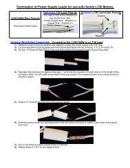
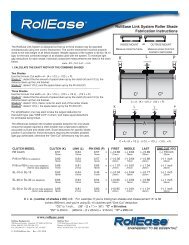
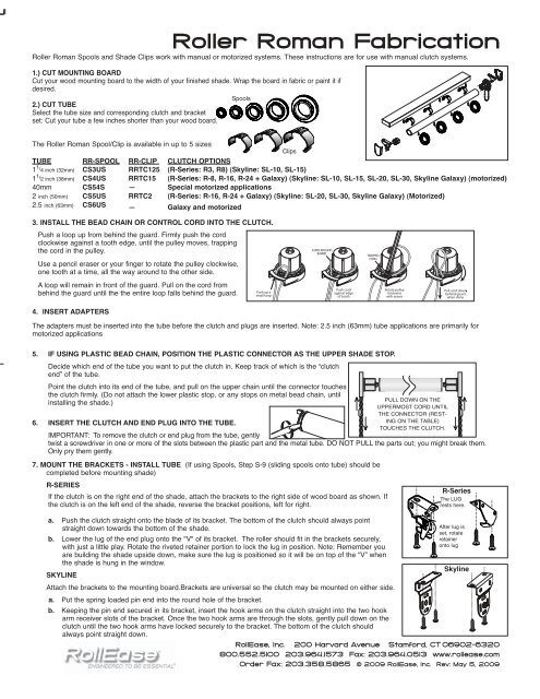
<strong>Roller</strong> <strong>Roman</strong> Spools and Shade Clips work with manual or motorized systems. These instructions are for use with manual clutch systems.<br />
1.) CUT MOUNTING BOARD<br />
Cut your wood mounting board to the width of your finished shade. Wrap the board in fabric or paint it if<br />
desired.<br />
2.) CUT TUBE<br />
Select the tube size and corresponding clutch and bracket<br />
set: Cut your tube a few inches shorter than your wood board.<br />
<strong>Roller</strong> <strong>Roman</strong> <strong>Fabrication</strong><br />
Spools<br />
The <strong>Roller</strong> <strong>Roman</strong> Spool/Clip is available in up to 5 sizes<br />
Clips<br />
TUBE RR-SPOOL RR-CLIP CLUTCH OPTIONS<br />
1 1 / 4 inch (32mm) CS3US RRTC125 (R-Series: R3, R8) (Skyline: SL-10, SL-15)<br />
1 1 / 2 inch (38mm) CS4US RRTC15 (R-Series: R-8, R-16, R-24 + Galaxy) (Skyline: SL-10, SL-15, SL-20, SL-30, Skyline Galaxy) (motorized)<br />
40mm CS54S — Special motorized applications<br />
2 inch (50mm) CS5US RRTC2 (R-Series: R-16, R-24 + Galaxy) (Skyline: SL-20, SL-30, Skyline Galaxy) (Motorized)<br />
2.5 inch (63mm) CS6US — Galaxy and motorized<br />
3. INSTALL THE BEAD CHAIN OR CONTROL CORD INTO THE CLUTCH.<br />
Push a loop up from behind the guard. Firmly push the cord<br />
clockwise against a tooth edge, until the pulley moves, trapping<br />
the cord in the pulley.<br />
Use a pencil eraser or your finger to rotate the pulley clockwise,<br />
one tooth at a time, all the way around to the other side.<br />
A loop will remain in front of the guard. Pull on the cord from<br />
behind the guard until the the entire loop falls behind the guard.<br />
4. INSERT ADAPTERS<br />
The adapters must be inserted into the tube before the clutch and plugs are inserted. Note: 2.5 inch (63mm) tube applications are primarily for<br />
motorized applications<br />
5. IF USING PLASTIC BEAD CHAIN, POSITION THE PLASTIC CONNECTOR AS THE UPPER SHADE STOP.<br />
Decide which end of the tube you want to put the clutch in. Keep track of which is the “clutch<br />
end” of the tube.<br />
Point the clutch into its end of the tube, and pull on the upper chain until the connector touches<br />
the clutch firmly. (Do not attach the lower plastic stop, or any stops on metal bead chain, until<br />
installing the shade.)<br />
6. INSERT THE CLUTCH AND END PLUG INTO THE TUBE.<br />
PULL DOWN ON THE<br />
UPPERMOST CORD UNTIL<br />
THE CONNECTOR (REST-<br />
ING ON THE TABLE)<br />
TOUCHES THE CLUTCH.<br />
IMPORTANT: To remove the clutch or end plug from the tube, gently<br />
twist a screwdriver in one or more of the slots between the plastic part and the metal tube. DO NOT PULL the parts out; you might break them.<br />
Only pry them gently.<br />
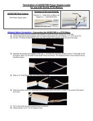
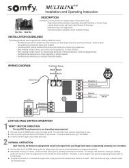
7. MOUNT THE BRACKETS - INSTALL TUBE (If using Spools, Step S-9 (sliding spools onto tube) should be<br />
completed before mounting shade)<br />
R-SERIES<br />
If the clutch is on the right end of the shade, attach the brackets to the right side of wood board as shown. If<br />
the clutch is on the left end of the shade, reverse the bracket positions, left for right.<br />
a. Push the clutch straight onto the blade of its bracket. The bottom of the clutch should always point<br />
straight down towards the bottom of the shade.<br />
b. Lower the lug of the end plug onto the "V" of its bracket. The roller should fit in the brackets securely,<br />
with just a little play. Rotate the riveted retainer portion to lock the lug in position. Note: Remember you<br />
are building the shade upside down, make sure the lug is positioned so it will be on top of the “V” when<br />
the shade is hung in the window.<br />
SKYLINE<br />
Attach the brackets to the mounting board.Brackets are universal so the clutch may be mounted on either side.<br />
a. Put the spring loaded pin end into the round hole of the bracket.<br />
b. Keeping the pin end secured in its bracket, insert the hook arms on the clutch straight into the two hook<br />
arm receiver slots of the bracket. Once the two hook arms are through the slots, gently pull down on the<br />
clutch until the two hook arms have locked securely to the bracket. The bottom of the clutch should<br />
always point straight down.<br />
R-Series<br />
The LUG<br />
rests here.<br />
After lug is<br />
set, rotate<br />
retainer<br />
onto lug<br />
Skyline<br />
RollEase, Inc. 200 Harvard Avenue Stamford, CT 06902-6320<br />
800.552.5100 203.964.1573 Fax: 203.964.0513 www.rollease.com<br />
Order Fax: 203.358.5865 © 2009 RollEase, Inc. Rev: May 5, 2009
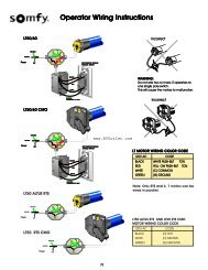
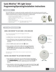
SPOOLS (if using Clips, go on to step C-8)<br />
S-8.) INSTALL SCREW EYES<br />
Install one screw eye for each lift line to the wood mounting board.<br />
Mount the screw eye on the edge of the mounting board that the shade<br />
fabric will be attached to. The screw eyes should be in line with the<br />
rings on your shade. All lift lines must be routed through a screw eye<br />
before attaching to the RR Spool unless your shade does not have any<br />
edge lifts, then you may route ribbon/lift line directly to the spool<br />
bypassing use of screw eyes.<br />
<strong>Roller</strong> <strong>Roman</strong> <strong>Fabrication</strong><br />
S-9.) ATTACH SPOOLS<br />
Slide one spool onto the tube per lift line. Align each spool directly so<br />
each spool is centered left/right over the screw eye and shade rings.. Screw the spool set-screw into the tube ensuring sure each spool is aligned in the<br />
same orientation as the other spools. The lift line knot holes should be positioned all on the the same side of the tube.<br />
S-10.) ATTACH RIBBON TAPE or LIFT LINE<br />
The length of the ribbon-tape or lift line must equal the length of the shade plus 6 inches. Direct the ribbon/line from the screw eye down to the spool<br />
and through the inside opening of the spool knot hole. On the outside of the spool, tie a double or triple knot that is large enough so it can not pull<br />
back through the knot hole. If the shade has no edge lifts, it is permissible to route the lift line directly to the spool and by-pass the use of any screw<br />
eyes.<br />
(go on to Step 12)<br />
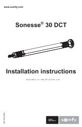
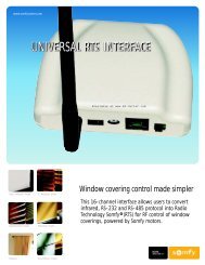
CLIPS<br />
C-8.) INSTALL SCREW EYES<br />
Install one screw eye for each lift line to the wood mounting board.<br />
Mount the screw eye on the edge of the mounting board that the shade<br />
fabric will be attached to. The screw eyes should be in line with the<br />
rings on your shade. All lift lines must be routed through a screw eye<br />
before attaching to the RR Clip.<br />
1 2 3 4 5<br />
C-9.) MARK TUBE<br />
Mark the tube 3 inches to the left or right of the screw eye. (IMPOR-<br />
TANT…Each clip must be equidistant from the screw eye).<br />
The clips will be mounted to the left of the screw eye and some to the<br />
right of the screw eye. Alternate the position of first clip on the left<br />
side and the second clip on the right... alternating left and right across<br />
all lift lines. Do not place all the clips on the same side of the screw<br />
eye, this may encourage the shade to creep left or right when raised<br />
as the lift line spools and the take-up angle changes. When the clips<br />
are placed on alternating opposing sides it tends to neutralize any<br />
creeping effect.<br />
C-10.) ATTACH CLIPS<br />
Based on the tube size selected choose the correct size RR Clip.<br />
Once the Clip is attached to the tube it will not slip or pop off<br />
of the tube. Note: You may insert a screw driver underneath the clip<br />
and lift slightly for small adjustments in positioning. Clips can be<br />
attached at this point or it can be pre-corded and then attached.<br />
C-11.) ATTACH LIFT LINE<br />
The length of the lift line must equal the length of the shade plus 6 inches. Direct the line from the screw eye to the clip down through the appropriate<br />
size opening (depending on cord diameter) Tie with a knot that is large enough so it can not pull through and use a triple knot to secure. There are 2<br />
holes at the top of the clip. The smaller opening accommodates up to 1.4mm cord. The larger opening accommodates up to 2.0mm cord.<br />
12.) INSTALL THE TENSION DEVICE<br />
See tension device assembly sheet for details<br />
RollEase, Inc. 200 Harvard Avenue Stamford, CT 06902-6320<br />
800.552.5100 203.964.1573 Fax: 203.964.0513 www.rollease.com<br />
Order Fax: 203.358.5865 © 2009 RollEase, Inc. Rev: May 5, 2009