Tiger Spas
2003 - All Seasons Spa
2003 - All Seasons Spa
Create successful ePaper yourself
Turn your PDF publications into a flip-book with our unique Google optimized e-Paper software.
Once your spa has been filled with water, turn it on and test all of the circuit breakers.<br />
NOTE: If both breakers immediately trip, verify that the #10 AWG WHITE neutral wire is connected from TB-1 terminal 5 to the N (load neutral)<br />
terminal of the 30 amp subpanel breaker. Each breaker should be tested prior to each use. Here’s how:<br />
1. Push the “TEST” button on each GFCI breaker, and observe it click OFF.<br />
2. Wait 30 seconds, then push the breaker switch to the OFF (down) position (to ensure that it has completely disengaged), then push the<br />
breaker switch to the ON (up) position. If you don't wait 30 seconds, the spa’s control panel may flash four lines on and off – try again.<br />
If any of the GFCI breakers fails to operate in this manner, your spa may have an electrical malfunction, and you may be at risk of electrical shock.<br />
Turn off all circuits and do not use the spa until the problem has been corrected by an authorized service agent.<br />
WARNING: Removing or bypassing any GFCI breaker will result in an unsafe spa and will void the spa’s warranty.<br />
IMPORTANT: Should you ever find the need to move or relocate your <strong>Tiger</strong> River ® spa, it is essential that you understand and apply these<br />
installation requirements. Your Caldera spa has been carefully engineered to provide maximum safety against electric shock. Remember,<br />
connecting the spa to an improperly wired circuit will negate many of its safety features.<br />
NOTE: Long wiring runs may require larger-gauge wire than stated.<br />
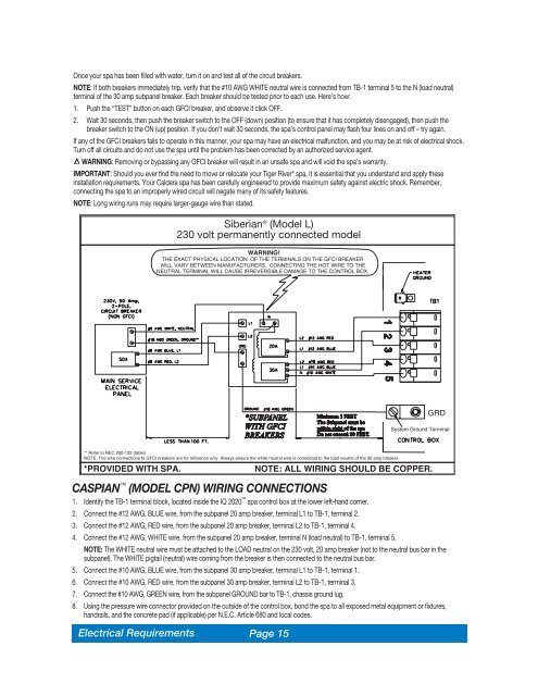
Siberian ® (Model L)<br />
230 volt permanently connected model<br />
WARNING!<br />
THE EXACT PHYSICAL LOCATION OF THE TERMINALS ON THE GFCI BREAKER<br />
WILL VARY BETWEEN MANUFACTURERS. CONNECTING THE HOT WIRE TO THE<br />
NEUTRAL TERMINAL WILL CAUSE IRREVERSIBLE DAMAGE TO THE CONTROL BOX.<br />
**<br />
GRD<br />
System Ground Terminal<br />
** Refer to NEC 250-122 (table)<br />
NOTE: The wire connections to GFCI breakers are for reference only. Always ensure the white neutral wire is connected to the load neutral of the 30 amp breaker.<br />
*PROVIDED WITH SPA.<br />
NOTE: ALL WIRING SHOULD BE COPPER.<br />
CASPIAN (MODEL CPN) WIRING CONNECTIONS<br />
1. Identify the TB-1 terminal block, located inside the IQ 2020 spa control box at the lower left-hand corner.<br />
2. Connect the #12 AWG, BLUE wire, from the subpanel 20 amp breaker, terminal L1 to TB-1, terminal 2.<br />
3. Connect the #12 AWG, RED wire, from the subpanel 20 amp breaker, terminal L2 to TB-1, terminal 4.<br />
4. Connect the #12 AWG, WHITE wire, from the subpanel 20 amp breaker, terminal N (load neutral) to TB-1, terminal 5.<br />
NOTE: The WHITE neutral wire must be attached to the LOAD neutral on the 230 volt, 20 amp breaker (not to the neutral bus bar in the<br />
subpanel). The WHITE pigtail (neutral) wire coming from the breaker is then connected to the neutral bus bar.<br />
5. Connect the #10 AWG, BLUE wire, from the subpanel 30 amp breaker, terminal L1 to TB-1, terminal 1.<br />
6. Connect the #10 AWG, RED wire, from the subpanel 30 amp breaker, terminal L2 to TB-1, terminal 3.<br />
7. Connect the #10 AWG, GREEN wire, from the subpanel GROUND bar to TB-1, chassis ground lug.<br />
8. Using the pressure wire connector provided on the outside of the control box, bond the spa to all exposed metal equipment or fixtures,<br />
handrails, and the concrete pad (if applicable) per N.E.C. Article 680 and local codes.<br />
Electrical Requirements<br />
Page 15


