application switching
Selecting eGaN® FET Optimal On-Resistance - EPC
Selecting eGaN® FET Optimal On-Resistance - EPC
- No tags were found...

You also want an ePaper? Increase the reach of your titles
YUMPU automatically turns print PDFs into web optimized ePapers that Google loves.
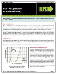
WHITE PAPER: WP011<br />
Selecting eGaN® FET Optimal On-Resistance<br />
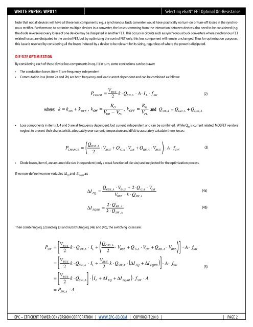
Note that not all devices will have all these loss components, e.g. a synchronous buck converter would have practically no turn-on or turn-off losses in the synchronous<br />
rectifier. Furthermore, to optimize multiple devices in a converter, the losses stemming from the interaction between devices also need to be considered (e.g.<br />
the diode reverse recovery losses of one device may be dissipated in another FET. This occurs in circuits such as synchronous buck converters where synchronous FET<br />
related losses are dissipated in the control FET, but by optimizing the control FET only, this loss component will remain unchanged. Thus for optimization purposes,<br />
this issue is resolved by considering all the losses induced by a device to be relevant for its sizing, regardless of where the power is dissipated.<br />
Die Size Optimization<br />
By considering each of these device loss components in eq. (1) in turn, some conclusions can be drawn:<br />
• The conduction losses (item 1) are frequency independent<br />
• Commutation loss (items 2a and 2b) are both frequency and load current dependent and can be combined as follows:<br />
where:<br />
k k ON<br />
+ k OFF<br />
P<br />
k<br />
= ON<br />
V<br />
2<br />
RG<br />
=<br />
V − V<br />
BUS<br />
COMM<br />
= k ⋅QSW , A<br />
DR<br />
PL<br />
⋅ A⋅<br />
I<br />
R<br />
L<br />
⋅ f<br />
SW<br />
G<br />
k<br />
OFF<br />
= and Q<br />
SW, A<br />
= QGD,<br />
A<br />
+ QGS2, A<br />
VPL<br />
(2)<br />
• Loss components in items 3, 4 and 5 are all frequency dependent, but current independent and can be combined. While Q RR<br />
is current related, MOSFET vendors<br />
neglect to present their characteristic adequately over current, temperature and di/dt to accurately calculate these losses:<br />
(<br />
Q<br />
)<br />
2<br />
OSS,<br />
A<br />
P<br />
CHARGE<br />
= ⋅ VBUS<br />
+ Q<br />
G,A<br />
⋅ VDR<br />
+ QRR<br />
A<br />
⋅ VBUS<br />
⋅ A⋅<br />
f<br />
,<br />
SW<br />
(3)<br />
• Diode losses, item 6, are assumed die size independent (only a weak function of die size) and neglected for the optimization process.<br />
If we now define two new variables ΔI EQ<br />
and ΔI EQRR<br />
as:<br />
∆I<br />
EQ<br />
Q<br />
=<br />
OSS , A<br />
⋅ VBUS<br />
+ 2<br />
V<br />
BUS<br />
⋅ Q<br />
⋅ k ⋅ Q<br />
G,A<br />
SW,<br />
A<br />
⋅ V<br />
DR<br />
(4a)<br />
∆I<br />
EQRR<br />
=<br />
2 ⋅ Q<br />
k ⋅ Q<br />
RR,<br />
A<br />
SW , A<br />
(4b)<br />
Then combining eq. (2) and eq. (3) and substituting eq. (4a) and (4b), the <strong>switching</strong> losses are:<br />
P<br />
SW<br />
=<br />
=<br />
=<br />
[<br />
V<br />
(<br />
Q<br />
k ⋅ Q ⋅ I +<br />
2<br />
2<br />
⋅ V + Q ⋅ V + Q<br />
)]<br />
⋅ V<br />
[<br />
V<br />
V<br />
k ⋅ Q ⋅ I +<br />
2<br />
2<br />
k ⋅ Q ⋅ ( ∆I<br />
+ ∆I<br />
)]<br />
⋅ A⋅<br />
f<br />
[<br />
V<br />
2<br />
k ⋅ Q<br />
]<br />
⋅ ( I + ∆I<br />
+ ∆I<br />
) ⋅ f ⋅ A<br />
= P<br />
BUS<br />
BUS<br />
BUS<br />
SW,<br />
A<br />
⋅ A<br />
SW,<br />
A<br />
SW,<br />
A<br />
SW , A<br />
L<br />
L<br />
L<br />
OSS,<br />
A<br />
BUS<br />
EQ<br />
BUS<br />
SW,<br />
A<br />
EQRR<br />
G,A<br />
EQ<br />
SW<br />
DR<br />
EQRR<br />
RR,<br />
A<br />
BUS<br />
SW<br />
⋅ A ⋅<br />
f<br />
SW<br />
(5)<br />
EPC – EFFICIENT POWER CONVERSION CORPORATION | WWW.EPC-CO.COM | COPYRIGHT 2013 | | PAGE 2