application switching
Selecting eGaN® FET Optimal On-Resistance - EPC
Selecting eGaN® FET Optimal On-Resistance - EPC
- No tags were found...

You also want an ePaper? Increase the reach of your titles
YUMPU automatically turns print PDFs into web optimized ePapers that Google loves.
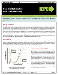
WHITE PAPER: WP011<br />
Selecting eGaN® FET Optimal On-Resistance<br />
Appendix<br />
R DS(ON),A On state resistance at 100 °C normalized for a die area taken as 1 Ω. All other device parameters are normalized with respect to this.<br />
R G<br />
V BUS<br />
I L<br />
D<br />
f SW<br />
V PL<br />
V DR<br />
Q GD,A<br />
Q GS2,A<br />
Q G,A<br />
Q SW,A<br />
Q OSS,A<br />
Q RR,A<br />
Resistance of gate drive path – either pull-up or pull-down as needed. This includes a 2 Ω pull-up and a 0.5 Ω pull down driver resistance (that is die size<br />
independent) and 0.6 Ω internal eGaN FET gate resistance. This number tends to be die size independent as smaller die have both shorter and narrower<br />
effective gate traces. For MOSFETs, the datasheet value is used and also assumed die size independent.<br />
The DC bus voltage that the <strong>switching</strong> node sees during operation. e.g. Input voltage for a Buck and output voltage for a Boost.<br />
This is the average inductor current and/or switch current during the switch on-state. Ripple is neglected such that the same value can be used throughout.<br />
Device on-time duty cycle is the fraction of the total cycle for with the device being optimized is conducting.<br />
This refers to the frequency at which the eGaN FET or MOSFET is <strong>switching</strong>.<br />
The plateau voltage of a device at rated current. Although this value may vary significantly with load, it is assumed constant during optimization for simplicity.<br />
Gate drive voltage<br />
Miller charge per normalized die area. This is assumed constant for a given bus voltage and calculated from the datasheet values and related charge graph.<br />
Gate charge between device threshold and plateau voltage per normalized die area. This is constant for a given load current and calculated from the datasheet<br />
value at rated current.<br />
Total normalized gate charge at given device drive voltage calculated from datasheet.<br />
Total normalized <strong>switching</strong> charge from reaching threshold to end of plateau.<br />
Total normalized device output charge a given bus voltage and calculated from the datasheet values and related charge graph.<br />
Total normalized device diode reverse recovery charge taken from the MOSFET datasheets.<br />
V F<br />
Forward drop of the device diode carrying a current I L<br />
.<br />
Δt<br />
k ON<br />
k OFF<br />
Total diode conduction interval per <strong>switching</strong> cycle.<br />
The inverse of the gate current during device turn-on ; assumed constant for optimization.<br />
The inverse of the gate current during device turn-off; assumed constant for optimization.<br />
Assumptions and approximations<br />
• Common source inductance (CSI) related increase in <strong>switching</strong> loss is discussed separately, but neglected for optimization purposes.<br />
• Temperature dependence of on-resistance is considered. All values are optimized based on ‘typical’ datasheet values at 100 °C. To determine the equivalent 25 °C<br />
values, the final optimized on-resistance value has to be normalized back to 25 °C.<br />
• Q OSS<br />
losses assume one <strong>switching</strong> edge is ZVS and one is ‘hard’ <strong>switching</strong>, i.e. the Q OSS<br />
energy is lost at device turn-on or turn-off only.<br />
• Q GS2<br />
varies with current at turn-on/off, but the value used is taken from the data sheet at rated current – thus will overestimate this component for lighter loads. It<br />
has a smaller impact at higher voltages as shown below. Also the gate drive current for this interval is calculated using the same plateau voltage, thereby overestimating<br />
turn-on time and under estimating turn-off.<br />
40 V 40 V 100 V 200 V<br />
V BUS 12 V 24 V 48 V 100 V<br />
Q GS2,A<br />
Q<br />
GD , A<br />
@ rated I DS 3.5 pC / Ω 3.5 pC / Ω 5 pC / Ω 9 pC / Ω<br />
@ V BUS 6 pC / Ω 7 pC / Ω 14 pC / Ω 35 pC / Ω<br />
Q GD /(Q SW ) 6/9.5 =0.63 7/10.5 =0.67 14/19 = 0.73 35/42 = 0.83<br />
Error of Q SW with varying load current 0 to 37% 0 to 33% 0 to 27% 0 to 17%<br />
EPC – EFFICIENT POWER CONVERSION CORPORATION | WWW.EPC-CO.COM | COPYRIGHT 2013 | | PAGE 8