
You also want an ePaper? Increase the reach of your titles
YUMPU automatically turns print PDFs into web optimized ePapers that Google loves.
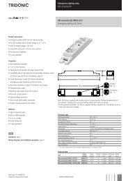
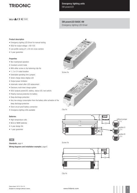
Emergency lighting units<br />
<strong>EM</strong> <strong>powerLED</strong><br />
<strong>EM</strong> <strong>powerLED</strong> <strong>BASIC</strong> 4W<br />
Emergency lighting LED Driver<br />
Product description<br />
• Emergency lighting LED Driver for manual testing<br />
• SELV for output voltage < 60 V DC<br />
• Low profile casing (21 x 30 mm cross-section)<br />
• 5-year guarantee<br />
Properties<br />
• Non maintained operation<br />
• Constant current mode<br />
• With either screw or clip fastening (clip-fix)<br />
• 1, 2 or 3 h rated duration<br />
• Selectable operating time (jumper)<br />
• Green charge status display LED<br />
• Output power limitation<br />
• Automatic restart after LED replacement<br />
• Electronic multi-level charge system<br />
• SELV (outputs <strong>powerLED</strong>, battery, status LED, test switch)<br />
• Polarity reversal protection for battery<br />
• Deep discharge protection<br />
• Very low energy consumption from the battery after activation of the<br />
deep discharge protection<br />
• Short-circuit-proof battery connection<br />
• Emergency lighting LEDs available<br />
Screw-fix<br />
Clip-fix<br />
Batteries<br />
• High-temperature cells<br />
• NiCd or NiMH batteries<br />
• 4-year design life<br />
• 1-year guarantee<br />
without jumper<br />
position A<br />
position B<br />
È<br />
Standards, page 4<br />
Wiring diagrams and installation examples, page 6<br />
Screw-fix<br />
Clip-fix<br />
Data sheet 10/15-724-15<br />
Subject to change without notice.<br />
www.tridonic.com 1
Emergency lighting units<br />
<strong>EM</strong> <strong>powerLED</strong><br />
Technical data<br />
Rated supply voltage<br />
220 – 240 V<br />
Mains frequency<br />
50 / 60 Hz<br />
Typ. λ (at 230 V, 50 Hz) 0.34<br />
Forward voltage range LED module (1 x LED)<br />
2.8 – 3.4 V<br />
Forward voltage range LED module (2 x LED)<br />
5.6 – 6.8 V<br />
LED current in emergency operation (1 x LED) 1.000 mA<br />
LED current in emergency operation (2 x LED) 700 mA<br />
Typ. output power (1 x LED)<br />
3.4 W<br />
Typ. output power (2 x LED)<br />
4.5 W<br />
Time to light<br />
0.23 s from detection of emergency event<br />
Overvoltage protection 320 V (for 1 h)<br />
Battery discharge current See page 4<br />
Max. casing temperature tc 70 °C<br />
Ambient temperature ta -25 ... +45 °C<br />
Mains voltage changeover threshold according to EN 60598-2-22<br />
Type of protection<br />
IP20<br />
Ordering data<br />
Type<br />
Article number Packaging,<br />
carton<br />
Packaging,<br />
pallet<br />
Weight<br />
per pc.<br />
Max. number<br />
of LED<br />
Power<br />
Screw fastening version<br />
<strong>EM</strong> <strong>powerLED</strong> 4 W <strong>BASIC</strong> 89800122 25 pc(s). 600 pc(s). 0.101 kg 2 4 W<br />
<strong>EM</strong> <strong>powerLED</strong> 4W <strong>BASIC</strong> NiMH 89800444 25 pc(s). 600 pc(s). 0.101 kg 2 4 W<br />
Clip fastening version<br />
<strong>EM</strong> <strong>powerLED</strong> 4 W <strong>BASIC</strong> 89800121 25 pc(s). 600 pc(s). 0.101 kg 2 4 W<br />
Specific technical data<br />
Type<br />
Mains current in charging operation<br />
Mains power in charging operation<br />
Rated duration<br />
Initial charge Fast recharge Trickle charge 1 Initial charge Fast recharge Trickle charge 1<br />
<strong>EM</strong> <strong>powerLED</strong> 4 W <strong>BASIC</strong> 1 h 21.0 mA 27.5 mA 15.2 mA 2.0 W 3.0 W 1.2 W<br />
<strong>EM</strong> <strong>powerLED</strong> 4 W <strong>BASIC</strong> 2 h 27.5 mA 32.4 mA 21.0 mA 3.0 W 3.7 W 2.0 W<br />
<strong>EM</strong> <strong>powerLED</strong> 4 W <strong>BASIC</strong> 3 h 27.5 mA 32.4 mA 21.0 mA 3.0 W 3.7 W 2.0 W<br />
<strong>EM</strong> <strong>powerLED</strong> 4 W <strong>BASIC</strong> NiMH 1 h 19.0 mA 24.0 mA 13.0 mA 1.7 W 2.4 W 1.0 W<br />
<strong>EM</strong> <strong>powerLED</strong> 4 W <strong>BASIC</strong> NiMH 2 h 30.0 mA 32.0 mA 13.0 mA 3.1 W 3.3 W 1.1 W<br />
<strong>EM</strong> <strong>powerLED</strong> 4 W <strong>BASIC</strong> NiMH 3 h 30.0 mA 32.0 mA 13.0 mA 3.1 W 3.3 W 1.1 W<br />
1<br />
For <strong>EM</strong> <strong>powerLED</strong> 4 W <strong>BASIC</strong> NiMH: average over 20 min. (4 min. charge / 16 min. off)<br />
Data sheet 10/15-724-15<br />
Subject to change without notice.<br />
www.tridonic.com 2
Emergency lighting units<br />
<strong>EM</strong> <strong>powerLED</strong><br />
ACCES-<br />
SORIES<br />
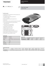
Test switch <strong>EM</strong>2<br />
Product description<br />
• For connection to the emergency lighting unit<br />
• For checking the device function<br />
Ordering data<br />
Type<br />
Article number<br />
Packaging,<br />
bag<br />
Packaging,<br />
carton<br />
Weight<br />
per pc.<br />
Test switch <strong>EM</strong> 2 89805277 25 pc(s). 200 pc(s). 0.011 kg<br />
ACCES-<br />
SORIES<br />
Status indication green LED<br />
Product description<br />
• A green LED indicates that charging current is flowing into the<br />
battery<br />
Ordering data<br />
Type<br />
Article number<br />
Packaging,<br />
bag<br />
Packaging,<br />
carton<br />
Weight<br />
per pc.<br />
LED <strong>EM</strong> green 89899605 25 pc(s). 200 pc(s). 0.011 kg<br />
LED <strong>EM</strong> green, ultra high brightness 89899756 25 pc(s). 800 pc(s). 0.012 kg<br />
Data sheet 10/15-724-15<br />
Subject to change without notice.<br />
www.tridonic.com 3
Emergency lighting units<br />
<strong>EM</strong> <strong>powerLED</strong><br />
Battery selection<br />
<strong>EM</strong> <strong>powerLED</strong> 4W <strong>BASIC</strong>, 1 / 2 / 3 h<br />
Type<br />
<strong>EM</strong> <strong>powerLED</strong> 4W <strong>BASIC</strong><br />
<strong>EM</strong> <strong>powerLED</strong> 4W<br />
<strong>BASIC</strong> NiMH<br />
Technology<br />
and capacity<br />
Design<br />
Number<br />
of cells<br />
Type<br />
Article no. 89800121 / 89800122 89800444<br />
Cells 5 cells 5 cells<br />
Duration 1 h 2 / 3 h 1 h 2 / 3 h<br />
Article no.<br />
NiCd 4 Ah stick 1 x 5 Accu-NiCd 5A 89895973 •<br />
D cells 1 stick + stick 3 + 2 Accu-NiCd 5C 55 89800090 •<br />
NiMH 2 Ah<br />
Cs cells<br />
Assignable batteries<br />
stick 1 x 5 Accu-NiMH C 5A 89899703 • •<br />
side by side 5 x 1 Accu-NiMH C 5B 89899704 • •<br />
NiMH 4 Ah<br />
LA cells<br />
stick + stick 2 + 3 Accu-NiMH 4Ah 5C CON 89800439 •<br />
1<br />
50°C batteries also available (see seperate datasheet at www.tridonic.com)<br />
Battery charge / discharge data<br />
<strong>EM</strong> <strong>powerLED</strong> 4W <strong>BASIC</strong>, 1 / 2 / 3 h<br />
Type<br />
<strong>EM</strong> <strong>powerLED</strong> 4W <strong>BASIC</strong><br />
<strong>EM</strong> <strong>powerLED</strong> 4W<br />
<strong>BASIC</strong> NiMH<br />
Article no. 89800121 / 89800122 89800444<br />
Cells 5 cells 5 cells<br />
Duration 1 h 2 / 3 h 1 h 2 / 3 h<br />
Battery charge<br />
time<br />
Initial charge<br />
20 h<br />
Fast recharge 10 h 15 h 10 h 15 h<br />
Trickle charge<br />
continuously<br />
Charge current<br />
Initial charge 130 mA 250 mA 130 mA 300 mA<br />
Fast recharge 250 mA 330 mA 210 mA 330 mA<br />
Trickle charge 60 mA 130 mA<br />
127 mA / 4 min.<br />
0 mA / 16 min.<br />
201 mA / 4 min.<br />
0 mA / 16 min.<br />
Discharge current 1,100 mA 1,100 mA 1,100 mA 1,100 mA<br />
Data sheet 10/15-724-15<br />
Subject to change without notice.<br />
www.tridonic.com 4
Emergency lighting units<br />
<strong>EM</strong> <strong>powerLED</strong><br />
Standards<br />
• according to EN 50172<br />
• according to EN 60598-2-22<br />
• EN 61347-2-7<br />
• EN 61347-2-13<br />
• EN 62384<br />
• EN 55015<br />
• EN 61000-2-3<br />
• EN 61000-3-3<br />
• EN 61547<br />
• EN 60068-2-64<br />
• EN 60068-2-29<br />
• EN 60068-2-30<br />
Storage, installation and commissioning<br />
Relevant information about storage conditions, installation and commissioning are<br />
provided in the battery datasheets.<br />
Batteries<br />
Connection method: 4.8 x 0.5 mm spade tag welded to end of cell<br />
For stick packs this connection is accessible after the battery caps have been<br />
fitted.<br />
To inhibit inverter operation disconnect the batteries by removing the connector<br />
from the battery spade tag.<br />
For battery data see separate data sheet.<br />
Technical data batteries<br />
Accu-NiCd<br />
Case temperature range<br />
to ensure 4 years design life<br />
4.2 / 4.5 Ah D +5 °C to +55 °C<br />
Battery voltage/cell<br />
1.2 V<br />
Single cell dimensions<br />
4.2/ 4.5 Ah D<br />
Diameter<br />
32.5 mm<br />
Height<br />
60.5 mm<br />
Capacity D<br />
4.2 / 4.5 Ah<br />
Max. short term temperature (reduced life-time) 70 °C<br />
Max. number discharge cycles<br />
Packing quantity<br />
4 cycles per year plus<br />
4 cycles during<br />
comissioning<br />
5 pcs. per carton<br />
Accu-NiMH<br />
Case temperature range<br />
to ensure 4 years design life<br />
2.0 Ah Cs +5 °C to +55 °C<br />
4.0 Ah LA +5 °C to +50 °C<br />
Battery voltage<br />
1.2 V<br />
Single cell dimensions<br />
2.0 Ah Cs<br />
Diameter<br />
22 mm<br />
Height<br />
42.5 mm<br />
4.0 Ah LA<br />
Diameter<br />
18.3 mm<br />
Height<br />
90 mm<br />
Capacity Cs / LA<br />
2.0 Ah / 4.0 Ah<br />
Max. short term temperature (reduced life-time) 70 °C<br />
Max. number discharge cycles 2.0 Ah Cs<br />
Max. number discharge cycles 4.0 Ah LA<br />
Packing quantity<br />
4 cycles per year plus<br />
4 cycles during<br />
comissioning<br />
2 cycles per year plus<br />
4 cycles during<br />
comissioning<br />
5 pcs. per carton<br />
Duration link selection<br />
Duration<br />
1 hr<br />
2 hr<br />
3 hr<br />
Link Position<br />
without jumper<br />
position A<br />
position B<br />
Jumper selection<br />
Module supplied with jumper in 3 hours position (position B).<br />
The position of the link will only be read on first power up. If it is changed afterwards<br />
both the battery and mains supply must be disconnected for<br />
10 seconds to enable the <strong>EM</strong> <strong>powerLED</strong> to read the new link position on reconnection<br />
of the battery and mains. It will lead to a false battery failure indication if<br />
the link is changed after installation without this reset.<br />
Further technical data<br />
The <strong>EM</strong> <strong>powerLED</strong> has a unique power regulation circuit; this is designed to limit<br />
the total power drawn from the battery in the event of using LED’s with a forward<br />
voltage (Vf) higher than 3.4 V.<br />
In such cases the unit will reduce the LED current in order to maintain an<br />
acceptable drain current from the battery and hence meet the required duration<br />
time. This feature enables the <strong>EM</strong> <strong>powerLED</strong> to have minimum battery count for<br />
a given range of LED’s.<br />
Life-time<br />
Average life-time 50,000 hours under rated conditions with a failure rate<br />
of less than 10 %. Average failure rate of 0.2 % per 1000 operating hours.<br />
Data sheet 10/15-724-15<br />
Subject to change without notice.<br />
www.tridonic.com 5
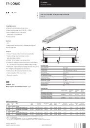
Emergency lighting units<br />
<strong>EM</strong> <strong>powerLED</strong><br />
Mechanical details<br />
Case manufactured from polycarbonate.<br />
Glow-wire test according to EN 61347-1 with increased temperature of 850 °C<br />
passed.<br />
LED status indicator<br />
• Green<br />
• Mounting hole 6.5 mm dia<br />
• Lead length 1000 mm<br />
Test switch<br />
• Mounting hole 7.0 mm dia<br />
• Lead length 550 mm<br />
Battery leads<br />
• Quantity: 1 red and 1 black<br />
• Length: 1 m<br />
• Wire type: 0.5 mm 2 solid conductor<br />
• Insulation rating: 90 °C<br />
Battery end termination<br />
Push on 4.8 mm receptacle to suit battery spade fitted with insulating cover<br />
Module end termination<br />
8.0 mm stripped insulation<br />
Two-piece batteries are supplied with a 200 mm lead with 4.8 mm receptacles at<br />
each end and insulating covers to connect the separate sticks together.<br />
Wiring type and cross section<br />
Wiring<br />
mains (SL, N, L)<br />
LED (LED +, LED –)<br />
Wiring<br />
batteries (Bat +, Bat –)<br />
test switch (switch)<br />
status indication LED (status K, A)<br />
Use one wire for each terminal connector only.<br />
Max. lead insulation diameter<br />
Battery<br />
2.1 mm<br />
Test switch<br />
2.1 mm<br />
Indicator LED<br />
2.1 mm<br />
Maximum lead length<br />
LED<br />
status indication LED<br />
batteries<br />
3 m<br />
1 m<br />
1 m<br />
0.5 – 1.5 mm² solid or fine-stranded<br />
0.5 – 1.0 mm² fine-stranded with ferrule<br />
8.5 – 9.5 mm<br />
0.2 – 0.5 mm² solid or fine-stranded<br />
0.25 mm² fine-stranded with ferrule<br />
8.5 – 9.5 mm<br />
Recommended fixing details for clip fixing<br />
125,2<br />
0,4 mm to 0,6 mm thick gear tray<br />
fixing slots<br />
4,3 x 9,3 mm<br />
Release of the wiring<br />
Press down the “push button” and remove<br />
the cable from front.<br />
122,4<br />
0,6 mm to 1,1 mm thick gear tray<br />
Isolation and electric strength testing of luminaires<br />
Electronic LED Drivers can be damaged by high voltage. This has to be considered<br />
during the routine testing of the luminaires in production.<br />
According to IEC 60598-1 Annex Q (informative only!) or ENEC 303-Annex A, each<br />
luminaire should be submitted to an isolation test with 500 VDC for 1 second. This<br />
test voltage should be connected between the interconnected phase and neutral<br />
terminals and the earth terminal. The isolation resistance must be at least 2 MΩ.<br />
As an alternative, IEC 60598-1 Annex Q describes a test of the electrical strength<br />
with 1,500 VAC (or 1,414 x 1,500 VDC). To avoid damage to the electronic LED<br />
Drivers this test must not be conducted.<br />
Maximum loading of automatic circuit breakers<br />
Automatic circuit breaker type B10 B13 B16 B20 Inrush current<br />
Installation Ø 1.5 mm 2 1.5 mm 2 2.5 mm 2 2.5 mm 2 I max<br />
Time<br />
<strong>EM</strong> <strong>powerLED</strong> 4 W <strong>BASIC</strong> 90 130 130 130 10 A 120 μs<br />
<strong>EM</strong> <strong>powerLED</strong> 4 W <strong>BASIC</strong> NiMH 90 130 130 130 10 A 120 μs<br />
Data sheet 10/15-724-15<br />
Subject to change without notice.<br />
www.tridonic.com 6
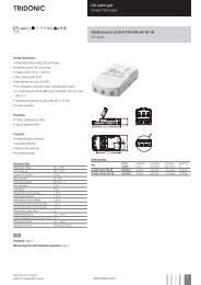
Emergency lighting units<br />
<strong>EM</strong> <strong>powerLED</strong><br />
Wiring diagrams<br />
Wiring diagram for one LED or two LED in series<br />
Neutral<br />
Permanent line<br />
N<br />
L<br />
<strong>EM</strong> <strong>powerLED</strong> <strong>BASIC</strong><br />
status K<br />
status A<br />
switch<br />
switch<br />
LED +<br />
LED –<br />
Bat –<br />
Bat +<br />
pink<br />
orange<br />
LED<br />
Optional<br />
Test Switch<br />
+ – + –<br />
LED<br />
Battery<br />
Wiring diagram for multiple LED (3–12) in parallel<br />
Neutral<br />
Permanent line<br />
N<br />
L<br />
<strong>EM</strong> <strong>powerLED</strong> <strong>BASIC</strong><br />
status K<br />
status A<br />
switch<br />
switch<br />
LED +<br />
LED –<br />
Bat –<br />
Bat +<br />
pink<br />
orange<br />
LED<br />
Optional<br />
Test Switch<br />
LED<br />
+ – + – + – + –<br />
Battery<br />
Take care that the LED is connected with the right polarity. LED that are connected<br />
to the <strong>EM</strong> <strong>powerLED</strong> devices should have a reverse polartity protection<br />
device such as a schottky diodes fitted, otherwise irreversible damage could<br />
occur if the LED is connected in reverse polarity. Any protection device must be<br />
capaple of handling in excess of 1,000 mA.<br />
Note: Please ensure that at the terminal of the <strong>EM</strong> <strong>powerLED</strong> module the battery<br />
negative is not connected to the negative of the LED load.<br />
Wiring diagram with LED Driver<br />
Manually tested emergency lighting with combined LED modules for<br />
general and emergency lighting (e.g. STARK QLE CLASSIC <strong>EM</strong>,<br />
STARK LLE 24-280-1250 <strong>EM</strong>, STARK CLE CLASSIC <strong>EM</strong>,<br />
STARK SLE CLASSIC <strong>EM</strong>):<br />
Due to the fact that independent circuits are used for general and emergency<br />
lighting it is important that the normal supply of the mains LED Driver is switched<br />
off together with the permanent emergency supply prior to checking<br />
the operation of the emergency LEDs.<br />
If this is not done then it may not be possible to see that the emergency LEDs<br />
are operating.<br />
Use a circuit similar to that shown next.<br />
220–240 V<br />
50/60 Hz<br />
L<br />
N<br />
PE<br />
Test Switch*<br />
Light Switch<br />
N<br />
L<br />
PE<br />
N<br />
L<br />
<strong>EM</strong> <strong>powerLED</strong> <strong>BASIC</strong><br />
LED<br />
mains control gear<br />
status K<br />
status A<br />
switch<br />
switch<br />
LED +<br />
LED –<br />
Bat –<br />
Bat +<br />
LED +<br />
LED –<br />
pink<br />
orange<br />
LED<br />
Optional<br />
Test Switch<br />
Battery<br />
+ <strong>EM</strong><br />
- <strong>EM</strong><br />
+<br />
-<br />
LED Module<br />
* Use 230 V Test switch<br />
Data sheet 10/15-724-15<br />
Subject to change without notice.<br />
www.tridonic.com 7
Emergency lighting units<br />
<strong>EM</strong> <strong>powerLED</strong><br />
Wiring instructions<br />
• The <strong>powerLED</strong> terminals, battery, indicator LED and test switch terminals are<br />
classified as SELV. Keep the wiring of the input terminals separated from the<br />
wiring of the SELV terminals or consider special wiring (double insulation,<br />
6 mm creepage and clearance) when these connections should be kept SELV.<br />
• The output to the LED is DC but has high frequency content at 125 kHz, which<br />
should be considered for good <strong>EM</strong>C compliance.<br />
• <strong>powerLED</strong> leads should be separated from the mains connections and wiring<br />
for good <strong>EM</strong>C performance. With some luminaires it may be necessary to add<br />
a ferrite bead inductor to obtain satisfactory <strong>EM</strong>C performance.<br />
• Maximum lead length on the <strong>powerLED</strong> terminals is 3 m. For a good<br />
<strong>EM</strong>C performance keep the LED wiring as short as possible.<br />
• Maximum lead length for the Test switch and Indicator LED connection is 1 m.<br />
The test switch and Indicator LED wiring should be separated from the <strong>powerLED</strong><br />
leads to prevent noise coupling.<br />
• Battery leads are specified with 0.5 mm 2 cross section and a length<br />
of < 1.3 m<br />
Additional information<br />
Additional technical information at<br />
www.tridonic.com → Technical Data<br />
Guarantee conditions at<br />
www.tridonic.com → Services<br />
No warranty if device was opened.<br />
Data sheet 10/15-724-15<br />
Subject to change without notice.<br />
www.tridonic.com 8