LED control gear Compact dimming Uconverter LCAI 15 W 350 mA one4all ECO series
TALEXXconverter LCAI 15 W one4all - Tridonic
TALEXXconverter LCAI 15 W one4all - Tridonic

Create successful ePaper yourself
Turn your PDF publications into a flip-book with our unique Google optimized e-Paper software.
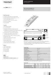
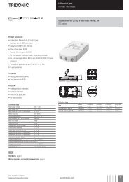
<strong>LED</strong> <strong>control</strong> <strong>gear</strong><br />
<strong>Compact</strong> <strong>dimming</strong><br />
<strong>Uconverter</strong> <strong>LCAI</strong> <strong>15</strong> W <strong>350</strong> <strong>mA</strong> <strong>one4all</strong><br />
<strong>ECO</strong> <strong>series</strong><br />
Product description<br />
• 1 addressable output channel<br />
• <strong>350</strong> <strong>mA</strong> PWM output signal<br />
• Short-circuit protection with automatic restart<br />
• No-load detection with automatic restart<br />
• Intelligent Temperature Guard (protection against thermal damage)<br />
• Connecting cable, cable cross-section 0.5 – 2.5 mm²<br />
• Power input on standby < 1 W<br />
• Output power <strong>15</strong> W<br />
• Overload protection with automatic restart<br />
• Strain relief<br />
Properties<br />
• switchDIM-MEMORY and corridorFUNCTION<br />
• Dimming range 1 to 100 %<br />
• Dimming curve adapted to the sensitivity of the eye<br />
• Noise-free precise <strong>control</strong> via DALI or DSI signal, switchDIM or<br />
corridorFUNCTION<br />
• Powerless switching via a digital interface (no need for switching via<br />
mains)<br />
• Fault reporting and programmable operating parameters in DALI<br />
mode<br />
• SELV<br />
Data sheet 08/<strong>15</strong>-914-<strong>15</strong><br />
Subject to change without notice.<br />
www.tridonic.com 1
<strong>LED</strong> <strong>control</strong> <strong>gear</strong><br />
<strong>Compact</strong> <strong>dimming</strong><br />
<strong>Uconverter</strong> <strong>LCAI</strong> <strong>15</strong> W <strong>350</strong> <strong>mA</strong> <strong>one4all</strong><br />
<strong>ECO</strong> <strong>series</strong><br />
Technical data<br />
Rated supply voltage<br />
Input voltage, AC<br />
Input voltage, DC 1<br />
Mains frequency<br />
Rated current (at 230 V 50 Hz)<br />
220 – 240 V<br />
198 – 264 V<br />
170 – 240 V<br />
0 / 50 / 60 Hz<br />
0.08 A<br />
Typ. current (220 V, 0 Hz, full load, <strong>15</strong> % <strong>dimming</strong> level) 14 <strong>mA</strong><br />
Efficiency > 84 %<br />
λ at 230 V / 50 Hz 0.6<br />
Max. input power<br />
Control input <strong>dimming</strong><br />
19 W<br />
DSI, DALI, switchDIM<br />
Dimming range 1 – 100 %<br />
PWM frequency<br />
Stand-by power at 230 V<br />
Output current<br />
400 Hz<br />
0.77 W<br />
<strong>350</strong> <strong>mA</strong><br />
Output current tolerance ± 7.5 %<br />
Output current ripple ± 17 %<br />
Max. repetitive output peak current ≤ output current + 25 %<br />
Max. non-repetitive output peak current ≤ output current + 25 %<br />
Output voltage range<br />
Max. output voltage 2<br />
Output power<br />
Output power range (without <strong>dimming</strong> opartion)<br />
Set up time at 230 V (acc. to the DALI standard)<br />
Time to light (at 230 V, 50 Hz, full load, acc. to DALI)<br />
Time to light (DC mode )<br />
Switchover time (AC/DC)<br />
Turn off time at full load<br />
Turn off time at 3 V<br />
Burst / surge peaks output side against PE<br />
9 – 45 V<br />
60 V<br />
<strong>15</strong> W<br />
3 – <strong>15</strong> W<br />
< 600 ms<br />
< 0.8 s<br />
< 0.5 s<br />
< 0.5 s<br />
30 ms<br />
< 300 ms<br />
4 kV<br />
ta operating (at life-time 50,000 h) -25 ... +50 °C<br />
Max. casing temperature tc 80 °C<br />
Storage temperature -25 ... +60 °C<br />
Dimensions LxWxH<br />
Hole spacing D<br />
1 On DC operation dimmlevel is always set to <strong>15</strong> % default.<br />
This can be adjusted to any level in masterCONFIGURATOR.<br />
2 In non-load operation.<br />
167 x 42 x 31 mm<br />
143 – 148 mm<br />
Ordering data<br />
Type<br />
Article number<br />
Packaging<br />
carton<br />
Packaging<br />
pallet<br />
Weight per pc.<br />
<strong>LCAI</strong> 0<strong>15</strong>/0<strong>350</strong> A020 <strong>one4all</strong> 28000735 20 pc(s). 800 pc(s). 0.121 kg<br />
Data sheet 08/<strong>15</strong>-914-<strong>15</strong><br />
Subject to change without notice.<br />
www.tridonic.com 2
<strong>LED</strong> <strong>control</strong> <strong>gear</strong><br />
<strong>Compact</strong> <strong>dimming</strong><br />
Standards<br />
EN 50172<br />
EN 550<strong>15</strong><br />
EN 61000-3-2<br />
EN 61000-3-3<br />
EN 61347-1<br />
EN 61347-2-13<br />
EN 6<strong>15</strong>47<br />
EN 62384<br />
EN 62386-207<br />
Control input (DA/D1, DA/D2)<br />
Digital DALI/DSI signal or switchDIM can be wired<br />
on the same terminals (DA/D1 and DA/D2).<br />
Digital signal DALI/DSI<br />
The <strong>control</strong> input is non-polar and protected against<br />
accidental connection with a mains voltage up to<br />
264 V. The <strong>control</strong> signal is not SELV. Control cable<br />
has to be installed in accordance to the<br />
requirements of low voltage installations.<br />
Different functions depending on each module.<br />
Dimming<br />
Dimming range 1 % to 100 %<br />
Digital <strong>control</strong> with:<br />
• DSI signal: 8 bit Manchester Code<br />
Speed 1 % to 100 % in 1.4 s<br />
• DALI signal: 16 bit Manchester Code<br />
Speed 1 % to 100 % in 0.1 s<br />
Programmable parameter:<br />
Minimum <strong>dimming</strong> level<br />
Maximum <strong>dimming</strong> level<br />
Default minimum = 1 %<br />
Programmable range 1 % ≤ MIN ≤ 100 %<br />
Default maximum = 100 %<br />
Programmable range 100 % ≥ MAX ≥ 1 %<br />
Dimming curve is adapted to the eye sensitiveness.<br />
DC emergency operation<br />
The <strong>LED</strong> Driver is designed for operation on DC<br />
voltage and pulsed DC voltage.<br />
Light output level programmable from 1 – 100 %<br />
Programming by extended DSI or DALI signal<br />
(16 bit).<br />
Default value is <strong>15</strong> %<br />
In DC operation <strong>dimming</strong> mode can be activated.<br />
The voltage-dependent input current of Driver incl.<br />
<strong>LED</strong> module is depending on the used load.<br />
The voltage-dependent no-load current of Driver<br />
(without or defect <strong>LED</strong> module) is for:<br />
AC: 16 <strong>mA</strong><br />
DC: 5 <strong>mA</strong><br />
switchDIM<br />
Integrated switchDIM function allows a direct<br />
connection of a push to make switch for <strong>dimming</strong><br />
and switching.<br />
Brief push (< 0.6 s) switches <strong>LED</strong> <strong>control</strong> <strong>gear</strong> ON<br />
and OFF. The <strong>LED</strong> <strong>control</strong> <strong>gear</strong>s switch-ON at light<br />
level set at switch-OFF.<br />
When the push to make switch is held, <strong>LED</strong> modules<br />
are dimmed. After repush the <strong>LED</strong> modules are<br />
dimmed in the opposite direction.<br />
In installations with <strong>LED</strong> <strong>control</strong> <strong>gear</strong>s with different<br />
<strong>dimming</strong> levels or opposite <strong>dimming</strong> directions (e.g.<br />
after a system extension), all <strong>LED</strong> <strong>control</strong> <strong>gear</strong>s can<br />
be synchronized to 50 % <strong>dimming</strong> level by a 10 s<br />
push.<br />
Use of push to make switch with indicator lamp is<br />
not permitted.<br />
corridorFUNCTION<br />
The corridorFUNCTION can be programmed in two<br />
different ways.<br />
To program the corridorFUNCTION by means of software<br />
a DALI-USB interface is needed in combination<br />
with a DALI PS. The software can be the<br />
masterCONFIGURATOR.<br />
To activate the corridorFUNCTION without using software<br />
a voltage of 230 V simply has to be applied for<br />
five minutes at the switchDIM connection.<br />
The unit will then switch automatically to the<br />
corridorFUNCTION.<br />
Note:<br />
If the corridorFUNCTION is wrongly activated in a<br />
switchDIM system (for example a switch is used<br />
instead of pushbutton), there is the option of installing<br />
a pushbutton and deactivating the corridorFUNCTION<br />
mode by five short pushes of the button within three<br />
seconds.<br />
switchDIM and corridorFUNCTION are very simple<br />
tools for <strong>control</strong>ling ballasts with conventional<br />
momentary-action switches or motion sensors.<br />
To ensure correct operation a sinusoidal mains voltage<br />
with a frequency of 50 or 60 Hz is required at<br />
the <strong>control</strong> input.<br />
Special attention must be paid to achieving clear<br />
zero crossings. Serious mains faults may impair the<br />
operation of switchDIM and corridorFUNCTION.<br />
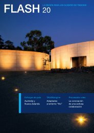
Dimming characteristics<br />
Digital <strong>dimming</strong> value<br />
255<br />
225<br />
200<br />
DALI<br />
175<br />
DSI<br />
<strong>15</strong>0<br />
125<br />
100<br />
75<br />
50<br />
25<br />
0<br />
0 10 20 30 40 50 60 70 80 90 100<br />
Relative lighting level %<br />
Dimming characteristics as seen by the human eye<br />
Wiring type and cross section<br />
The wiring can be in stranded wires with ferrules or<br />
solid. For perfect function of the screw terminals the<br />
strip length should be 6.5–7.5 mm for the input and<br />
output terminal.<br />
Double occupancy possible at max. 1.5 mm 2 cross<br />
section.<br />
Max. torque at the clamping screw: 0.5 Nm<br />
The maximum secondary cable length at the terminals<br />
is 2 m. The <strong>LED</strong> wiring should be kept as short<br />
as possible to ensure good EMC.<br />
Input / Output terminal<br />
wire preparation:<br />
0.5 – 2.5 mm²<br />
7.5 – 8.5 mm<br />
Thermal protection of the unit<br />
The unit also has an ITG (Intelligent Temperature<br />
Guard). This protects it from overheating. If the unit<br />
is operated at too high a temperature the output is<br />
reduced to as little as 70 %.<br />
Installation instructions<br />
Please note that <strong>LCAI</strong> 0<strong>15</strong>/0<strong>350</strong> A020 <strong>one4all</strong><br />
complies with protection class II so special<br />
measures are needed if it is to be installed in protection<br />
class I applications / luminaires.<br />
Please note the requirements set out in the<br />
document <strong>LED</strong>_Betriebsgeraete_installationshinweis.pdf<br />
(http://www.tridonic.com/com/de/technische-doku.asp).<br />
Data sheet 08/<strong>15</strong>-914-<strong>15</strong><br />
Subject to change without notice.<br />
www.tridonic.com 3
<strong>LED</strong> <strong>control</strong> <strong>gear</strong><br />
<strong>Compact</strong> <strong>dimming</strong><br />
Expected life-time<br />
Type ta 40 °C 50 °C<br />
<strong>LCAI</strong> 0<strong>15</strong>/0<strong>350</strong> A020<br />
tc 70 °C 80 °C<br />
Life-time >100,000 h 50,000 h<br />
The <strong>LED</strong> <strong>control</strong> <strong>gear</strong> is designed for a life-time stated above under reference conditions and with a failure probability of less than 10 %.<br />
Maximum loading of automatic circuit breakers<br />
Automatic circuit breaker type C10 C13 C16 C20 B10 B13 B16 B20<br />
Installation Ø 1.5 mm 2 1.5 mm 2 1.5 mm 2 2.5 mm 2 1.5 mm 2 1.5 mm 2 1.5 mm 2 2.5 mm 2<br />
<strong>LCAI</strong> 0<strong>15</strong>/0<strong>350</strong> A020 60 80 100 125 60 80 100 125<br />
Wiring diagrams<br />
220–240 V AC , 0/50/60 Hz<br />
L<br />
N<br />
DALI/DSI<br />
~<br />
~<br />
DC + –<br />
<strong>Uconverter</strong><br />
<strong>LCAI</strong> ... Ax20<br />
DALI/DSI<br />
+<br />
–<br />
+<br />
–<br />
Umodule<br />
220–240 V AC, 0/50/60 Hz<br />
L<br />
N<br />
switchDIM<br />
~<br />
~<br />
DC + –<br />
<strong>Uconverter</strong><br />
<strong>LCAI</strong> ... Ax20<br />
+<br />
–<br />
+<br />
–<br />
Umodule<br />
Isolation and electric strength testing of luminaires<br />
Electronic devices can be damaged by high voltage. This has to be considered<br />
during the routine testing of the luminaires in production.<br />
According to IEC 60598-1 Annex Q (informative only!) or ENEC 303-Annex A, each<br />
luminaire should be submitted to an isolation test with 500 V DC for 1 second. This<br />
test voltage should be connected between the interconnected phase and neutral<br />
terminals and the earth terminal.<br />
The isolation resistance must be at least 2 MΩ.<br />
As an alternative, IEC 60598-1 Annex Q describes a test of the electrical strength<br />
with <strong>15</strong>00 V AC (or 1.414 x <strong>15</strong>00 V DC). To avoid damage to the electronic devices this<br />
test must not be conducted.<br />
Additional information<br />
Additional technical information at<br />
www.tridonic.com → Technical Data<br />
Guarantee conditions at<br />
www.tridonic.com → Services<br />
No warranty if device was opened.<br />
Data sheet 08/<strong>15</strong>-914-<strong>15</strong><br />
Subject to change without notice.<br />
www.tridonic.com 4
<strong>LED</strong> <strong>control</strong> <strong>gear</strong><br />
<strong>Compact</strong> <strong>dimming</strong><br />
Diagrams <strong>LCAI</strong> 0<strong>15</strong>/0<strong>350</strong> A020<br />
Efficiency vs load<br />
Power factor vs load<br />
88<br />
0,7<br />
Efficiency [%]<br />
86<br />
84<br />
82<br />
80<br />
78<br />
76<br />
74<br />
72<br />
70<br />
45 50 55 60 65 70 75 80 85 90 95 100<br />
Load [%]<br />
Power factor<br />
0,6<br />
0,5<br />
0,4<br />
0,3<br />
0,2<br />
0,1<br />
0,0<br />
45 50 55 60 65 70 75 80 85 90 95 100<br />
Load [%]<br />
Data sheet 08/<strong>15</strong>-914-<strong>15</strong><br />
Subject to change without notice.<br />
www.tridonic.com 5