TALEXXconverter LCI 60 W 700/1050 mA TEC SR - Tridonic
TALEXXconverter LCI 60 W 700/1050 mA TEC SR - Tridonic
TALEXXconverter LCI 60 W 700/1050 mA TEC SR - Tridonic

Create successful ePaper yourself
Turn your PDF publications into a flip-book with our unique Google optimized e-Paper software.
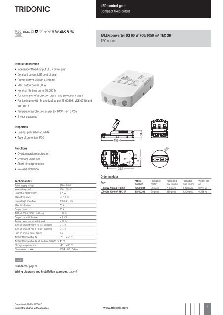
LED control gear<br />
Compact fixed output<br />
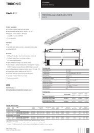
Uconverter <strong>LCI</strong> <strong>60</strong> W <strong>700</strong>/<strong>1050</strong> <strong>mA</strong> <strong>TEC</strong> <strong>SR</strong><br />
<strong>TEC</strong> series<br />
Product description<br />
• Independent fixed output LED control gear<br />
• Constant current LED control gear<br />
• Output current <strong>700</strong> or 1,050 <strong>mA</strong><br />
• Max. output power <strong>60</strong> W<br />
• Nominal life-time up to 50,000 h<br />
• For luminaires of protection class I and protection class II<br />
• For luminaires with M and MM as per EN <strong>60</strong>598, VDE 0710 and<br />
VDE 0711<br />
• Temperature protection as per EN 61347-2-13 C5e<br />
• 5-year guarantee<br />
Properties<br />
• Casing: polycarbonat, white<br />
• Type of protection IP20<br />
159,4<br />
34<br />
Functions<br />
• Overtemperature protection<br />
37<br />
Ø 86<br />
• Overload protection<br />
• Short-circuit protection<br />
tc<br />
31<br />
33<br />
82<br />
• No-load protection<br />
125,5<br />
Technical data<br />
Rated supply voltage<br />
220 – 240 V<br />
Input voltage, AC<br />
198 – 264 V<br />
Current at 50 Hz 230 V<br />
0.29 A<br />
Mains frequency<br />
50 / <strong>60</strong> Hz<br />
Overvoltage protection<br />
300 V AC, 1 h<br />
Max. input power<br />
70 W<br />
Output power<br />
<strong>60</strong> W<br />
THD (at 230 V, 50 Hz, full load) < 20 %<br />
Output current tolerance ± 7.5 %<br />
Typical ripple current at full load ± 25 %<br />
Turn on time (at 230 V, 50 Hz, full load) ≤ 0.7 s<br />
Turn off time (at 230 V, 50 Hz, full load) ≤ 0.7 s<br />
Hold on time at power failure<br />
0 s<br />
Ambient temperature ta -20 ... +50 °C<br />
Ambient temperature ta (at life-time 50,000 h) 40 °C<br />
Storage temperature ts -40 ... +80 °C<br />
Dimensions L x W x H<br />
159.4 x 82 x 34 mm<br />
Ordering data<br />
Type<br />
Article<br />
number<br />
Packaging,<br />
carton<br />
Packaging,<br />
low volume<br />
Packaging,<br />
high volume<br />
Weight per<br />
pc.<br />
<strong>LCI</strong> <strong>60</strong>W <strong>700</strong><strong>mA</strong> <strong>TEC</strong> <strong>SR</strong> 87500201 20 pc(s). 280 pc(s). 1,120 pc(s). 0.220 kg<br />
<strong>LCI</strong> <strong>60</strong>W <strong>1050</strong><strong>mA</strong> <strong>TEC</strong> <strong>SR</strong> 87500203 20 pc(s). 280 pc(s). 1,120 pc(s). 0.228 kg<br />
È<br />
Standards, page 3<br />
Wiring diagrams and installation examples, page 4<br />
Data sheet 01/15-LC036-7<br />
Subject to change without notice.<br />
www.tridonic.com 1
LED control gear<br />
Compact fixed output<br />
Specific technical data<br />
Type<br />
Output<br />
current<br />
Power<br />
factor at full<br />
load 1<br />
Efficiency<br />
at full<br />
load 1<br />
Power Efficiency<br />
factor at at min.<br />
min. load 1 load 1<br />
Min. output<br />
voltage 1<br />
Max. output<br />
voltage 1<br />
Max. output<br />
voltage (noload<br />
voltage)<br />
Max. repetitive<br />
output peak<br />
current at full<br />
load 12<br />
Max. repetitive<br />
output peak<br />
current at min.<br />
load 12<br />
Max. nonrepetitive<br />
output<br />
peak current at<br />
full load 12<br />
Max. nonrepetitive<br />
output<br />
peak current at<br />
min. load 12<br />
Max. casing<br />
temperature tc<br />
<strong>LCI</strong> <strong>60</strong>W <strong>700</strong><strong>mA</strong> <strong>TEC</strong> <strong>SR</strong> <strong>700</strong> <strong>mA</strong> 0.98 91.5 % 0.93C 90 % 46.5 V 85.5 V 92 V 950 <strong>mA</strong> 1,100 <strong>mA</strong> 1,050 <strong>mA</strong> 1,150 <strong>mA</strong> 80 °C<br />
<strong>LCI</strong> <strong>60</strong>W <strong>1050</strong><strong>mA</strong> <strong>TEC</strong> <strong>SR</strong> 1,050 <strong>mA</strong> 0.98 90.5 % 0.93C 89 % 31.0 V 57.0 V 62 V 1,420 <strong>mA</strong> 1,640 <strong>mA</strong> 1,420 <strong>mA</strong> 1,650 <strong>mA</strong> 85 °C<br />
1<br />
Test result at 230 V, 50 Hz.<br />
2<br />
The trend between min. and full load is linear.<br />
Data sheet 01/15-LC036-7<br />
Subject to change without notice.<br />
www.tridonic.com 2
LED control gear<br />
Compact fixed output<br />
Standards<br />
EN 55015<br />
EN <strong>60</strong>598-1<br />
EN 61000-3-2<br />
EN 61000-3-3<br />
EN 61347-1<br />
EN 61347-2-13<br />
EN 61547<br />
EN 62384<br />
Overload protection<br />
If the output voltage range is exceeded the LED control gear reduces the LED<br />
output current. After elimination of the overload the nominal operation is<br />
restored automatically.<br />
Overtemperature protection<br />
The LED control gear is protected against temporary thermal overheating. If the<br />
temperature limit is exceeded the output current is reduced to limit tc at a<br />
certain level. It restarts automatically. The temperature protection is activated<br />
typically at 8 °C above tc max.<br />
Short-circuit behaviour<br />
In case of a short circuit on the secondary side (LED) the LED control gear switches<br />
into hic-cup mode. After elimination of the short circuit the nominal operation is<br />
restored automatically.<br />
No-load operation<br />
The LED control gear works in constant voltage mode. In no-load operation the<br />
output voltage will not exceed the specified max. output voltage (see page 2).<br />
Installation instructions<br />
The LED module and all contact points within the wiring must be sufficiently<br />
insulated against 5.0 kV surge voltage.<br />
Air and creepage distance must be maintained.<br />
Fixing conditions<br />
Dry, acidfree, oilfree, fatfree. It is not allowed to exceed the maximum ambient<br />
temperature (ta) stated on the device. Minimum distances stated below are<br />
recommendations and depend on the actual luminaire. Is not suitable for fixing<br />
in corner.<br />
Leuchte<br />
Luminaire<br />
>100 mm<br />
>20 mm<br />
Storage conditions<br />
Humidity: 5 % up to max. 85 %<br />
not condensed<br />
(max. 56 days/year at 85 %)<br />
Storage temperature: -40 °C up to max. +80 °C<br />
>50 mm<br />
The devices have to be within the specified temperature range (ta) before they<br />
can be operated.<br />
Replace LED module<br />
1. Mains off<br />
2. Remove LED module<br />
3. Wait for 10 seconds<br />
4. Connect LED module again<br />
Hot plug-in or secondary switching of LEDs is not permitted and may cause a<br />
very high current to the LEDs.<br />
Expected life-time<br />
Type ta 40 °C 50 °C <strong>60</strong> °C<br />
<strong>LCI</strong> <strong>60</strong>W <strong>700</strong><strong>mA</strong> <strong>TEC</strong> <strong>SR</strong><br />
tc 70 °C 80 °C x<br />
Life-time 50,000 h 30,000 h x<br />
<strong>LCI</strong> <strong>60</strong>W <strong>1050</strong><strong>mA</strong> <strong>TEC</strong> <strong>SR</strong><br />
tc 75 °C 85 °C x<br />
Life-time 50,000 h 30,000 h x<br />
The LED Drivers are designed for a life-time stated above under reference<br />
conditions and with a failure probability of less than 10 %.<br />
Maximum loading of automatic circuit breakers<br />
Automatic circuit<br />
C10 C13 C16 C20 B10 B13 B16 B20 Inrush current<br />
breaker type<br />
Installation Ø 1.5 mm 2 1.5 mm 2 1.5 mm 2 2.5 mm 2 1.5 mm 2 1.5 mm 2 1.5 mm 2 2.5 mm 2 Imax Time<br />
<strong>LCI</strong> <strong>60</strong>W <strong>700</strong><strong>mA</strong> <strong>TEC</strong> <strong>SR</strong> 20 30 40 50 16 24 32 40 13 A 50 µs<br />
<strong>LCI</strong> <strong>60</strong>W <strong>1050</strong><strong>mA</strong> <strong>TEC</strong> <strong>SR</strong> 20 30 40 50 16 24 32 40 13 A 50 µs<br />
Harmonic distortion in the mains supply (at 230 V / 50 Hz and full load) in %<br />
THD 3. 5. 7. 9. 11.<br />
<strong>LCI</strong> <strong>60</strong>W <strong>700</strong><strong>mA</strong> <strong>TEC</strong> <strong>SR</strong> 20 7 3 2 1 1<br />
<strong>LCI</strong> <strong>60</strong>W <strong>1050</strong><strong>mA</strong> <strong>TEC</strong> <strong>SR</strong> 20 5 2 1 1 1<br />
Data sheet 01/15-LC036-7<br />
Subject to change without notice.<br />
www.tridonic.com 3
LED control gear<br />
Compact fixed output<br />
Wiring diagram<br />
220–240 V<br />
50/<strong>60</strong> Hz<br />
L<br />
N<br />
+ + LED<br />
– – LED<br />
Umodule<br />
Uconverter<br />
<strong>LCI</strong> ... <strong>TEC</strong> <strong>SR</strong><br />
Glow wire test<br />
according to EN <strong>60</strong>598-1 with increased temperature of 9<strong>60</strong> °C passed.<br />
Isolation and electric strength testing of luminaires<br />
Electronic devices can be damaged by high voltage. This has to be considered<br />
during the routine testing of the luminaires in production.<br />
N<br />
L<br />
SEC<br />
PRI<br />
Wiring type and cross section<br />
The wiring can be in stranded wires with ferrules or solid. For perfect function<br />
of the cage clamp terminals the strip length should be 5 – 7 mm for the input<br />
terminal.<br />
The max. torque at the clamping screw (M3) is 0.2 Nm.<br />
Input / Output terminal<br />
max. ∅ = 10,0 mm<br />
min. ∅ = 2,2 mm<br />
0,5 – 2,5<br />
5 – 7<br />
Wiring instructions<br />
• All connections must be kept as short as possible to ensure good EMI<br />
behaviour<br />
• Mains leads should be kept apart from LED control gear and other leads<br />
(ideally 5 – 10 cm distance)<br />
• The maximum length of output wires is 2 m.<br />
• Secondary switching is not permitted.<br />
• Incorrect wiring can damage LED modules.<br />
• The wiring must be protected against short circuits to earth (sharp edged metals<br />
parts, metal cable clips, louver, etc.)<br />
According to IEC <strong>60</strong>598-1 Annex Q (informative only!) or ENEC 303-Annex A, each<br />
luminaire should be submitted to an isolation test with 500 V DC for 1 second. This<br />
test voltage should be connected between the interconnected phase and neutral<br />
terminals and the earth terminal.<br />
The isolation resistance must be at least 2 MΩ.<br />
As an alternative, IEC <strong>60</strong>598-1 Annex Q describes a test of the electrical strength<br />
with 1500 V AC (or 1.414 x 1500 V DC). To avoid damage to the electronic devices this<br />
test must not be conducted.<br />
Additional information<br />
Additional technical information at<br />
www.tridonic.com → Technical Data<br />
Guarantee conditions at<br />
www.tridonic.com → Services<br />
No warranty if device was opened.<br />
Data sheet 01/15-LC036-7<br />
Subject to change without notice.<br />
www.tridonic.com 4
LED control gear<br />
Compact fixed output<br />
Diagrams <strong>LCI</strong> <strong>60</strong>W <strong>700</strong><strong>mA</strong> <strong>TEC</strong> <strong>SR</strong><br />
Efficiency vs load<br />
Power factor vs load<br />
Efficiency [%]<br />
92<br />
90<br />
88<br />
86<br />
84<br />
82<br />
80<br />
50 <strong>60</strong> 70 80 90 100<br />
Load [%]<br />
Power factor<br />
1,00<br />
0,98<br />
0,96<br />
0,94<br />
0,92<br />
0,90<br />
0,88<br />
0,86<br />
0,84<br />
0,82<br />
0,80<br />
50 <strong>60</strong> 70 80 90 100<br />
Load [%]<br />
THD vs load<br />
20<br />
15<br />
THD [%]<br />
10<br />
5<br />
0<br />
50 <strong>60</strong> 70 80 90 100<br />
Load [%]<br />
Data sheet 01/15-LC036-7<br />
Subject to change without notice.<br />
www.tridonic.com 5
LED control gear<br />
Compact fixed output<br />
Diagrams <strong>LCI</strong> <strong>60</strong>W 1,050<strong>mA</strong> <strong>TEC</strong> <strong>SR</strong><br />
Efficiency vs load<br />
Power factor vs load<br />
Efficiency [%]<br />
92<br />
90<br />
88<br />
86<br />
84<br />
82<br />
80<br />
55 <strong>60</strong> 65 70 75 80 85 90 95 100<br />
Load [%]<br />
Power factor<br />
1,00<br />
0,98<br />
0,96<br />
0,94<br />
0,92<br />
0,90<br />
0,88<br />
0,86<br />
0,84<br />
0,82<br />
0,80<br />
55 <strong>60</strong> 65 70 75 80 85 90 95 100<br />
Load [%]<br />
THD vs load<br />
20<br />
THD [%]<br />
15<br />
10<br />
5<br />
0<br />
55 <strong>60</strong> 65 70 75 80 85 90 95 100<br />
Load [%]<br />
Data sheet 01/15-LC036-7<br />
Subject to change without notice.<br />
www.tridonic.com 6