EM converterLED BASIC 50 V - Tridonic
EM converterLED BASIC 50 V - Tridonic
EM converterLED BASIC 50 V - Tridonic

Create successful ePaper yourself
Turn your PDF publications into a flip-book with our unique Google optimized e-Paper software.
Emergency lighting units<br />
<strong>EM</strong> <strong>converterLED</strong><br />
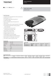
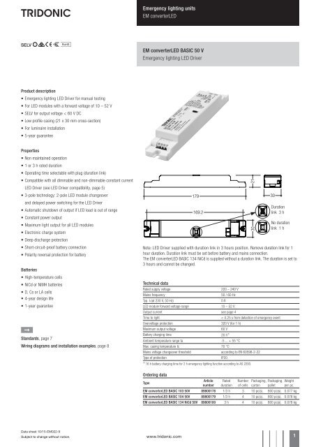
<strong>EM</strong> <strong>converterLED</strong> <strong>BASIC</strong> <strong>50</strong> V<br />
Emergency lighting LED Driver<br />
Product description<br />
• Emergency lighting LED Driver for manual testing<br />
• For LED modules with a forward voltage of 10 – 52 V<br />
• SELV for output voltage < 60 V DC<br />
• Low profile casing (21 x 30 mm cross-section)<br />
• For luminaire installation<br />
• 5-year guarantee<br />
Properties<br />
• Non maintained operation<br />
• 1 or 3 h rated duration<br />
• Operating time selectable with plug (duration link)<br />
• Compatible with all dimmable and non-dimmable constant current<br />
LED Driver (see LED Driver compatibility, page 5)<br />
• 3-pole technology: 2-pole LED module changeover<br />
and delayed power switching for the LED Driver<br />
• Automatic shutdown of output if LED load is out of range<br />
• Constant power output<br />
• Maximum light output for all LED modules<br />
• Electronic charge system<br />
• Deep discharge protection<br />
• Short-circuit-proof battery connection<br />
• Polarity reversal protection for battery<br />
Batteries<br />
• High-temperature cells<br />
• NiCd or NiMH batteries<br />
• D, Cs or LA cells<br />
• 4-year design life<br />
• 1-year guarantee<br />
È<br />
Standards, page 7<br />
Wiring diagrams and installation examples, page 8<br />
179<br />
169.2<br />
21<br />
30<br />
30<br />
Duration<br />
link 3 h<br />
No duration<br />
link 1 h<br />
Note: LED Driver supplied with duration link in 3 hours position. Remove duration link for 1<br />
hour duration. Duration link must be set before battery and mains connection.<br />
The <strong>EM</strong> <strong>converterLED</strong> <strong>BASIC</strong> 134 NiCd is supplied without a duration link. The duration is set to<br />
3 hours and cannot be changed.<br />
Technical data<br />
Rated supply voltage<br />
220 – 240 V<br />
Mains frequency<br />
<strong>50</strong> / 60 Hz<br />
Typ. λ (at 230 V, <strong>50</strong> Hz) 0.6<br />
LED module forward voltage range<br />
10 – 52 V<br />
Output current see page 4<br />
Time to light<br />
< 0.25 s from detection of emergency event<br />
Overvoltage protection 320 V (for 1 h)<br />
Maximum output voltage<br />
60 V<br />
Battery charging time 20 h 1<br />
Ambient temperature range ta -5 ... + 55 °C<br />
Max. casing temperature tc 70 °C<br />
Mains voltage changeover threshold according to EN 60598-2-22<br />
Type of protection<br />
IP20<br />
1<br />
16 h battery charging time for 2 h emergency lighting function according to AS 2293.<br />
Ordering data<br />
Type<br />
Article<br />
number<br />
Rated<br />
duration<br />
Number<br />
of cells<br />
Packaging,<br />
carton<br />
Packaging,<br />
pallet<br />
Weight<br />
per pc.<br />
<strong>EM</strong> <strong>converterLED</strong> <strong>BASIC</strong> 103 <strong>50</strong>V 89800178 1/3 h 3 10 pc(s). 800 pc(s). 0.077 kg<br />
<strong>EM</strong> <strong>converterLED</strong> <strong>BASIC</strong> 104 <strong>50</strong>V 89800179 1/3 h 4 10 pc(s). 800 pc(s). 0.078 kg<br />
<strong>EM</strong> <strong>converterLED</strong> <strong>BASIC</strong> 134 NiCd <strong>50</strong>V 89800180 3 h 4 10 pc(s). 800 pc(s). 0.078 kg<br />
Data sheet 10/15-<strong>EM</strong>022-9<br />
Subject to change without notice.<br />
www.tridonic.com 1
Emergency lighting units<br />
<strong>EM</strong> <strong>converterLED</strong><br />
Specific technical data<br />
Type<br />
Rated duration<br />
Max. output power<br />
Mains current in charging<br />
operation<br />
Rated power in charging<br />
operation<br />
<strong>EM</strong> <strong>converterLED</strong> <strong>BASIC</strong> 103 <strong>50</strong>V<br />
1 h 2.75 W 25 mA 3.0 W<br />
3 h 2.75 W 30 mA 3.7 W<br />
<strong>EM</strong> <strong>converterLED</strong> <strong>BASIC</strong> 104 <strong>50</strong>V<br />
1 h 3.<strong>50</strong> W 27 mA 3.0 W<br />
3 h 3.<strong>50</strong> W 35 mA 4.0 W<br />
<strong>EM</strong> <strong>converterLED</strong> <strong>BASIC</strong> 134 NiCd <strong>50</strong>V 3 h 1.35 W 27 mA 3.0 W<br />
ACCES-<br />
SORIES<br />
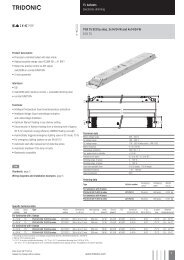
Test switch <strong>EM</strong>3<br />
Product description<br />
• For connection to the emergency lighting unit<br />
• For checking the device function<br />
• Plug connection<br />
Ordering data<br />
Type<br />
Article number<br />
Packaging,<br />
bag<br />
Packaging,<br />
carton<br />
Weight<br />
per pc.<br />
Test switch <strong>EM</strong> 3 89899956 25 pc(s). 200 pc(s). 0.013 kg<br />
ACCESSO-<br />
RIES<br />
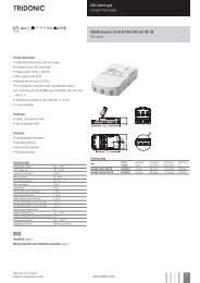
Status indication green LED<br />
Product description<br />
• A green LED indicates that charging current is flowing into the<br />
battery<br />
• Plug connection<br />
Ordering data<br />
Type<br />
Article number<br />
Packaging, Packaging,<br />
bag carton<br />
Weight<br />
per pc.<br />
LED <strong>EM</strong> green, 1.0 m CON 89800269 25 pc(s). 200 pc(s). 0.015 kg<br />
LED <strong>EM</strong> green, HO 1.0 m CON 89800271 25 pc(s). 200 pc(s). 0.015 kg<br />
LED <strong>EM</strong> green, 0.6 m CON 89800472 25 pc(s). 200 pc(s). 0.005 kg<br />
LED <strong>EM</strong> green, HO 0.6 m CON 89800473 25 pc(s). 200 pc(s). 0.005 kg<br />
LED <strong>EM</strong> green, 0.3 m CON 89800270 25 pc(s). 200 pc(s). 0.005 kg<br />
LED <strong>EM</strong> green, HO 0.3 m CON 89800272 25 pc(s). 200 pc(s). 0.005 kg<br />
Data sheet 10/15-<strong>EM</strong>022-9<br />
Subject to change without notice.<br />
www.tridonic.com 2
Emergency lighting units<br />
<strong>EM</strong> <strong>converterLED</strong><br />
Battery selection<br />
<strong>EM</strong> <strong>converterLED</strong> <strong>BASIC</strong>, 1 / 3 h<br />
Type<br />
<strong>EM</strong> <strong>converterLED</strong> <strong>BASIC</strong><br />
103 <strong>50</strong>V<br />
<strong>EM</strong> <strong>converterLED</strong> <strong>BASIC</strong><br />
104 <strong>50</strong>V<br />
<strong>EM</strong> <strong>converterLED</strong><br />
<strong>BASIC</strong> 134 <strong>50</strong>V<br />
Technology and Design<br />
capacity<br />
NiCd 1.6 Ah<br />
Cs cells<br />
Number<br />
of cells<br />
Type<br />
Article no. 89800178 89800179 89800180<br />
Cells 3 cells 4 cells 4 cells<br />
Duration 1 h 3 h 1 h 3 h 3 h<br />
Article no.<br />
Assignable batteries<br />
stick 1 x 3 Accu-NiCd C 3A 89899743 •<br />
stick 1 x 4 Accu-NiCd C 4A 89899692 • •<br />
stick + stick 2 + 2 Accu-NiCd C 4C 89899694 • •<br />
side by side 4 x 1 Accu NiCd C4B 89899693 • •<br />
NiCd 4 Ah<br />
D cells 1 side by side 3 x 1 Accu NiCd 3B 89895976 •<br />
stick 1 x 3 Accu-NiCd 3A 89895960 •<br />
stick 1 x 4 Accu-NiCd 4A 55 89800089 •<br />
side by side 4 x 1 Accu NiCd 4B 89895977 •<br />
stick + stick 2 + 2 Accu-NiCd 4C 89895978 •<br />
NiMH 2 Ah<br />
Cs cells<br />
stick 1 x 3 Accu-NiMH C 3A 89899744 •<br />
stick 1 x 4 Accu-NiMH C 4A 89899700 • •<br />
stick 1 x 3 Accu-NiMH 4Ah 3A CON 89800441 •<br />
NiMH 4 Ah<br />
LA cells<br />
stick 1 x 4 Accu-NiMH 4Ah 4A CON 89800442 •<br />
stick + stick 2 + 2 Accu-NiMH 4Ah 4C CON 89800438 •<br />
1<br />
<strong>50</strong> °C batteries also available (see seperate datasheet at www.tridonic.com).<br />
Battery charge / discharge data<br />
<strong>EM</strong> <strong>converterLED</strong> <strong>BASIC</strong>, 1 / 3 h<br />
Type<br />
<strong>EM</strong> <strong>converterLED</strong> <strong>BASIC</strong><br />
103 <strong>50</strong>V<br />
<strong>EM</strong> <strong>converterLED</strong> <strong>BASIC</strong><br />
104 <strong>50</strong>V<br />
<strong>EM</strong> <strong>converterLED</strong><br />
<strong>BASIC</strong> 134 <strong>50</strong>V<br />
Article no. 89800178 89800179 89800180<br />
Cells 3 cells 4 cells 4 cells<br />
Duration 1 h 3 h 1 h 3 h 3 h<br />
Charging current 105 mA 210 mA 105 mA 210 mA 105 mA<br />
Discharge current 7<strong>50</strong> – 960 mA 7<strong>50</strong> – 960 mA 7<strong>50</strong> – 960 mA 7<strong>50</strong> – 960 mA 290 – 370 mA<br />
Data sheet 10/15-<strong>EM</strong>022-9<br />
Subject to change without notice.<br />
www.tridonic.com 3
Emergency lighting units<br />
<strong>EM</strong> <strong>converterLED</strong><br />
Typ. LED current/voltage characteristics<br />
The LED current in emergency mode is automatically adjusted by the <strong>EM</strong> <strong>converterLED</strong> module based on the<br />
total forward voltage of the LED modules connected and the associated battery.<br />
<strong>EM</strong> <strong>converterLED</strong> <strong>BASIC</strong> 103 <strong>50</strong>V<br />
Article number: 89800178<br />
3.6 V battery voltage<br />
7<strong>50</strong> – 960 mA battery discharge current (tolerance)<br />
<strong>EM</strong> <strong>converterLED</strong> <strong>BASIC</strong> 104 <strong>50</strong>V<br />
Article number: 89800179<br />
4.8 V battery voltage<br />
7<strong>50</strong> – 960 mA battery discharge current (tolerance)<br />
300<br />
270<br />
240<br />
210<br />
400<br />
3<strong>50</strong><br />
300<br />
LED current [mA]<br />
180<br />
1<strong>50</strong><br />
120<br />
90<br />
LED current [mA]<br />
2<strong>50</strong><br />
200<br />
1<strong>50</strong><br />
60<br />
30<br />
100<br />
0<br />
10 15 20 25 30 35 40 45 <strong>50</strong> 55<br />
V LED<br />
[V]<br />
<strong>50</strong><br />
10 15 20 25 30 35 40 45 <strong>50</strong> 55<br />
V LED<br />
[V]<br />
LED peak current at start in emergency mode – 3 cells<br />
Voltage Inrush current Duration<br />
16.0 V 478 mA 11.0 ms<br />
18.6 V 439 mA 9.6 ms<br />
21.2 V 407 mA 8.2 ms<br />
23.7 V 377 mA 7.8 ms<br />
26.3 V 356 mA 7.0 ms<br />
31.4 V 315 mA 6.3 ms<br />
33.9 V 302 mA 5.6 ms<br />
36.4 V 290 mA 5.2 ms<br />
38.9 V 275 mA 4.7 ms<br />
41.5 V 262 mA 4.3 ms<br />
44.0 V 252 mA 3.9 ms<br />
46.6 V 244 mA 3.6 ms<br />
49.0 V 234 mA 3.5 ms<br />
51.6 V 228 mA 3.3 ms<br />
LED peak current at start in emergency mode – 4 cells<br />
Voltage Inrush current Duration<br />
16.2 V 466 mA 17.0 ms<br />
18.8 V 435 mA 13.4 ms<br />
21.3 V 407 mA 11.5 ms<br />
23.9 V 385 mA 10.8 ms<br />
26.5 V 365 mA 9.5 ms<br />
31.6 V 333 mA 7.8 ms<br />
34.2 V 321 mA 6.5 ms<br />
36.7 V 308 mA 6.0 ms<br />
39.3 V 295 mA 5.5 ms<br />
41.8 V 286 mA 5.3 ms<br />
44.3 V 277 mA 5.1 ms<br />
46.9 V 270 mA 4.9 ms<br />
49.4 V 262 mA 4.4 ms<br />
51.9 V 255 mA 4.2 ms<br />
Note: LED peak current measured at the max. battery discharge current and at a max. battery voltage of 4.5 V (3 cells) or 6 V (4 cells).<br />
Data sheet 10/15-<strong>EM</strong>022-9<br />
Subject to change without notice.<br />
www.tridonic.com 4
Emergency lighting units<br />
<strong>EM</strong> <strong>converterLED</strong><br />
<strong>EM</strong> <strong>converterLED</strong> <strong>BASIC</strong> 134 NICD <strong>50</strong>V<br />
Article number: 89800180<br />
4.8 V battery voltage<br />
290 – 370 mA battery discharge current (tolerance)<br />
1<strong>50</strong><br />
135<br />
120<br />
105<br />
LED current [mA]<br />
90<br />
75<br />
60<br />
45<br />
LED current at nominal battery voltage and<br />
min. battery discharge current<br />
LED current at nominal battery voltage and<br />
max. battery discharge current<br />
30<br />
15<br />
10 15 20 25 30 35 40 45 <strong>50</strong> 55<br />
V LED<br />
[V]<br />
LED peak current at start in emergency mode – 4 cells<br />
Voltage Inrush current Duration<br />
15.8 V 406 mA 14.5 ms<br />
18.3 V 378 mA 12.5 ms<br />
20.8 V 359 mA 10.8 ms<br />
23.4 V 346 mA 9.7 ms<br />
25.9 V 330 mA 9.0 ms<br />
28.4 V 316 mA 8.1 ms<br />
30.9 V 308 mA 7.8 ms<br />
33.5 V 295 mA 7.0 ms<br />
36.0 V 287 mA 6.3 ms<br />
38.5 V 275 mA 5.9 ms<br />
41.0 V 267 mA 5.7 ms<br />
43.5 V 258 mA 5.1 ms<br />
46.0 V 252 mA 4.2 ms<br />
48.5 V 244 mA 4.0 ms<br />
Data sheet 10/15-<strong>EM</strong>022-9<br />
Subject to change without notice.<br />
www.tridonic.com 5
Emergency lighting units<br />
<strong>EM</strong> <strong>converterLED</strong><br />
Isolation and electric strength testing of luminaires<br />
Electronic LED Drivers can be damaged by high voltage. This has to be considered<br />
during the routine testing of the luminaires in production.<br />
According to IEC 60598-1 Annex Q (informative only!) or ENEC 303-Annex A, each<br />
luminaire should be submitted to an isolation test with <strong>50</strong>0 VDC for 1 second. This<br />
test voltage should be connected between the interconnected phase and neutral<br />
terminals and the earth terminal. The isolation resistance must be at least 2 MΩ.<br />
As an alternative, IEC 60598-1 Annex Q describes a test of the electrical strength<br />
with 1,<strong>50</strong>0 VAC (or 1,414 x 1,<strong>50</strong>0 VDC). To avoid damage to the electronic devices<br />
this test must not be conducted.<br />
Technical data batteries<br />
Accu-NiCd<br />
Case temperature range<br />
to ensure 4 years design life<br />
4.2 / 4.5 Ah D +5 °C to +55 °C<br />
1.6 Cs +5 °C to +<strong>50</strong> °C<br />
Battery voltage/cell<br />
1.2 V<br />
Single cell dimensions<br />
4.2/ 4.5 Ah D<br />
Diameter<br />
32.5 mm<br />
Height<br />
60.5 mm<br />
1.6 Ah Cs<br />
Diameter<br />
22.5 mm<br />
Height<br />
42.5 mm<br />
Capacity D<br />
4.2 / 4.5 Ah<br />
Capacity Cs<br />
1.6 Ah<br />
Max. short term temperature (reduced life-time) 70 °C<br />
Max. number discharge cycles<br />
Packing quantity<br />
4 cycles per year plus<br />
4 cycles during<br />
comissioning<br />
5 pcs. per carton<br />
Accu-NiMh<br />
Case temperature range<br />
to ensure 4 years design life<br />
2.0 Ah Cs +5 °C to +55 °C<br />
4.0 Ah LA +5 °C to +40 °C<br />
Battery voltage<br />
1.2 V<br />
Single cell dimensions<br />
2.0 Ah Cs<br />
Diameter<br />
22 mm<br />
Height<br />
42.5 mm<br />
4.0 Ah LA<br />
Diameter<br />
18.3 mm<br />
Height<br />
90 mm<br />
Capacity Cs / LA<br />
2.0 Ah / 4.0 Ah<br />
Max. short term temperature (reduced life-time) 70 °C<br />
Max. number discharge cycles 2.0 Ah Cs<br />
Max. number discharge cycles 4.0 Ah LA<br />
Packing quantity<br />
4 cycles per year plus<br />
4 cycles during<br />
comissioning<br />
2 cycles per year plus<br />
4 cycles during<br />
comissioning<br />
5 pcs. per carton<br />
Storage, installation and commissioning<br />
Relevant information about storage conditions, installation and commissioning are<br />
provided in the battery datasheets.<br />
LED Driver compatibility<br />
The <strong>EM</strong> <strong>converterLED</strong> emergency unit use 3 pole technology and is compatible<br />
with most LED Drivers on the market, however it is important to check that the<br />
rating of the LED Driver does not exceed the values specified below:<br />
• The max. allowed output current rating of the associated LED Driver is 2.4 A<br />
peak (current rating of switching relays of <strong>EM</strong> <strong>converterLED</strong>)<br />
• The max. allowed inrush current rating of the associated LED Driver is 60 A<br />
peak for 1 ms (inrush current rating of switching relay of <strong>EM</strong> <strong>converterLED</strong>)<br />
• The max. allowed output voltage of the associated LED Driver applied to the<br />
<strong>EM</strong> <strong>converterLED</strong> output is 4<strong>50</strong>V (voltage withstand between adjacent contact<br />
of the single switching relay of the <strong>EM</strong> <strong>converterLED</strong>)<br />
• The max. allowed power rating of the associated LED Driver is 80 W in<br />
operation<br />
Life-time<br />
Average life-time <strong>50</strong>,000 hours under rated conditions with a failure rate of less<br />
than 10 %. Average failure rate of 0.2 % per 1000 operating hours.<br />
Maximum lead length<br />
LED 3 m 1<br />
Status indication LED 1 m<br />
Batteries<br />
1.3 m<br />
1<br />
Note: The length of LED leads to the LED module must not be exceeded. Note that the length of the<br />
<strong>EM</strong> <strong>converterLED</strong> leads is added to the length of the leads from the LED Driver to the <strong>EM</strong> <strong>converterLED</strong><br />
module when considering max. permitted lead length of the LED Driver. Leads should always be kept<br />
as short as possible.<br />
Mechanical details<br />
Casing manufactured from polycarbonate.<br />
Glow-wire test according to EN 61347-1 with increased temperature of 960 °C<br />
passed.<br />
LED status indicator<br />
• Green<br />
• Mounting hole 6.5 mm dia<br />
• Lead length 0.3 m / 1.0 m<br />
• Insulation rating: 90 °C<br />
• Plug connection<br />
Test switch<br />
• Mounting hole 7.0 mm dia<br />
• Lead length 0.55 m<br />
• Plug connection<br />
Battery leads<br />
• Quantity: 1 red and 1 black<br />
• Length: 1.3 m<br />
• Wire type: 0.5 mm 2 solid conductor<br />
• Insulation rating: 90 °C<br />
Battery end termination<br />
Push on 4.8 mm receptacle to suit battery<br />
spade fitted with insulating cover<br />
Module end termination<br />
8.0 mm stripped insulation<br />
Two-piece batteries are supplied with a 200 mm lead with 4.8 mm receptacle at<br />
each end and insulting covers to connect the separate sticks together.<br />
Data sheet 10/15-<strong>EM</strong>022-9<br />
Subject to change without notice.<br />
www.tridonic.com 6
Emergency lighting units<br />
<strong>EM</strong> <strong>converterLED</strong><br />
Electrical connections<br />
Duration link selection<br />
Wiring<br />
LED module/LED Driver/supply<br />
Duration<br />
3 h<br />
Usage duration link<br />
wire preparation:<br />
0.5 – 1.5 mm²<br />
With link<br />
8 – 9 mm<br />
1 h<br />
Without link<br />
Emergency lighting LED Driver supplied with duration link in 3 hours position.<br />
Loosen wire through twisting<br />
and pulling or using a Ø 1 mm<br />
release tool<br />
The position of the link will only be read on first power up. If it is changed<br />
afterwards both the battery and mains supply must be disconnected for 10<br />
seconds to enable the <strong>EM</strong> <strong>converterLED</strong> to read the new link position on<br />
reconnection of the battery and mains. It will lead to a false battery failure<br />
indication if the link is changed after installation without this reset.<br />
Wiring type and cross section<br />
Solid wire with a cross section of 0.5 – 1.5 mm². Strip 8 – 9 mm of insulation<br />
from the cables to ensure perfect operation of terminals.<br />
Batteries<br />
Connection method: 4.8 x 0.5 mm spade tag welded to end of cell.<br />
For stick packs this connection is accessible after the battery caps have been<br />
fitted.<br />
To inhibit inverter operation disconnect the batteries by removing the connector<br />
from the battery spade tag.<br />
For battery data see separate data sheet.<br />
Phase to phase isolation<br />
The use of different phases for switched line and unswitched line is permitted.<br />
Standards<br />
• according to EN <strong>50</strong>172<br />
• according to EN 60598-2-22<br />
• EN 61347-1:2008+A2:2013<br />
• EN 61347-2-13<br />
• EN 61347-2-7<br />
• EN 5<strong>50</strong>15<br />
• EN 61000-3-2<br />
• EN 61000-3-3<br />
• EN 61547<br />
• EN 60068-2-64<br />
• EN 60068-2-29<br />
• EN 60068-2-30<br />
• EN 62384<br />
Meaning of marking<br />
Double or reinforced insulation for built-in electronic LED Drivers<br />
Data sheet 10/15-<strong>EM</strong>022-9<br />
Subject to change without notice.<br />
www.tridonic.com 7
Emergency lighting units<br />
<strong>EM</strong> <strong>converterLED</strong><br />
Wiring guidelines<br />
• The LED terminals, battery, indicator LED and test switch terminals are classified<br />
as SELV (output voltage < 60 V DC). Keep the wiring of the input terminals<br />
separated from the wiring of the SELV equivalent terminals or consider special<br />
wiring (double insulation, 6 mm creepage and clearance) when these connections<br />
should be kept SELV.<br />
• The output to the LED is DC but has high frequency content, which should be<br />
considered for good <strong>EM</strong>C compliance.<br />
• LED leads should be separated from the mains connections and wiring for good<br />
<strong>EM</strong>C performance.<br />
• Maximum lead length on the LED terminals is 3 m. For a good <strong>EM</strong>C<br />
performance keep the LED wiring as short as possible.<br />
• Maximum lead length for the Test switch and Indicator LED connection is 1 m.<br />
The test switch and Indicator LED wiring should be separated from the LED leads<br />
to prevent noise coupling.<br />
• Battery leads are specified with 0.5 mm cross section and a length of 1.3 m<br />
To ensure that a luminaire containing LED emergency units complies with EN 5<strong>50</strong>15<br />
for radio frequency conducted interference in both normal and emergency mode it is<br />
essential to follow good practice in the wiring layout.<br />
Within the luminaire the switched and unswitched <strong>50</strong> Hz supply wiring must be<br />
routed as short as possible and be kept as far away as possible from the LED leads.<br />
Through wiring may affect the emc performance of the luminaire.<br />
The length of LED leads must not be exceeded. Note that the length of the<br />
<strong>EM</strong> <strong>converterLED</strong> leads is added to the length of the leads from the LED Driver to the<br />
<strong>EM</strong> <strong>converterLED</strong> module when considering max. permitted lead length of the LED<br />
Driver.<br />
Maximum loading of automatic circuit breakers<br />
Automatic circuit breaker type B10 B13 B16 B20 C10 C13 C16 C20 Inrush current<br />
Installation Ø 1.5 mm 2 1.5 mm 2 1.5 mm 2 2.5 mm 2 1.5 mm 2 1.5 mm 2 1.5 mm 2 2.5 mm 2 I max<br />
time<br />
<strong>EM</strong> <strong>converterLED</strong> 103 <strong>BASIC</strong> <strong>50</strong>V 90 130 130 130 180 260 260 260 10 A 120 μs<br />
<strong>EM</strong> <strong>converterLED</strong> 104 <strong>BASIC</strong> <strong>50</strong>V 90 130 130 130 180 260 260 260 10 A 120 μs<br />
Wiring diagrams<br />
One or more LED modules with a total forward voltage of 10 to 52 V can be connected to the <strong>EM</strong> <strong>converterLED</strong><br />
<strong>50</strong>V module. These LED module(s), marked with “Emergency” are operated in emergency mode from the<br />
associated battery. In normal mains mode all LED modules are operated by the mains LED Driver.<br />
<strong>EM</strong> <strong>converterLED</strong> <strong>BASIC</strong> with one LED module for non-maintained emergency operation<br />
Not connected<br />
Not connected<br />
Neutral<br />
Un-Switched Line<br />
L out<br />
L in<br />
N<br />
L<br />
Control gear<br />
LED<br />
<strong>EM</strong> ConverterLED LED<br />
<strong>BASIC</strong> Control gear<br />
Battery<br />
Battery<br />
+<br />
+<br />
+<br />
–<br />
–<br />
+<br />
– –<br />
LED Module<br />
Emergency<br />
Test<br />
switch<br />
Indicator<br />
LED<br />
P<br />
O<br />
<strong>EM</strong> <strong>converterLED</strong> <strong>BASIC</strong> with a standard LED Driver and one LED module for mains and emergency operation<br />
Switched Line out<br />
Switched Line in<br />
Neutral<br />
Un-Switched Line<br />
L out<br />
L in<br />
N<br />
L<br />
Control gear<br />
LED<br />
<strong>EM</strong> ConverterLED LED<br />
<strong>BASIC</strong> Control gear<br />
Battery<br />
Battery<br />
+<br />
+<br />
+<br />
–<br />
–<br />
+<br />
– –<br />
LED Module<br />
Emergency<br />
Test<br />
switch<br />
Indicator<br />
LED<br />
P<br />
O<br />
+<br />
Neutral<br />
L<br />
N<br />
LED control gear<br />
max. 80 W in operation<br />
–<br />
Data sheet 10/15-<strong>EM</strong>022-9<br />
Subject to change without notice.<br />
www.tridonic.com 8
Emergency lighting units<br />
<strong>EM</strong> <strong>converterLED</strong><br />
<strong>EM</strong> <strong>converterLED</strong> <strong>BASIC</strong> with a standard LED Driver and series operation of LED modules<br />
Switched Line out<br />
Switched Line in<br />
Neutral<br />
Un-Switched Line<br />
L out<br />
L in<br />
N<br />
L<br />
Control gear<br />
LED<br />
<strong>EM</strong> ConverterLED LED<br />
<strong>BASIC</strong> Control gear<br />
Battery<br />
Battery<br />
+<br />
+<br />
+<br />
–<br />
–<br />
+<br />
– –<br />
LED Module<br />
Emergency<br />
Test<br />
switch<br />
Indicator<br />
LED<br />
P<br />
O<br />
+<br />
+<br />
Neutral<br />
L<br />
N<br />
LED control gear<br />
max. 80 W in operation<br />
LED Module<br />
–<br />
–<br />
One LED module is operated in emergency mode.<br />
All LED modules are operated in mains mode.<br />
+<br />
–<br />
LED Module<br />
<strong>EM</strong> <strong>converterLED</strong> <strong>BASIC</strong> with a standard LED Driver and series operation of LED modules<br />
Switched Line out<br />
Switched Line in<br />
Neutral<br />
Un-Switched Line<br />
L out<br />
L in<br />
N<br />
L<br />
Control gear<br />
LED<br />
<strong>EM</strong> ConverterLED LED<br />
<strong>BASIC</strong> Control gear<br />
Battery<br />
Battery<br />
+<br />
+<br />
+<br />
–<br />
–<br />
+<br />
– –<br />
LED Module<br />
Emergency<br />
Test<br />
switch<br />
Indicator<br />
LED<br />
P<br />
O<br />
+<br />
LED Module<br />
Emergency<br />
–<br />
+<br />
Neutral<br />
L<br />
N<br />
LED control gear<br />
max. 80 W in operation<br />
+<br />
–<br />
LED Module<br />
–<br />
+<br />
Two or more LED modules are operated in emergency mode.<br />
All LED modules are operated in mains mode.<br />
–<br />
LED Module<br />
Data sheet 10/15-<strong>EM</strong>022-9<br />
Subject to change without notice.<br />
www.tridonic.com 9
Emergency lighting units<br />
<strong>EM</strong> <strong>converterLED</strong><br />
<strong>EM</strong> <strong>converterLED</strong> <strong>BASIC</strong> with a standard LED Driver and parallel operation of LED modules<br />
Switched Line out<br />
Switched Line in<br />
Neutral<br />
Un-Switched Line<br />
L out<br />
L in<br />
N<br />
L<br />
Control gear<br />
LED<br />
<strong>EM</strong> ConverterLED LED<br />
<strong>BASIC</strong> Control gear<br />
Battery<br />
Battery<br />
+<br />
+<br />
+<br />
–<br />
–<br />
+<br />
– –<br />
LED Module<br />
Emergency<br />
Test<br />
switch<br />
Indicator<br />
LED<br />
P<br />
O<br />
Neutral<br />
L<br />
N<br />
LED control gear<br />
max. 80 W in operation<br />
+<br />
+<br />
LED Module<br />
–<br />
–<br />
One LED module is operated in emergency mode.<br />
All LED modules are operated in mains mode.<br />
+<br />
–<br />
LED Module<br />
<strong>EM</strong> <strong>converterLED</strong> <strong>BASIC</strong> with a standard LED Driver and parallel operation of LED modules<br />
Switched Line out<br />
Switched Line in<br />
Neutral<br />
Un-Switched Line<br />
L out<br />
L in<br />
N<br />
L<br />
Control gear<br />
LED<br />
<strong>EM</strong> ConverterLED LED<br />
<strong>BASIC</strong> Control gear<br />
Battery<br />
Battery<br />
+<br />
+<br />
+<br />
–<br />
–<br />
+<br />
– –<br />
LED Module<br />
Emergency<br />
Test<br />
switch<br />
Indicator<br />
LED<br />
P<br />
O<br />
+<br />
LED Module<br />
Emergency<br />
–<br />
+<br />
+<br />
Neutral<br />
L<br />
N<br />
LED control gear<br />
max. 80 W in operation<br />
LED Module<br />
–<br />
–<br />
+<br />
Two or more LED modules are operated in emergency mode.<br />
All LED modules are operated in mains mode.<br />
–<br />
LED Module<br />
Data sheet 10/15-<strong>EM</strong>022-9<br />
Subject to change without notice.<br />
www.tridonic.com 10
Emergency lighting units<br />
<strong>EM</strong> <strong>converterLED</strong><br />
Additional information<br />
Additional technical information at<br />
www.tridonic.com → Technical Data<br />
Guarantee conditions at<br />
www.tridonic.com → Services<br />
No warranty if device was opened.<br />
Data sheet 10/15-<strong>EM</strong>022-9<br />
Subject to change without notice.<br />
www.tridonic.com 11