PDF (154kB) - Helmholtz-Zentrum Berlin
PDF (154kB) - Helmholtz-Zentrum Berlin
PDF (154kB) - Helmholtz-Zentrum Berlin

You also want an ePaper? Increase the reach of your titles
YUMPU automatically turns print PDFs into web optimized ePapers that Google loves.
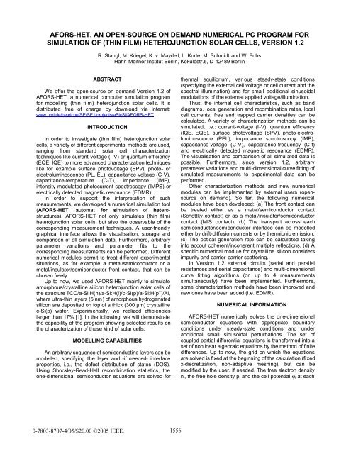
AFORS-HET, AN OPEN-SOURCE ON DEMAND NUMERICAL PC PROGRAM FOR<br />
SIMULATION OF (THIN FILM) HETEROJUNCTION SOLAR CELLS, VERSION 1.2<br />
R. Stangl, M. Kriegel, K. v. Maydell, L. Korte, M. Schmidt and W. Fuhs<br />
Hahn-Meitner Institut <strong>Berlin</strong>, Kekuléstr.5, D-12489 <strong>Berlin</strong><br />
ABSTRACT<br />
We offer the open-source on demand Version 1.2 of<br />
AFORS-HET, a numerical computer simulation program<br />
for modelling (thin film) heterojunction solar cells. It is<br />
distributed free of charge by download via internet:<br />
www.hmi.de/bereiche/SE/SE1/projects/aSicSi/AFORS-HET<br />
INTRODUCTION<br />
In order to investigate (thin film) heterojunction solar<br />
cells, a variety of different experimental methods are used,<br />
ranging from standard solar cell characterization<br />
techniques like current-voltage (I-V) or quantum efficiency<br />
(EQE, IQE) to more advanced characterization techniques<br />
like for example surface photovoltage (SPV), photo- or<br />
electroluminescence (PL, EL), capacitance-voltage (C-V),<br />
capacitance-temperature (C-T), impedance (IMP),<br />
intensity modulated photocurrent spectroscopy (IMPS) or<br />
electrically detected magnetic resonance (EDMR).<br />
In order to support the interpretation of such<br />
measurements, we developed a numerical simulation tool<br />
(AFORS-HET, automat for simulation of heterostructures).<br />
AFORS-HET not only simulates (thin film)<br />
heterojunction solar cells, but also the observable of the<br />
corresponding measurement techniques. A user-friendly<br />
graphical interface allows the visualisation, storage and<br />
comparison of all simulation data. Furthermore, arbitrary<br />
parameter variations and parameter fits to the<br />
corresponding measurements can be performed. Different<br />
numerical modules permit to treat different experimental<br />
situations, as for example a metal/semiconductor or a<br />
metal/insulator/semiconductor front contact, that can be<br />
chosen freely.<br />
Up to now, we used AFORS-HET mainly to simulate<br />
amorphous/crystalline silicon heterojunction solar cells of<br />
the structure TCO/a-Si:H(n)/a-Si:H(i)/c-Si(p)/a-Si:H(p + )/Al,<br />
where ultra-thin layers (5 nm) of amorphous hydrogenated<br />
silicon are deposited on top of a thick (300 µm) crystalline<br />
c-Si(p) wafer. Experimentally, we realized efficiencies<br />
larger than 17% [1]. In the following, we will demonstrate<br />
the capability of the program showing selected results on<br />
the characterization of these kind of solar cells.<br />
MODELLING CAPABILITIES<br />
An arbitrary sequence of semiconducting layers can be<br />
modelled, specifying the layer and -if needed- interface<br />
properties, i.e., the defect distribution of states (DOS).<br />
Using Shockley-Read-Hall recombination statistics, the<br />
one-dimensional semiconductor equations are solved for<br />
0-7803-8707-4/05/$20.00 ©2005 IEEE.<br />
1556<br />
thermal equilibrium, various steady-state conditions<br />
(specifying the external cell voltage or cell current and the<br />
spectral illumination) and for small additional sinusoidal<br />
modulations of the external applied voltage/illumination.<br />
Thus, the internal cell characteristics, such as band<br />
diagrams, local generation and recombination rates, local<br />
cell currents, free and trapped carrier densities can be<br />
calculated. A variety of characterization methods can be<br />
simulated, i.e.: current-voltage (I-V), quantum efficiency<br />
(IQE, EQE), surface photovoltage (SPV), photo-electroluminescence<br />
(PEL), impedance spectroscopy (IMP),<br />
capacitance-voltage (C-V), capacitance-frequency (C-f)<br />
and electrically detected magnetic resonance (EDMR).<br />
The visualisation and comparison of all simul ated data is<br />
possible. Furthermore, since version 1.2, arbitrary<br />
parameter variations and multi-dimensional curve fitting of<br />
simulated measurements to experimental data can be<br />
performed.<br />
Other characterization methods and new numerical<br />
modules can be implemented by external users (opensource<br />
on demand). So far, the following numerical<br />
modules have been developed: (a) The front contact can<br />
be treated either as a metal/semiconductor contact<br />
(Schottky contact) or as a metal/insulator/semiconductor<br />
contact (MIS contact). (b) The transport across each<br />
semiconductor/semiconductor interface can be modelled<br />
either by drift-diffusion currents or by thermionic emission.<br />
(c) The optical generation rate can be calculated taking<br />
into accout coherent/incoherent multiple reflections. (d) A<br />
specific numerical module for crystalline silicon considers<br />
impurity and carrier-carrier scattering.<br />
In Version 1.2 external circuits (serial and parallel<br />
resistances and serial capacitance) and multi-dimensional<br />
curve fitting algorithms (on up to 4 measurements<br />
simultaneously) have been implemented. Furthermore,<br />
some characterization methods have been improved and<br />
new ones have been added (i.e. EDMR).<br />
NUMERICAL INFORMATION<br />
AFORS-HET numerically solves the one-dimensional<br />
semiconductor equations with appropriate boundary<br />
conditions under steady-state conditions and under<br />
additional small sinusoidal perturbations. The set of<br />
coupled partial differential equations is transformed into a<br />
set of nonlinear algebraic equations by the method of finite<br />
differences. Up to now, the grid on which the equations<br />
are solved is fixed at the beginning of the calculation (fixed<br />
x-discretization, non-adaptive meshing), but can be<br />
modified by the user, if needed. The free electron density<br />
ni, the free hole density pi and the cell potential ϕi at each
grid point are used as independent variables. All other<br />
variables in the discretized differential equations and<br />
boundary conditions are expressed in such a way that<br />
they only depend on these independent variables. The<br />
resulting nonlinear equations are solved using the<br />
Newton-Raphson iteration scheme thereby requiring a<br />
good starting solution. If equilibrium conditions are<br />
chosen, AFORS-HET can supply a starting solution from<br />
analytical approximations. Otherwise the last calculated<br />
solution serves as a starting solution for the new boundary<br />
conditions to be solved. Alternatively, starting solutions<br />
can be saved/loaded. For detailed information see [2, 3].<br />
With the ability to calculate internal cell characteristics<br />
(band diagrams, local generation and recombination rates,<br />
local cell currents, carrier densities and phase shifts)<br />
under various specified external boundary conditions,<br />
measurement methods can be defined by a specific<br />
variation of the external boundary conditions and some<br />
additional post-processing data analysis.<br />
SELECTED RESULTS<br />
In the following, we will demonstrate the capability of<br />
the program showing selected results on the simulation of<br />
TCO/a-Si:H(n)/c-Si(p)/Al silicon heterojunction solar cells.<br />
Fig. 1: Screenshots of typical input specifications used for<br />
the simulation of TCO/a-Si:H(n)/c-Si(p)/Al heterojunction<br />
solar cells. (left) layer sequence, (right) DOS of the<br />
a-Si:H(n) layer and the a-Si:H(n)/c-Si interface.<br />
Before the calculation, an appropriate sequence of<br />
semiconducting layers and interfaces has to be defined.<br />
For the shown example, the corresponding semiconductor<br />
properties, namely the a-Si:H(n) thin-film emitter and the<br />
c-Si(p) silicon wafer, must be stated. Additionally, the<br />
defect distribution of states (DOS) has to be specified for<br />
all layers and, if needed, for the interfaces. Furthermore,<br />
the boundary contacts have to be specified: For the<br />
chosen example, the TCO layer is modelled as an optical<br />
layer (specifying the measured reflectivity and absorption).<br />
The TCO/a-Si:H(n) contact is assumed to be depleted,<br />
whereas the measured barrier height of the contact serves<br />
as an input parameter. For the sake of simplicity, the<br />
1557<br />
c-Si(p)/Al back contact is assumed to be flatband. Some<br />
screenshots of AFORS-HET input are presented in Fig.1.<br />
The DOS of the a-Si:H/c-Si interface states is<br />
assumed to be constant within the bandgap, with a<br />
donator/acceptor behavior in the lower/upper part of the<br />
a-Si:H band gap, respectively (compare Fig.1).<br />
In order to specify the DOS for the thin film a-Si:H<br />
layers, we use photoelectron yield spectroscopy with UV<br />
light excitation (UV-PEYS). Thus, the position of the Fermi<br />
energy, the density of occupied states in the band gap and<br />
the valence band close to the band edge can be<br />
measured. Details of the experimental method can be<br />
found in [4]. As an example, the measured defect<br />
distribution of occupied states for a nominal intrinsic and a<br />
n-doped a-Si:H layer is shown in Fig. 2. The measured<br />
valence band tail, i.e. the Urbach energy, and the<br />
measured occupied dangling bond distribution are used as<br />
direct input parameters in AFORS-HET. However, the<br />
density of unoccupied states, i.e., the Urbach energy of<br />
the conduction band tail, have to be guessed.<br />
Density of states N(E) [cm -3 eV -1 ]<br />
10 22<br />
10 21<br />
10 20<br />
10 19<br />
10 18<br />
10 17<br />
10 16<br />
E V<br />
substrate p-Si (111), 75-125 Ωcm<br />
a-Si:H (PE-CVD): d=10 nm, T dep =200°C<br />
n-type (2×10 4 ppm PH 3 )<br />
i-type nominal intrinsic<br />
-0,4 0,0 0,4 0,8 1,2 1,6<br />
Energy E-E [eV] V<br />
Fig. 2: Measured photoelectron yield spectroscopy data<br />
for nominal intrinsic and n-doped a-Si:H. The resulting<br />
DOS of the thin amorphous silicon layers is used as a<br />
input in AFORS-HET (inset).<br />
After the specification of all internal cell parameters,<br />
one has to to define the external parameters (temperature,<br />
illumination and external cell voltage or cell current<br />
through the boundary). Then, the internal cell<br />
characteristics (band diagrams, local generation and<br />
recombination rates, local cell curents, local free and<br />
trapped carrier densities) and the resulting total cell<br />
current or cell voltage can be calculated.<br />
As an example, the room temperature equilibrium<br />
band diagrams (no illumination, zero external cell voltage)<br />
of a TCO/a-Si:H(n)/a-Si:H(i)/c-Si(p)/Al solar cell, assuming<br />
two different TCO/a-Si:H(n) barrier heights, Vbi of 0 and<br />
0.4 eV, are shown in Fig.3. The TCO/a-Si:H(n) contact<br />
critically influences the solar cell performance. If ultra-thin<br />
layers of amorphous silicon are used (thickness < 10 nm),<br />
a depleted contact changes the band bending in the<br />
crystalline silicon absorber (see Fig.3). This will<br />
significantly reduce the open-circuit voltage of the solar<br />
cell (see Fig.4 and Fig.5).<br />
E f<br />
E f<br />
E C
Energy: E [eV]<br />
1,00<br />
0,75<br />
0,50<br />
0,25<br />
0,00<br />
-0,25<br />
-0,50<br />
-0,75<br />
-1,00<br />
-1,25<br />
-1,50<br />
a-Si:H(n) / a-Si:H(i) / c-S i(p)<br />
0.4 eV<br />
0 eV<br />
V bi<br />
0.4 eV<br />
0 eV<br />
1x10 -7 1x10 -6 1x10 -5 1x10 -4 1x10 -3 1x10 -2<br />
Cell Position: x [cm]<br />
Fig. 3: Simulated equilibrium band diagrams of a<br />
TCO/5nm_a-Si:H(n)/5nm_a-Si:H(i)/c-Si(p)/Al solar cell for<br />
a TCO/a-Si:H(n) barrier height Vbi of 0 eV and 0.4 eV.<br />
V OC [mV]<br />
645<br />
640<br />
635<br />
630<br />
625<br />
620<br />
615<br />
TCO/a-Si(n)<br />
barrier height<br />
straight: V = 0.4 eV<br />
bi<br />
dotted: V = 0 eV<br />
bi<br />
V bi = 0 eV<br />
V bi = 0.4 eV<br />
2 4 6 8 10 12 14 16 18 20 22<br />
emitter thickness [nm]<br />
32<br />
31<br />
30<br />
29<br />
28<br />
E C<br />
E F<br />
E V<br />
i [mA/cm<br />
SC 2<br />
]<br />
Fig. 4: Simulated open-circuit voltage and short-circuit<br />
current of TCO/a-Si:H(n)/c-Si(p)/Al solar cells as a function<br />
of the a-Si:H(n) emitter thickness, assuming a TCO/<br />
a-Si:H(n) barrier height of 0 eV and 0.4 eV.<br />
V OC [mV]<br />
645<br />
640<br />
635<br />
630<br />
625<br />
620<br />
615<br />
2 4 6 8 10 12 14 16 18 20 22<br />
emitter thickness [nm]<br />
32<br />
31<br />
30<br />
29<br />
28<br />
i SC [mA/cm 2 ]<br />
Fig. 5: Measured open-circuit voltage and short circuit<br />
current of TCO/a-Si:H(n)/c-Si(p)/Al solar cells as a function<br />
of the a-Si:H(n) emitter thickness.<br />
1558<br />
That means, there exists an optimum emitter<br />
thickness, depending on the TCO/a-Si:H(n) front contact.<br />
A thick emitter, on the one hand, results in a loss in shortcircuit<br />
current, as the recombination in a-Si:H(n) is quite<br />
high. On the other hand, if the emitter gets too thin, there<br />
is a significant loss in open-circuit voltage due to the<br />
TCO/a-Si:H(n) contact.<br />
This finding is presented in Fig.4, where the simulated<br />
open-circuit voltage, Voc, and short-circuit current, Isc, of<br />
TCO/a-Si:H(n)/c-Si(p)/Al solar cells are plotted as a<br />
function of the a-Si:H(n) emitter thickness. If there is no<br />
TCO/a-Si:H(n) barrier height (ohmic contact, Vbi = 0 eV),<br />
the a-Si:H(n) emitter should be deposited as thin as<br />
technologically possible, see Fig.4. However, if a barrier<br />
height is assumed, Voc suddenly drops at a certain emitter<br />
thickness (see Fig.4). The sudden drop of Voc is also<br />
observed experimentally (see Fig.5).<br />
Internal photoemission and surface photovoltage<br />
measurements suggest that the TCO/a-Si:H(n) contact is<br />
depleted [5, 11]. From the simulation, an optimum emitter<br />
thickness of roughly 7 nm is found for Vbi = 0.4 eV. For a<br />
lower/higher Vbi the optimum emitter thickness is<br />
accordingly lower/higher, respectively.<br />
As already mentioned, AFORS-HET can also simulate<br />
measurement methods, i.e. current-voltage (I-V), quantum<br />
efficiency (IQE, EQE), surface photovoltage (SPV), photoelectro-luminescence<br />
(PEL), capacitance-voltage (C-V),<br />
capacitance-temperature (C-T), impedance (IMP) and<br />
electrically detected magnetic resonance (EDMR). If one<br />
simulates such a measurement, the external parameters<br />
of the program (temperature, illumination, cell voltage or<br />
total cell current) are varied in accordance to the specific<br />
measurement set-up. Arbitrary internal or external cell<br />
parameters are collected and post-processed in order to<br />
produce the desired measurement output. Version 1.2 of<br />
AFORS-HET is modulized in a way, that other<br />
measurement methods can be implemented or personally<br />
adapted by external users (open-source on demand).<br />
As an example, the simulation of internal quantum<br />
efficiency (IQE) shall be discussed. The IQE is calculated<br />
by varying the wavelength of a monochromatic<br />
illumination, which is superposed on a specified bias<br />
illumination (i.e. the AM1.5 solar spectrum). The increase<br />
of the short-circuit current due to the superposed<br />
monochromatic illumination is collected as a function of<br />
the wavelength. The measurement output of IQE is the<br />
amount of electrons driving this additional short circuit<br />
current divided by the amount of monochromatic photons<br />
being absorbed within the electronic active layers of the<br />
solar cell structure.<br />
Fig.6 and Fig.7 show the simulated and measured IQE<br />
for TCO/a-Si:H(n)/c-Si(p)/Al solar cells for different<br />
a-Si:H(n) emitter thicknesses. Here, the measured<br />
reflection and absorbtion loss in the TCO front contact has<br />
been used as an input parameter in AFORS-HET. It is<br />
also possible to simulate these losses directly, using the<br />
advanced optical numeric module of AFORS-HET.<br />
For ultra-thin emitter layers (< 10 nm), the blue<br />
response of the IQE increases (see Fig.6 and Fig.7). The<br />
effective diffusion length within a-Si:H(n) is therefore on<br />
the order of a few nm only.
IQE<br />
1,0<br />
0,8<br />
0,6<br />
0,4<br />
a-Si(n)<br />
emitter thickness<br />
2, 5, 10, 20, 50 nm<br />
1,0<br />
0,8<br />
0,6<br />
0,4<br />
0,2<br />
R<br />
0,2<br />
0,0<br />
300<br />
A<br />
500 700<br />
λ [nm]<br />
900<br />
0,0<br />
1100<br />
A,R<br />
Fig. 6: Simulated IQE of various TCO/a-Si:H(n)/c-Si(p)/Al<br />
solar cells, with different a-Si:H(n) emitter thicknesses.<br />
The measured TCO front contact reflection and absorbtion<br />
loss has been used as an input parameter in AFORS-<br />
HET.<br />
IQE<br />
1,0<br />
0,8<br />
0,6<br />
0,4<br />
0,2<br />
emitter<br />
5 nm a-Si:H(n)<br />
30 nm a-Si:H(n)<br />
front contact<br />
Reflection<br />
Absorption<br />
1,0<br />
0,8<br />
0,6<br />
0,4<br />
0,2<br />
0,0<br />
300 500 700 900<br />
0,0<br />
1100<br />
wavelength: λ [nm]<br />
A, R<br />
Fig. 7: Measured IQE and TCO front contact reflection and<br />
absorbtion loss of TCO/a-Si:H(n)/c-Si(p)/Al solar cells, for<br />
two different a-Si:H(n) emitter thicknesses.<br />
CONCLUSION<br />
Up to now, the program AFORS-HET has been mainly<br />
used in order (1) to evaluate maximum obtainable<br />
efficiencies for amorphous/crystalline heterojunction solar<br />
cells, (2) to derive design criterea for those solar cells and<br />
(3) to develop measurement methods for monitoring the a-<br />
Si:H/c-Si interface recombination and to measure the<br />
corresponding a-Si:H/c-Si interface density of states Dit.<br />
The corresponding results have been published in [6-11].<br />
AFORS-HET will be further developed and is available<br />
free of charge via internet. If you want to participate in the<br />
development process, please don´t hesistate to contact us<br />
under<br />
www.hmi.de/bereiche/SE/SE1/projects/aSicSi/AFORS-<br />
HET (please note: this link is case sensitive)<br />
1559<br />
ACKNOWLEDGEMENTS<br />
This work is supported by the Bundisministerium für<br />
Bildung und Forschung. Contract number FKZ01F0012-19<br />
REFERENCES<br />
[1] K. v. Maydell, M. Schmidt, L. Korte, A. Laades,<br />
E. Conrad, R. Stangl, M. Scherff, and W. Fuhs, “Basic<br />
electronic properties and optimization of TCO/<br />
a-Si:H(n)/c-Si(p) hetrojunction solar cells”, this conference.<br />
[2] R. Stangl, A. Froitzheim, M. Kriegel, M. Schmidt,<br />
W. Fuhs, “AFORS-HET, a numerical PC program for<br />
simulation of heterojunction solar cells, version 1.1 (opensource<br />
on demand), to be distributed for public use”, Proc.<br />
19 th PVSEC, Paris, France, June 2005, 1497.<br />
[3] A. Froitzheim, “Heterosolarzellen aus amorphem<br />
und kristallinem Silizium”, PhD-thesis, Philipps-Universität<br />
Marburg, 2003.<br />
[4] M. Schmidt, A. Schoepke, L. Korte, O. Milch, W.<br />
Fuhs, “The gap state density distribution in extremely thin<br />
a-Si:H layers on crystalline silicon wafers “, J. Non-Cryst.<br />
Solids 338-340, 2004, p. 211.<br />
[5] M. Schmidt, A. Froitzheim, R. Stangl, L. Elstner,<br />
K. Kliefoth, W. Füssel, W. Fuhs, “Photocurrent analysis in<br />
TCO/a-Si:H/c-Si solar cell structures “, Proc. 17 th PVSEC,<br />
München, Germany, Oct.2001, 1383.<br />
[6] R. Stangl, A. Froitzheim, L. Elstner, W. Fuhs,<br />
“Amorphous/Crystalline Silicon Heterojunction Solar Cells,<br />
n/p- or p/n-type? a Simulation Study”, Proc. 17 th Eur. PV<br />
Solar Energy Conf., München, Germany, Oct. 2001, 1387.<br />
[7] A.Froitzheim, R.Stangl; L.Elstner, M.Schmidt,<br />
W.Fuhs, “Interface recombination in amorphous/<br />
crystalline silicon solar cells, a simulation study”, Proc. 25 th<br />
IEEE Conf., New Orleans, May 2002, 1238.<br />
[8] R. Stangl, A. Froitzheim, W. Fuhs, “Thin Film<br />
Silicon Emitters for Crystalline Silicon Solar Cells,<br />
epitaxial, amorphous or microcrystalline? -a Simulation<br />
Study”, Proc. PV in Europe, Rome, Italy, Oct 2002, 123.<br />
[9] R. Stangl, A. Froitzheim, M. Schmidt, W. Fuhs,<br />
“Design Criteria for Amorphous/Crystalline Silicon<br />
Heterojunction Solar Cells, a Simulation Study”, Proc. 3 rd<br />
WCPEC, Osaka, Japan, May 2003, 4P-A8-45.<br />
[10] A.S. Gudovskikh, J.P. Kleider, R. Stangl,<br />
M. Schmidt, W. Fuhs, “Interface properties of a-Si:H/c-Si<br />
heterojunctions investigated by admittance spectroscopy”,<br />
Proc. 19 th PVSEC, Paris, France, June 2004, 697.<br />
[11] R. Stangl, D. Schaffarzik, A. Laades, K. Kliefoth,<br />
M. Schmidt, W. Fuhs, “Characterization of interfaces in<br />
amorphous/crystalline silicon heterojunction solar cells by<br />
surface photovoltage spectroscopy”, Proc. 19 th PVSEC,<br />
Paris, France, June 2004, 686.