
You also want an ePaper? Increase the reach of your titles
YUMPU automatically turns print PDFs into web optimized ePapers that Google loves.
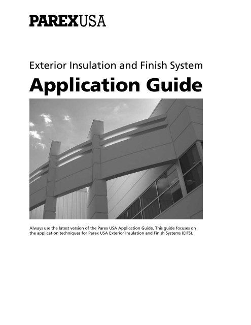
Exterior Insulation and Finish System<br />
<strong>Application</strong> <strong>Guide</strong><br />
Always use the latest version of the Parex USA <strong>Application</strong> <strong>Guide</strong>. This guide focuses on<br />
the application techniques for Parex USA Exterior Insulation and Finish Systems (EIFS).
INTRODUCTION: Exterior Insulation and Finish Systems (EIFS) have been used successfully<br />
for over 50 years in the US. It is an exterior wall cladding that is light weight, flexible,<br />
durable and adds energy saving insulation to the wall. The insulation can be shaped to<br />
easily provide architectural details. There are a vast choice of finish textures and colors<br />
available. The continuous reinforced lamina over the insulation makes this a face-sealed<br />
system. Standard EIFS do not require a weather or moisture-resistive barrier behind them<br />
because they are a facesealed cladding. Windows, doors and other objects do pass through<br />
the exterior wall. Proper flashing and sealants at those penetrations effectively protect the<br />
entire assembly from exterior water penetration. All the components of the EIFS are also<br />
user and environmentally friendly. All the liquid and paste materials are water-based. This<br />
chemistry provides a vapor permeable, breathable exterior that will allow incidental water<br />
in an exterior wall assembly to easily dry out.<br />
If a water-resistive barrier is requested by an architect or owner, or required by code behind<br />
a classic EIFS, Parex USA has several, tested, “Drainage” EIFS to choose from. One is designed<br />
for use with Light Commercial and Residential (LCR) construction that typically uses wood<br />
framing and sheathing. The other is designed for commercial construction that typically uses<br />
steel framing with a noncombustible gypsum or cement based sheathing. These Commerical<br />
Drainage EIFS are installed exactly the same as the Standard Systems. The difference is that<br />
the Commerical Drainage Systems require additional materials and application steps on the<br />
substrate and rough openings prior to the actual EIFS installation.<br />
This guide begins with a list of products that will be used for various segments of the<br />
three systems outlined. The second section of the guide covers General Installation<br />
Requirements. The third section describes the application of Standard EIFS from insulation<br />
board attachment through application of finish and sealants. The fourth section covers the<br />
treatment of the substrate and rough openings. The fifth section covers the substrate and<br />
rough opening treatments required for the Commercial Drainage EIFS.
EXTERIOR INSULATION AND FINISH SYSTEMS<br />
STANDARD EIF SYSTEM<br />
Adhesively attached, standard insulation board, using<br />
vertical ribbons of Parex USA basecoat & adhesive over an<br />
approved substrate.<br />
LIGHT COMMERCIAL/RESIDENTIAL (LCR)<br />
DRAINAGE EIFS<br />
Mechanically attached, standard flat insulation board with<br />
a water-resistive barrier incorporating in itself a means<br />
of drainage as a secondary weather barrier and drainage<br />
plane.<br />
OPTIONS:<br />
LCR - DM: Mechanically attached, standard flat<br />
insulation board with any code compliant<br />
water-resistive barrier and a drainage mat.<br />
LCR - GX: Mechanically attached, grooved insulation<br />
board with any code compliant waterresistive<br />
barrier.<br />
COMMERCIAL DRAINAGE EIFS<br />
Adhesively attached, standard flat insulation board,<br />
using vertical ribbons of adhesive bonded to Parex USA<br />
WeatherSeal installed over an approved substrate.<br />
OPTION:<br />
GX: Adhesively attached grooved insulation<br />
board bonded to Parex USA WeatherSeal<br />
installed over an approved substrate.
SYSTEMS AND PRODUCTS CROSS REFERENCE GUIDE<br />
STANDARD EIFS SYSTEMS<br />
Parex Standard / Optimum System<br />
TeifsFlex<br />
LaHabra Insul-Flex ® Standard System<br />
El Rey Insul-Flex ® Standard System<br />
MECHANICALLY FASTENED EIFS<br />
over a Water-Resistive Barrier<br />
Parex WaterMaster LCR / Optimum WaterMaster LCR<br />
TeifsPermadry<br />
LaHabra Insul-Flex WaterMaster LCR<br />
El Rey Insul-Flex WaterMaster LCR<br />
COMMERCIAL DRAINAGE EIFS<br />
on Parex USA WeatherSeal<br />
Parex Standard WaterMaster / Optimum WaterMaster System<br />
TeifsWeathertight VNT<br />
LaHabra Insul-Flex ® WaterMaster System<br />
El Rey Insul-Flex ® WaterMaster System<br />
PRODUCT TYPE<br />
Water-Resistive<br />
Barrier Coating<br />
Spray & Roll-On<br />
Trowel-On<br />
Vapor Retarder<br />
BRAND<br />
Parex Teifs LaHabra El Rey<br />
Parex USA WeatherSeal Spray & Roll-On<br />
Parex USA WeatherSeal Trowel-On<br />
Parex USA WeatherBlock<br />
Adhesive Only<br />
Non Cementitious<br />
303 Sheathing<br />
Adhesive<br />
Adheeze<br />
Sheathing Adhesive<br />
Cementitious-Acrylic<br />
121 (wet)<br />
121 Optimum Wet<br />
Teifs Base<br />
Teifs Base Optimum<br />
Insul-Bond Wet<br />
Basecoats &<br />
Adhesives<br />
Cementitious Dry Bag<br />
Non Cementitious<br />
121 Dry<br />
121 Optimum Dry<br />
121 HI<br />
121 Cool<br />
Quick Base in a Box<br />
ABC N -1<br />
TeifsBase DB<br />
Teifs Dry Base<br />
Optimum<br />
Quick Base in a Box<br />
TeifsStructure<br />
(Base only)<br />
Insul-Bond Dry<br />
Quick Base in a Box<br />
Insul-Bond P<br />
Quick Base in a Box<br />
Waterproof Basecoat<br />
Parex USA WeatherDry<br />
Primer<br />
Smooth<br />
Sanded<br />
Parex USA Primer<br />
Variance VariPrime Sanded<br />
Finishes<br />
Acrylic<br />
Dry<br />
Specialty<br />
Elastomeric<br />
Hydrophobic/Photocatalytic<br />
DPR Acrylic Finish DPR Acrylic Finish Perma-Finish Perma-Flex DPR<br />
DPR Optimum<br />
e-Lastic<br />
Ultra e-Lastic<br />
AquaSol<br />
TeifsFlex<br />
Parex USA Dry-Tex<br />
Parex USA Variance Finishes (excluding Aged Limestone)<br />
Teifs e-Lastic Perma-Lastic Perma-Flex Lastic<br />
* Parex USA products may be used with all brands
Table of Contents<br />
Products 1<br />
General Installation Requirements 3<br />
The <strong>Application</strong> of Standard System 4<br />
The <strong>Application</strong> of Mechancially Fastened EIFS System 18<br />
The <strong>Application</strong> of Commercial Drainage EIFS System 22
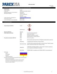
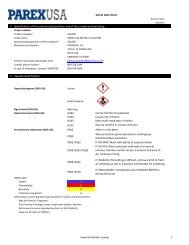
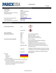
1. PRODUCTS<br />
Parex USA has developed a wide range of products<br />
to meet the physical and performance conditions of<br />
most projects. For a more detailed description of these<br />
products, please review our published Product Data<br />
Sheets and Safety Data Sheets (SDS).<br />
1<br />
Basecoats & Adhesives<br />
Cementitious<br />
Uses: As basecoats over EPS. As masonry levelers,<br />
adhesives for adhering EPS to masonry, exterior grade<br />
gypsum sheathing and glass mat gypsum sheathing.<br />
Cementitious-Acrylic Basecoat & Adhesive, pail products<br />
mixed with Type I or I-II Portland cement in a ratio of 1<br />
part Basecoat & Adhesive to 1 part cement by weight.<br />
Dry Basecoat & Adhesive, bag products, factory blended<br />
cementitious dry powder that only requires the addition<br />
of water.<br />
Waterproof Basecoat<br />
WeatherDry, pail product mixed with type I or I-II Portland<br />
cement in a ratio of 2 parts WeatherDry to 1 part cement<br />
by weight.<br />
Uses: Waterproof basecoat designed to protect sloped<br />
surfaces of rigid insulation boards.<br />
Non-Cementitious<br />
100% Acrylic Basecoat & Adhesive, are ready mixed 100%<br />
acrylic polymer based products. Do not mix this product<br />
with cement.<br />
Adhesives Only<br />
Sheathing Adhesive, pail product, adhesive for applying<br />
EPS to wood-based sheathings, exterior grade gypsum<br />
sheathing and glass mat gypsum sheathing.<br />
Parex USA Reinforcing Mesh<br />
352 Adhesive Mesh, 4.5 oz., fiberglass, self-adhesive<br />
mesh. Uses: For complex architectural details, not for use<br />
on full walls.<br />
355 Standard Mesh, 4.5 oz., alkali resistant glass fiber<br />
reinforcing mesh.<br />
Uses: Embedded into basecoat for typical<br />
application requirements.<br />
355.48 Long Standard, 4.5 oz., 48in., alkali resistant glass<br />
fiber reinforcing mesh.<br />
Uses: Embedded into basecoat for typical application<br />
requirements.<br />
356 Detail Mesh, 4.5 oz., highly flexible reinforcing mesh.<br />
Uses: For backwrapping and fabricating special shapes or<br />
contours, for double meshing corners.<br />
357 Corner Mesh, 7.2 oz., heavy duty, high tensile<br />
strength, mesh, specially folded.<br />
Uses: Embedded in basecoat for application at outside<br />
corners only.<br />
358.10 Intermediate Impact Mesh, 12 oz., high tensile<br />
strength, glass fiber reinforcing mesh.<br />
Uses: Embedded in primary layer of basecoat prior to<br />
additional mesh application to obtain medium impact<br />
level as defined by ASTM E2486.<br />
358.14 High Impact Mesh, 15 oz., high tensile strength<br />
glass fiber mesh.<br />
Uses: Embedded in primary layer of basecoat prior to<br />
additional 355 Standard Mesh application to obtain high<br />
impact protection as defined by ASTM E2486.
358.20 Ultra High Impact Mesh, 20 oz., ultra-high tensile<br />
strength glass fiber mesh.<br />
Uses: Embedded in primary layer of basecoat prior to<br />
additional 355 Standard Mesh application to obtain ultrahigh<br />
impact protection as defined by ASTM E2486.<br />
Primer<br />
Primer, provides a color base over cementitious basecoat<br />
prior to finish application. It improves the color consistency,<br />
trowelability and coverage of the finish. May be tinted.<br />
Sanded Primer, same as Primer, except it must be tinted to<br />
match and has a sand texture for improved application of<br />
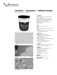
the finish. Required (undiluted) for Cerastone, Spraystone,<br />
and Tuffstone Granite applications.<br />
Finishes<br />
Acrylic Finish: 100% Acrylic co-polymer based, factory<br />
blended and integrally colored. They are applied over<br />
primed or unprimed basecoat to provide a durable,<br />
decorative wall coating.<br />
Cerastone, Spraystone, and Tuffstone Granite: Colored<br />
aggregate in a clear binder. Sanded Primer must be used<br />
under these finishes.<br />
Elastomeric Finish: 100% Acrylic-based elastomeric<br />
finishes. They are designed to go over new and existing<br />
stucco and concrete surfaces as well as either Stucco Level<br />
Coat or any EIFS Basecoat.<br />
Water-Resistive Barriers and Drainage Accessories<br />
StuccoWrap: Secondary barrier material with engineered<br />
drainage channels, used with Mechanically Fastened EIFS<br />
(WaterMaster LCR)<br />
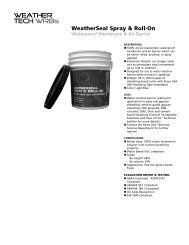
WeatherSeal Spray & Roll-On: 100% acrylic based, spray &<br />
roll-on water-resistive barrier membrane. Uses: Secondary<br />
water and air-resistive barrier in the Commercial Drainage<br />
EIFS system.<br />
WeatherSeal Trowel-On: 100% acrylic based, waterresistive<br />
barrier membrane. Uses: Secondary water and airresistive<br />
barrier in the Commercial Drainage EIFS system.<br />
WeatherBlock: A 100% Acrylic co-polymer fast drying<br />
vapor retarder, elastomeric waterproof and air barrier<br />
coating which can be either rolled, brushed, or spray<br />
applied.<br />
Uses: Secondary water and air resistive barrier in the<br />
Commmerical Drainage EIFS System<br />
396 Parex USA Sheathing Tape: Non-woven synthetic fiber<br />
tape to reinforce Parex USA WeatherSeal Spray & Roll-On<br />
at sheathing board joints and rough openings. 500 ft.<br />
(152m) lengths in either 4 in. (10cm), 6 in. (15cm), or 9 in.<br />
(23cm) widths.<br />
365 Flashing Membrane: Parex USA Flashing Membrane<br />
is a self-sealing polyester mat-faced, rubberized asphalt<br />
membrane that functions as a moisture and air barrier.<br />
It is 20 mils thick and grey in color. It can be applied to<br />
various substrates such as wood, metal, gypsum sheathing<br />
and to other water-resistive barriers. It functions as a seal<br />
and flashing at sills of rough openings, vented track and<br />
other similar conditions. It is available in two widths: 6 in.<br />
(152mm) and 12 in. (305mm) x 100 ft. (30.5m). Flashing<br />
Membrane Primer may be required for certain substrates.<br />
2<br />
369 DrainEdge: A perforated, spun bonded, polyolefin<br />
used at heads of system penetrations (windows, doors,<br />
etc.) to permit drainage without the use of track on<br />
noncombustible construction.<br />
OTHER MATERIALS AND TOOLS YOU WILL NEED<br />
Insulation Board: Ensure that the expanded polystyrene<br />
EPS insulation board used in the installation is listed for<br />
flame spread and smoke developed values, and conforms<br />
to ASTM C578 for Type I molded expanded polystyrene.<br />
Board should be aged a minimum of 6 weeks and be a<br />
maximum workable size of 2 ft. x 4 ft. (610mm x 119mm)<br />
with a minimum thickness of 1 in. (25.4mm) after rasping.<br />
To test the EPS board, break a small piece in half and<br />
immediately smell. The board should not be used if there<br />
is a noticeable solvent odor.<br />
Mechanical Fasteners: Attachment method for<br />
mechanically fastened EIFS Systems. Mechanical fasteners<br />
are not required for the Parex USA Standard System.<br />
However, they are sometimes specified for added security.<br />
In some cases mechanical fasteners may be used for<br />
renovation work or where adhesive cannot be used.<br />
Vented Track: Rigid exterior grade PVC plastic vented<br />
track designed to allow incidental moisture which<br />
may accumulate behind the system to exit. It may be<br />
used at foundation terminations in lieu of traditional<br />
backwrapping technique. Vented Track may not be used<br />
with Standard System or Commercial Drainage Systems<br />
except at foundation terminations, without approval<br />
from the Parex USA Technical Department.<br />
Portland Cement: Use type I or I-II, fresh and free of lumps.<br />
Water: Cool, clean potable water.<br />
Mixing Equipment: Use a 1/2 in. (13mm) chuck size power<br />
drill with a 6-8 amp motor capable of turning at 400-500<br />
rpm. The mixing paddle should be a steel dispersal mixer.<br />
Tools Common to the Plastering Trades. Including, but<br />
not limited to: a hawk, scoop, stainless steel trowels,<br />
plastic floats, rasping boards, margin trowels, corner<br />
trowels, groove tools and notched trowels for adhesive<br />
application.<br />
Other Tools: Utility knife, tape measure, paint rollers and<br />
tray (for primer), weight scale, extra buckets, electrical<br />
cords, EPS saw, drop cloths, masking tape, etc.<br />
PRODUCT STORAGE<br />
• Generally, store all Parex USA products in a clean, dry<br />
environment, protected from sunlight. Protect all<br />
pail goods from freezing. Freezing can cause product<br />
damage. See product data sheets for specific storage<br />
instructions.<br />
• Shelf Life: see product data sheets for specific shelf life<br />
information.<br />
• Store EPS and tracks flat. Standing on end could cause<br />
these materials to warp.<br />
• Store EPS away from sources of flame or high heat.<br />
Warning: EPS is combustible and can ignite and burn if<br />
exposed to fire of sufficient heat and intensity.<br />
• Store Parex USA reinforcing mesh in the shipping<br />
container in order to keep it clean and protected.
2. GENERAL INSTALLATION REQUIREMENTS<br />
These requirements are essential to good exterior<br />
insulation finish system (EIFS) practice. Failure to follow<br />
these requirements could lead to problems with the<br />
installation or ultimately, to system failure. Follow the<br />
requirements of the Product Data Sheets for each Parex<br />
USA product used.<br />
Environmental Requirements<br />
• Parex USA products should only be used when the air<br />
temperature in which they are applied is at 40ºF (4ºC) or<br />
higher during application and drying/curing.<br />
• Do not apply Parex USA products to substrates which<br />
have a surface temperature of 40ºF (4ºC) or lower.<br />
NOTE: Because Parex USA Basecoats & Adhesives, Finishes<br />
and Coatings are water based acrylic products, it is essential<br />
that the above requirements be followed. Humidity, wind,<br />
cold, heat, rain, etc., can all affect workability and drying<br />
of the coatings. As conditions warrant, tenting and/or<br />
tarping with supplemental heat might be necessary to<br />
maintain these requirements.<br />
The foam plastic insulation that is used in the Parex<br />
USA EIFS Systems is expanded polystyrene board, and<br />
the producers of the polystyrene boards recommend<br />
a maximum service temperature of 167ºF (75ºC). At<br />
temperatures higher than this value, the boards begin<br />
to deform. The use of dark color finishes over the<br />
polystyrene boards should be avoided in order to prevent<br />
the occurrence of high temperatures on the surface of the<br />
insulation boards. For more information see the Parex USA<br />
Technical Bulletin on using dark color finishes on EIFS.<br />
Substrate Requirements<br />
Verify that the substrate:<br />
• Is a type approved by Parex USA.<br />
• Is sound showing no signs of deterioration.<br />
• Is correctly applied and oriented to the framing.<br />
• Is correctly and tightly fastened.<br />
• Is free of any crumbling or looseness of surface.<br />
• Has no gaps or voids other than what is necessary for<br />
proper installation.<br />
• Has no projections or planar irregularities greater than<br />
1/4 in. (6mm) in a 4 ft. (1.2m) radius.<br />
• Is dry and is clean of any foreign materials such as<br />
oil, dust, dirt, form release agents, paints, wax, water,<br />
frost, etc.<br />
• Wood-based sheathings require a 1/8 in. (3mm) gap<br />
between adjacent panels.<br />
• Wood based sheathings require fastening in<br />
accordance with the building code or project<br />
specification if the specification exceeds the code.<br />
• Gypsum sheathings require fastening spaced not more<br />
than 8 in. (20cm) on center along framing members,<br />
and framing spaced not more than 16 in. (40cm) on<br />
center. For greater framing spacing, contact Parex<br />
USA Technical Services. Closer fastener spacing may be<br />
required by project specification or code.<br />
<strong>Application</strong> Coordination Requirements<br />
• Ensure that the installation of the system is being<br />
coordinated with other trades on the project.<br />
• Other trades are responsible for metal or plastic<br />
flashings as detailed by the design professional and<br />
must be installed properly along with other construction<br />
components such as windows and doors, louvers,<br />
doors,roof intersections, and deck headers.<br />
• Make sure details needed prior to application of EIFS are<br />
acceptable and in place.<br />
• Provide appropriate protection/covering for adjacent<br />
construction materials that are likely to be soiled by the<br />
application process.<br />
• Employ sufficient manpower to ensure a continuous<br />
coating application free of cold joints, scaffold staging<br />
shadows and texture variations.<br />
• Have scaffolding and other necessary equipment in<br />
place prior to the installation.<br />
• Have access to electricity for power tools.<br />
• Have access to cool, clean water of drinking quality<br />
at the area where system materials will be mixed.<br />
• Determine who will be responsible for installing<br />
the sealant.<br />
Before Beginning the Installation<br />
If there are any discrepancies with your initial inspection<br />
of the substrate, do not proceed with the application until<br />
all unsatisfactory conditions are corrected. The general<br />
contractor should be advised of all discrepancies so that<br />
appropriate action can be taken. Failure to advise the<br />
general contractor of unsatisfactory conditions before the<br />
application begins might be construed as acceptance, by<br />
the applicator, of the substrate for the purpose of installing<br />
the system. At this time, it may also be appropriate to once<br />
again review the contract documents to ensure that the<br />
installation will be consistent with what has been detailed<br />
and specified. Be sure to review critical detail areas of the<br />
project. It is certainly easier for all parties concerned if<br />
problems are addressed “up front” rather than when they<br />
present themselves in the installation process.<br />
Evaluate the installation - The following are some<br />
critical details:<br />
1. Window and door perimeters<br />
2. Tops of walls (roof line)<br />
3. Bottom of walls (grade or pavement)<br />
4. Penetrations (scuppers, fixtures, outlets, signage, etc.)<br />
5. Aesthetic features<br />
6. Expansion joints<br />
7. Abutments to Dissimilar Materials<br />
8. Gable Roof/Wall Intersection<br />
9. Flashing Locations<br />
10. Roofing<br />
11. Kick-out Flashing (flashing turn-outs)<br />
3
3. APPLICATION OF THE STANDARD SYSTEM<br />
The system should start 6 in. (15cm) above grade or 2<br />
in. (5cm) above the pavement. Substrates allowed are<br />
masonry, brick, stucco, exterior gypsum sheathing, glass<br />
mat gypsum, cement board, plywood and OSB sheathing.<br />
The system is qualified for application to certain types<br />
of OSB (oriented strand board) sheathing only in areas<br />
shown in the Parex USA Acceptable Substrates and Areas<br />
of Use Technical Bulletin.<br />
Backwrapping<br />
Backwrapping is the traditional method of encapsulating<br />
the insulation board edge. Backwrapping simply means<br />
that the insulation board edge is completely wrapped in<br />
mesh reinforced basecoat, and that the mesh continues in<br />
back of the insulation board edge.<br />
First determine the starting point on the wall. Then<br />
snap a straight, level chalk line. To begin backwrapping,<br />
install Parex USA 9-1/4 in. (23.5cm) wide 356 Detail Mesh<br />
lengthwise along chalk line so that a minimum of 2-1/2 in.<br />
(6.5cm) of the mesh will be behind the insulation board.<br />
The detail mesh can be installed by either using Parex<br />
USA Adhesives, or by attaching the mesh onto sheathing<br />
substrates with corrosion resistant staples or nails in a<br />
length that does not penetrate through the sheathing.<br />
If Parex USA Adhesive is used to attach the mesh to the<br />
substrate, special care should be taken to ensure that the<br />
exposed ends of the backwrapping mesh do not become<br />
covered with adhesive materials. (Fig 4.1) Adhesive on<br />
the exposed ends will prevent proper embedding of the<br />
mesh at the board edge and face when the backwrapping<br />
procedure is completed later.<br />
Track is used at foundation terminations as an alternative<br />
to backwrapping and other locations on combustible<br />
construction only. Although it cannot be used in every<br />
situation, it provides a factory formed termination. Track<br />
also provides an excellent substrate for sealant bonding.<br />
Track may not be used on Standard Systems or Commerical<br />
Drainage Systems except at foundation terminations.<br />
For special exceptions, contact the Parex USA Technical<br />
Department.<br />
Fig 4.1<br />
4
INSTALLING THE INSULATION BOARD<br />
Choosing the Right Adhesive<br />
After the preliminary task of backwrapping or fastening<br />
track has been accomplished, you are now ready to adhere<br />
the EPS insulation board to the substrate. The adhesive<br />
should be selected depending upon the substrate. Table 5.1<br />
below is a guide for matching adhesives with substrates.<br />
Table 5.1: ATTACHMENT BY SUBSTRATE<br />
Masonry Type<br />
Substrates<br />
(unpainted)<br />
Sheathed Substrates<br />
(unpainted)<br />
Substrates coated with<br />
Parex USA WeatherSeal<br />
or WeatherBlock<br />
Expanded Metal Lath<br />
SUBSTRATES<br />
CMU<br />
Poured in place & Pre-Cast Concrete<br />
Brick<br />
Exterior Gypsum Sheathing<br />
Glass Mat Gypsum Sheathing<br />
Cement Board<br />
Metal Siding<br />
Wood Sheathing<br />
Exterior Gypsum Sheathing, Glass Mat<br />
Gypsum Sheathing, Cement Board,<br />
Wood Sheathing, Masonry, Brick<br />
Nominal 3.4 lb./sq. yd., flat,<br />
galvanized G 60 or greater<br />
ADHESIVE<br />
any Cementitious Adhesive<br />
any Cementitious Adhesive<br />
any Cementitious Adhesive<br />
any Cementitious Adhesive, 100% Acrylic, Sheathing Adhesive<br />
any Cementitious, 100% Acrylic, Sheathing Adhesive<br />
any Cementitious Adhesive<br />
100% Acrylic Basecoat & Adhesive, Sheathing Adhesive and M.F.**<br />
100% Acrylic Basecoat & Adhesive, Sheathing Adhesive<br />
Any Adhesive<br />
any Cementitious Adhesive<br />
**M.F. Mechanical Fasteners - please contact Parex USA Technical Services.<br />
Starting and Stopping the System<br />
At all system terminations, install 356 Detail Mesh for<br />
back-wrapping. When using 356 Detail Mesh, be sure<br />
to backwrap the mesh at least 2-1/2 in. (6cm) behind<br />
insulation board.<br />
Applying EPS Insulation Board to Sheathing Substrates<br />
On sheathing applications, the first course of insulation<br />
board usually must be halved in width to allow for a<br />
minimum 1 in. transition beyond the sill plate and the<br />
12 in. (30cm) offset of the horizontal insulation and<br />
sheathing board joints (Fig 5.1). The offset of the vertical<br />
insulation and sheathing board joints typically should be<br />
no less than 8 in. (20cm). Remember, at no time should the<br />
vertical or horizontal joints in the sheathing line up with<br />
the insulation board joints. On masonry substrates these<br />
requirements do not apply.<br />
Fig 5.1<br />
5
Applying EPS Insulation to Masonry Substrates<br />
EPS board must not bridge expansion joints in masonry or<br />
concrete substrates. Instead, an expansion sealant joint is<br />
created in the EIF System over the substrate joints.<br />
Adhesive <strong>Application</strong> Trowels<br />
Sheathing Adhesive requires that these trowels be used<br />
with these products for optimum adhesive performance<br />
and coverages:<br />
Trowel Size:<br />
Minimum 5/8 in. (16mm) U-notched trowel for masonry,<br />
concrete and metal lath substrates with any Cementitious<br />
Basecoat & Adhesive (Fig 5.2).<br />
1/2 in. (12mm) notched trowel for WaterMaster EIFS with<br />
any Cementitious Basecoat & Adhesive (Fig 5.3).<br />
3/16 in. (5mm) U-notched trowel for sheathing substrates<br />
with Sheathing Adhesive (Fig 5.4).<br />
Minimum 5/16 in. (8 mm) notched trowel for sheathing<br />
substrates with any 121 Basecoat & Adhesive (Fig 5.5).<br />
3<br />
Fig 5.2<br />
Fig 5.3<br />
Fig 5.4<br />
Applying Adhesive to the Back of the EPS Insulation Board<br />
The first step is to ensure that the adhesive is compatible<br />
with the substrate. Using the correct sized notched trowel,<br />
the adhesive can now be applied to the insulation board.<br />
Apply the adhesive to the back-facing side of the insulation<br />
board so that when it is applied to the substrate, the<br />
notched trowel pattern runs consistently (Fig 5.6).<br />
The notched pattern should cover the entire board from<br />
edge to edge. To ensure sufficient bonding and coverages<br />
of the adhesive, EPS board should be visible in between the<br />
notches of adhesive. Adhesive should only be applied to<br />
the back-facing side of the insulation board. Remove any<br />
adhesive from EPS board edges. Adhesive between board<br />
edges can cause cracking.<br />
5<br />
16 ” 3<br />
4 ”<br />
5 ” 16<br />
5/16” NOTCHED TROWEL PROFILE<br />
Fig 5.5<br />
Installing the Insulation Board<br />
Prior to installing the insulation board it is important<br />
to assess all terminations of the system and ensure that<br />
backwrapping, edge wrapping, track or seal tape is used in<br />
these locations.<br />
Slide and push the insulation boards into place on the<br />
wall using caution not to dent or damage the board.<br />
Insert insulation board (Fig 5.7) edges all the way into<br />
track or backwrap. Apply firm, even pressure to the entire<br />
insulation board once it is in place. A rasping board is a<br />
useful tool to press with even pressure without damaging<br />
the insulation board. Install the insulation board in<br />
a running bond pattern, staggering vertical joints in<br />
successive courses. Best practice would be no less than 8 in.<br />
(20cm) from the adjacent insulation board joints.<br />
Abut boards tightly at joints to produce a flush,<br />
continuously even surface with minimum gaps (Fig 5.8).<br />
Scrape excess adhesive off the edges of the boards (Fig<br />
5.9).<br />
6<br />
Fig 5.6<br />
Fig 5.7
Fig 5.8<br />
Fig 5.9<br />
Fill any gaps larger than 3/32 in. (2mm) with slivers<br />
of insulation board (Fig 5.10) or a Low Expanding<br />
Polyurethane Spray Foam approved for use with EIFS.<br />
Adhesive should not be applied to the slivers. Continue<br />
installing the EPS boards horizontally, staggering the<br />
boards and overlapping the substrate joints. Filling gaps<br />
with adhesive/basecoat will result in cracks in the lamina.<br />
Fig 5.10<br />
Offset insulation board joints 8 in. (20cm) or more from<br />
the corners of openings around doors, windows or other<br />
similar conditions (Fig 5.11). Plan the work so that the<br />
insulation board around the corner is cut in an “L” shape<br />
from a single piece (Fig 5.12). Insulation board joints<br />
should never align with opening corners.<br />
Leave a uniform 1/2 in. space between the edge of the EPS<br />
and the window, door, etc. when the system is terminated<br />
by backwrapping, so that backer rod and sealant can be<br />
installed later.<br />
Fig 5.11<br />
Fig 5.12<br />
At all outside and inside corners always interlock or<br />
stagger the insulation board joints, board joints on the<br />
opposite end should be no less than 8 in. (20cm) from the<br />
corner (Fig 5.13). Plumb all outside corners by snapping a<br />
chalk line. Level the EPS board to the chalk line by rasping.<br />
Maintain a minimum thickness of 3/4 in. (19mm) of EPS.<br />
Remove all loose EPS particles from the wall surface.<br />
Fig 5.13<br />
7
PREPARING FOR THE BASECOAT APPLICATION<br />
The adhesive must dry so that EPS board is secure on the<br />
wall before proceeding. Adhesive must dry in accordance<br />
with the product data sheet. Drying time may be shortened<br />
with Parex USA Accel-Pak. In cool or damp weather, the<br />
adhesive may require longer to drying time.<br />
Leveling the EPS<br />
True wall surfaces by leveling EPS. Do not build up<br />
basecoat thickness to true walls. Level the entire surface of<br />
the EPS board with either a rasping board or power rasper<br />
(Fig 6.1).<br />
Fig 6.1<br />
Check the surface with a straight edge for high spots,<br />
leveling as necessary (Fig 6.2). Maintain a minimum<br />
thickness of 3/4 in. (19mm) of EPS. Thoroughly remove<br />
loose EPS particles from the surface of the insulation<br />
board.<br />
Aesthetic Grooves or Reveals<br />
Establish the locations of all aesthetic grooves or reveals,<br />
bands or other projections with a chalk line. The aesthetic<br />
grooves should not line up with the EPS board joints.<br />
Aesthetic grooves or reveals can generally be cut with a<br />
router or hot knife. A minimum thickness of 3/4 in. (19mm)<br />
of insulation board must be maintained in back of the<br />
groove (Fig 6.3). The bottom surface of any horizontal<br />
groove must be sloped min. 1 in 2 pitch.<br />
3/4”<br />
Fig 6.2<br />
Fig 6.3<br />
Attaching EPS Aesthetic Trim<br />
The following Parex USA adhesives can be used to attach<br />
foam to foam: any Cementitious Basecoat & Adhesive.<br />
Small EPS aesthetic trim not more than 3 in. (7.6cm) thick<br />
by 12 in. (30cm) wide can now be laminated over installed<br />
insulation board (Fig 6.4), not exceeding the grand total<br />
thickness as allowed by the system specifier. Using either<br />
a 5/16 in. (8mm) or 1/2 in. (13mm) notched trowel, apply<br />
Parex USA Adhesive to the back of the trim feature, as<br />
described earlier. Attach the trim piece to the face of the<br />
insulation board with firm and even pressure. In some cases<br />
it may be necessary to temporarily pin the trim into place<br />
with nails to give the adhesive time to set up. Remove<br />
temporary pinning after the adhesive has dried.<br />
Fig 6.4<br />
8
Larger EPS aesthetic trim should be attached directly to<br />
the substrate (Fig 6.5). Using the appropriate notched<br />
trowel for the adhesive specified, apply adhesive to the<br />
back-face of the trim feature as described earlier. Attach<br />
the trim piece directly to the substrate with firm and<br />
even pressure. If necessary, corrosion-resistant mechanical<br />
fasteners may be used in conjunction with the appropriate<br />
Parex USA Adhesive to affix the feature temporarily or<br />
permanently (Please contact Parex USA Technical Services<br />
for recommendations). Allow the adhesive to fully dry a<br />
minimum of 24 hours, or longer depending on conditions,<br />
before rasping and basecoating aesthetic trim features.<br />
NOTE: The slope on the aesthetic foam trim features,<br />
bands, cornices and window sills needs to have a 6/12<br />
slope.<br />
Fig 6.5<br />
Fig 6.6<br />
Backwrapping Mesh<br />
Check that EPS has all been leveled before proceeding. At<br />
this time, all terminations to be backwrapped should have<br />
free-hanging detail mesh in place (Fig 6.6). To continue the<br />
backwrapping procedure, trowel the specified basecoat<br />
onto the exposed insulation board edge and face in an<br />
area wide enough to embed the width of backwrapped<br />
mesh. Embed the mesh into the fresh basecoat with a<br />
stainless steel trowel. Corner trowels should be used to<br />
properly embed the returns.<br />
Meshing Corners<br />
The inside corners should be double-wrapped with<br />
reinforcing mesh. This can be done using one of two<br />
different methods:<br />
(1) Apply a primary layer of basecoat wide enough to<br />
accommodate Parex USA 356 Short Detail Mesh. Embed the<br />
mesh into the fresh basecoat, then apply the 355 Standard<br />
Mesh around the corner so there is a double layer of mesh<br />
(Fig 6.7).<br />
Fig 6.7<br />
Fig 6.8<br />
(2) Another way to double mesh corners is to wrap and<br />
embed mesh in basecoat around the corner from one side<br />
to the other side. Next duplicate this process coming from<br />
the other side. The double mesh should extend at least 8<br />
in. (20cm) from the corner in both directions. (Fig 6.8).<br />
Outside corners can be meshed in a similar manner. For<br />
greater strength and a sharper line, use Parex USA 357<br />
Corner Reinforcing Mesh. This heavy duty reinforcing mesh<br />
is easily folded for ease of application. Standard mesh is<br />
then lapped over the corner mesh and extends at least 8 in.<br />
(20cm) from the building corner.<br />
A corner trowel should be used to smooth out the corner<br />
at its edge, forming a clean, straight line. If necessary,<br />
apply additional basecoat materials to ensure that<br />
the mesh is not visible. A slight pattern of the mesh is<br />
acceptable, due to shrinkage of the cementitious basecoat<br />
upon drying.<br />
9
Meshing Aesthetic Grooves or Reveals<br />
The mesh-reinforced basecoat must be continuous through<br />
these recessed features. To mesh the groove or reveal,<br />
apply a primary layer of basecoat into the groove and over<br />
an area wide enough to embed the width of the detail<br />
mesh on either side (Fig 6.9).<br />
Begin embedding the Parex USA 356 Detail Mesh into the<br />
groove using a tool fabricated in the profile of the feature<br />
(Fig 6.10). Do not cut the mesh during this process.<br />
Fig 6.9<br />
With a trowel, finish embedding the detail mesh on the<br />
sides of the groove (Fig 6.11). If the mesh is still visible,<br />
apply additional basecoat. A slight pattern of the mesh is<br />
acceptable, due to shrinkage of the cementitious basecoat<br />
upon drying.<br />
Meshing Aesthetic Trim<br />
As a general rule, adhesives used in attaching aesthetic<br />
trim should be allowed to dry a minimum of 24 hours<br />
or longer, depending on conditions, before applying<br />
basecoat.<br />
Aesthetic trim features are prepared with a basecoat<br />
similar to the rest of the wall system. Basecoat and<br />
embedded mesh should not only be applied to the feature,<br />
but should also lap not less than 2-1/2 in. (6.5cm) onto<br />
the adjacent wall plane. Completely embed mesh in the<br />
fresh basecoat. Apply additional basecoat as necessary to<br />
completely cover the mesh.<br />
Like aesthetic grooves and reveals, the area adjacent to<br />
the feature is overlapped with mesh reinforced basecoat<br />
during the standard application procedure.<br />
Fig 6.10<br />
Fig 6.11<br />
Butterfly Reinforcements<br />
Apply “butterfly” corner reinforcing mesh diagonally<br />
at the corners of all openings such as doors, windows,<br />
recessed features, etc. Butterfly mesh is cut from 356<br />
Detail Mesh to a length of 12 in. (30cm). Apply butterfly<br />
mesh at corners of bands around openings (Fig 6.12). The<br />
dimensions of the butterfly mesh may be reduced to fit the<br />
bands. The continuous wall mesh is applied either under or<br />
over butterfly mesh.<br />
Fig 6.12<br />
10
Fig 7.1<br />
APPLYING BASECOATS<br />
To begin this step, cut reinforcing mesh to workable<br />
lengths.<br />
Standard Mesh and Basecoat <strong>Application</strong> Procedure<br />
All Parex USA Basecoats are applied to the face of the<br />
insulation board in the same manner. Using a stainless steel<br />
trowel, apply an even layer of basecoat approximately 1/16<br />
in. to 3/32 in. (1.6mm to 2mm) thick onto the surface of the<br />
insulation board in an area slightly larger than the 38 in.<br />
(1m) width of the reinforcing mesh.<br />
Immediately embed the reinforcing mesh into the fresh<br />
basecoat, trowelling it from the center and outward to its<br />
edges, cutting off any accumulated excess basecoat (Fig 7.1).<br />
Fig 7.2<br />
This method keeps the mesh laying flat, ensuring<br />
consistent embedment into the basecoat (Figure 7.2).<br />
Additional basecoat material may be added to the<br />
surface of the fresh basecoat in order to ensure proper<br />
embedment of the mesh.<br />
After drying the color of the reinforcing mesh should<br />
not be visible at the surface of the Basecoat & Adhesive<br />
material. A slight pattern of the mesh is acceptable due to<br />
shrinkage of the cementitious basecoat upon drying. In the<br />
event that any a portion of the mesh is still visible after the<br />
basecoat materials has dried, apply a second skim coat to<br />
those areas.<br />
The installation progresses by applying basecoat similarly<br />
in areas adjacent to the previous application. Take care to<br />
overlap reinforcing mesh a minimum of 2-1/2 in. (6.5cm) at<br />
all meeting ends and edges as the application progresses.<br />
To avoid a buildup of basecoat that could be noticeable in<br />
the finished application, mesh end overlaps can be held<br />
8 in. (20cm) or more from corners.<br />
Final Appearance of Basecoat <strong>Application</strong><br />
The basecoat application should be smooth, approximately<br />
1/16 in. (1.6mm) thick, and free of trowel lines with<br />
no visible color signs of the reinforcing mesh. Allow a<br />
minimum drying time of 24 hours (or in accordance with<br />
Product Data Sheet) or longer depending on conditions,<br />
before applying additional Parex USA coatings. Drying time<br />
may be shortened with Parex USA Accel-Pak. This allows<br />
the basecoat to form a positive bond.<br />
11
IMPACT MESH APPLICATION<br />
In areas requiring heavy duty impact protection, Parex USA<br />
offers two options: 358.20 Ultra High Impact Mesh, which<br />
is 20 oz. mesh, and 358.14 High Impact Mesh which is 15<br />
oz. mesh. Requirements are generally outlined in the job’s<br />
specification and are shown on the drawings.<br />
At areas specified for impact protection, apply<br />
Parex USA basecoat approximately 3/32 in. (2mm) thick to<br />
the insulation board. Immediately embed Parex USA heavy<br />
duty mesh into the wet basecoat.<br />
Edges and ends of heavy duty mesh must tightly abut one<br />
another. Do not overlap heavy duty mesh.<br />
Either allow the basecoat embedding the heavy duty mesh<br />
to dry completely or immediately embed standard mesh<br />
over it. Unless standard mesh is immediately applied,<br />
cover heavy duty mesh completely with basecoat, allow<br />
a minimum of 24 hours to pass, or longer depending<br />
on conditions, prior to applying additional Parex USA<br />
coatings. This allows the first layer of basecoat to form a<br />
positive bond.<br />
Examine the hardened first layer of basecoat for<br />
projections of loose strands of reinforcing mesh. Correct as<br />
necessary to produce a flat working surface.<br />
The next step is to apply a second layer of basecoat and to<br />
embed Parex USA 355 Standard Mesh.<br />
The 355 Standard Mesh joints must be offset a minimum<br />
of 6 in. (15cm) from the joints of the previously installed<br />
heavy duty mesh. Standard and heavy duty mesh ends and<br />
edges should never align.<br />
Intermediate Impact Resistance<br />
For intermediate impact resistance, Parex USA 358.10<br />
Intermediate Impact Mesh is applied in the same manner as<br />
high impact applications, followed by an application of 355<br />
Standard Mesh embedded in basecoat.<br />
As an alternative, when specified, Parex USA 358.10<br />
Intermediate Impact Mesh can be embedded into wet<br />
basecoat with edges and ends tightly abutted. Immediately<br />
following this procedure, Parex USA 356 Short Detail Mesh<br />
strips are centered over the butted ends and edges of the<br />
358.10 Intermediate Reinforcing Mesh. Additional basecoat<br />
is applied to feather out the mesh joints and to completely<br />
embed the mesh to produce a flat, uniform surface.<br />
Intermediate mesh may also be overlapped a minimum of<br />
2-1/2 inches, however care must be taken to avoid a bump<br />
in the basecoat at this termination and the basecoat must<br />
be feathered onto either side.<br />
12
FINISH APPLICATION<br />
Before the application of the finish, the basecoat must<br />
be dry and have cured a minimum of 24 hours or longer<br />
as required by conditions or in accordance with the<br />
product data sheet. Examine the cured basecoat for any<br />
irregularities. Correct these irregularities to produce<br />
a flat surface. Review environmental and application<br />
coordination sections of the General Requirements. Work<br />
on the shaded side of the building whenever possible.<br />
Primer or Sanded Primer<br />
Primer is optional, except if specified, when applying<br />
finishes to cementitious basecoats. Primer is applied to<br />
minimize cementitious basecoat water absorption and<br />
the risk of efflorescence, and to provide consistent color<br />
under the finish. It also eases the trowelability floating<br />
characteristics of the finish, and will improve the coverage<br />
of the finish.<br />
• Parex USA Variance VariPrime Sanded is required for<br />
Cerastone, Spraystone and Tuffstone Granite Finishes.<br />
Fig 9.1<br />
• The Parex USA Sand Smooth Finish cannot generally<br />
be floated. Texture will be “as-trowelled”. For the<br />
smoothest application, apply in two tight coats. Allow<br />
first coat to dry enough that it will not be disturbed<br />
during application of the second coat. When second<br />
coat is partially dry, trowel to desired smoothness.<br />
Light, consistent misting with water during smoothing<br />
will increase smoothness. Variations in color tint and<br />
smoothness should be expected.<br />
Mixing and Applying Primer<br />
Mix the primer thoroughly with the appropriate mixer and<br />
adjust consistency with up to 2 gal (3.8 L) of cool, clean<br />
potable water for ease of application. Apply the primer<br />
by either rolling or spraying with suitable equipment in<br />
a continuous coat (Figs 9.1). The primer does not have to<br />
look like a professional paint job, but it should cover the<br />
basecoat. When cutting-in with a brush around edges of<br />
the system do not allow a buildup of primer. If a buildup is<br />
present it will produce a visible and unsightly difference in<br />
the finish applied over it.<br />
Cerastone, Spraystone and Tuffstone Granite finishes:<br />
Sanded Primer is required and must be uniform, with no<br />
variation in appearance from basecoat showing through.<br />
Sanded Primer must be specifically tinted for Cerastone,<br />
Spraystone and Tuffstone Granite colors.<br />
Parex USA Finishes<br />
Parex USA offers a variety of different finishes in a<br />
wide range of colors that can accommodate a variety of<br />
texturing techniques. Each finish is acrylic polymer based,<br />
pre-mixed, and tinted for the requirements of any project.<br />
• Swirl Finishes are applied with a stainless steel trowel<br />
and textured with a hard plastic float.<br />
• Parex USA Variable Texture Finish is a high-build<br />
product that can be applied using various application<br />
techniques.<br />
• Parex USA Sand Finishes are applied using a stainless<br />
steel trowel and textured with a stainless steel trowel or<br />
a plastic float.<br />
• The Sand Fine Finish is less forgiving on irregular<br />
substrates. Use extra care on the basecoat to control<br />
consistency of the texture.<br />
• Using the appropriate spray equipment and techniques,<br />
all Parex USA acrylic finishes can be sprayed to achieve a<br />
wide variety of textures.<br />
13
Mixing Parex USA Acrylic Finishes<br />
Stir to obtain a homogenous consistency using a heavy<br />
duty 1/2 in. (13mm) drill with a rust free mixer at 400-500<br />
RPM (Fig 9.2). Avoid air entrapment.<br />
To adjust workability, small amounts of cool, clean, potable<br />
water may be added as necessary. Do not exceed the<br />
amount of water recommended on the product data sheet.<br />
If water is added be sure that the same amount is added to<br />
each subsequent pail used. This ensures color and texture<br />
consistency.<br />
Fig 9.2<br />
Use single batch numbers of finish within a wall area<br />
defined by corners. Batch numbers are marked on the pail.<br />
If changing batches within a wall is unavoidable, then<br />
intermix batches to ensure consistent product. (Fig 9.3).<br />
Fig 9.3<br />
Assessing the Finish <strong>Application</strong><br />
In assessing the finish application, keep in mind that the<br />
material must be applied continuously for best results.<br />
When possible, plan the day’s work to best take advantage<br />
of terminations in the wall plane. For example: work<br />
between columns, aesthetic joints, expansion joints,<br />
corners, etc. For larger areas sufficient manpower must be<br />
assembled to ensure an application free of cold joints and<br />
staging lines (Fig 9.4).<br />
Direct sunlight, wind, temperature and humidity can all<br />
have an effect on the workability and drying time of Parex<br />
USA finishes. When possible, work the shady side of the<br />
building or tarp the scaffolding.<br />
Fundamentals of Successfully Applying Finish<br />
• Get samples approved and signed by the customer<br />
before the finish is made.<br />
• Box finish from different batches.<br />
• Run one batch of finish from corner to corner.<br />
• Avoid application in direct sunlight.<br />
• Always work to a wet edge.<br />
• Have sufficient manpower to work a job.<br />
• Stop work at a termination point.<br />
Fig 9.4<br />
14
Applying Parex USA Finishes<br />
Use the same tools and techniques to apply and texture the<br />
finish as used for the approved samples.<br />
Apply Parex USA finishes with a clean stainless steel trowel<br />
(Fig 9.5). The thickness of the finish application should<br />
equal the size of the product’s aggregate. Variable Texture<br />
Finish can be applied up to 1/4 in. (6mm) thick at thickest<br />
part of a texture pattern, but its average thickness is<br />
limited to 1/8 in. (3mm) maximum.<br />
Fig 9.5<br />
Do not apply finishes on or in areas to receive sealant.<br />
To ensure that the application remains consistent, a<br />
“wet edge” must be maintained at all times between<br />
termination breaks in the wall area (Fig 9.6).<br />
Fig 9.6<br />
Fig 9.7<br />
Texturing Finish<br />
Parex USA Swirl Finishes can be textured using a hard plastic<br />
float in a uniform circular or figure eight motion (Fig 9.7). To<br />
ensure consistency in the application, all applicators should<br />
use the same type of tool and motion to float.<br />
During texturing, frequently remove any buildup of finish<br />
on the plastic float. For best results, two passes with the<br />
plastic float are recommended. Warning: Do not allow<br />
water on the float or wall while texturing. The additional<br />
water from the float may result in a visible color difference<br />
when the finish application has dried.<br />
Parex USA Variable Texture Finish can be applied and<br />
textured much like other plaster type materials. Using<br />
traditional plastering methods use Variable Texture to<br />
create skip trowel or stipple effects. Remember: Variable<br />
Finish should not exceed 1/4 in. (6mm) at its thickest point<br />
and should average no more than 1/8 in. (3mm) thick.<br />
Parex USA Sand Finishes are used to achieve a relatively<br />
uniform texture. Apply, then texture these finishes with a<br />
stainless steel trowel or hard plastic float using the same<br />
guidelines mentioned for Swirl Finishes. See the Product<br />
Data Sheet for more information.<br />
15
PROTECTING THE SYSTEM AFTER INSTALLATION<br />
• Plan and have ready for immediate use any protective<br />
measures required.<br />
• Immediately after installation protect the Parex USA<br />
System from weather and other damage until all<br />
sealants and flashings have been installed.<br />
• After each application of the basecoat & adhesives and<br />
finishes, the ambient air temperature must remain at<br />
40ºF (4ºC) or higher for a minimum of 24 hours, or until<br />
the coatings are completely dry, which may take several<br />
days in high humidity and/or cool weather.<br />
Although it may not be outwardly apparent, freshly<br />
applied coatings that seem hard and dry on the surface<br />
often require protective measures to ensure their proper<br />
cure through their entire thickness. Take protective<br />
measures, especially if freezing temperatures, rain, snow or<br />
other damaging weather conditions are likely.<br />
Temperatures below 40ºF (4ºC) can slow down or stop the<br />
film formation of the acrylic polymers. Damage from cold<br />
conditions often remains undetectable in the short term,<br />
but shows up much later as the coatings crack, become<br />
crumbly, or delaminate.<br />
Like excessive cold, precipitation can affect the proper<br />
curing of coatings, but its results can be dramatically fast. A<br />
sudden downpour can wash fresh uncured coatings directly<br />
off a wall.<br />
As circumstances may dictate, work according to the<br />
weather or provide appropriate sheltering, such as tenting<br />
and/or tarping. To maintain proper curing temperature,<br />
supplemental means of heating the temporary shelter may<br />
have to be used.<br />
Flashings and Sealants<br />
EIF systems, like other weather-protective wall materials,<br />
rely on flashings and sealants to prevent moisture entry<br />
behind the materials. Moisture behind the system can<br />
lead to damage to the interior of the wall. On moisture<br />
sensitive substrates, moisture can cause delamination of<br />
the system or loss of substrate attachment.<br />
16
Fig 10.1<br />
More About Sealants<br />
Sealants, provide two vital functions:<br />
1. They effectively seal joints between abutting<br />
materials against the weather; and<br />
2. They absorb thermal expansion and contraction. In<br />
general, sealant joints are constructed similar to Fig<br />
10.1. Parex USA requires the surface of the system<br />
which will receive the sealant to be either meshreinforced<br />
basecoat or track. Do not return finish<br />
into the joints or other areas to receive sealant.<br />
Sealants are applied in strict conformance with the<br />
sealant manufacturer’s recommendation.<br />
Because of the wide variety of surface materials and<br />
conditions, check with the sealant manufacturer to ensure<br />
compatibility of the sealants to the surface(s) to which<br />
they will be applied. Special surface preparation or primers<br />
may be necessary. NOTE: Parex USA Basecoats and Finishes<br />
must be thoroughly dry before sealants can be applied.<br />
Parex USA Cementitious Basecoats require a minimum<br />
drying time of three days and longer during conditions<br />
of cool temperatures or high humidity; Parex USA 100%<br />
Acrylic Basecoat and Finishes may require further drying<br />
time.<br />
17
4. STEPS FOR MECHANICALLY FASTENED EIFS<br />
FOR LIGHT COMMERCIAL AND RESIDENTIAL<br />
CONSTRUCTION<br />
NOTE: All WaterMaster LCR systems require waterproofing of<br />
all openings prior to system application and 1-1/2 in. (38mm)<br />
minimum EPS thickness.<br />
INSTALLING VENTED TRACK<br />
Vented track provides a means for incidental moisture to<br />
escape at the bottom of the system. Install vented track<br />
along a level or plumb base line approximately 6 in. (152mm)<br />
above grade or 2 in. (51mm) above pavement. Install above<br />
flashings and at expansion joints. Attach the track to the<br />
substrate at 10-12 in. (254-305mm) intervals along its length<br />
and insert splices at all track joints. On Mechanically Fastened<br />
EIFS installation of the Water-Resistive Barrier must lap into<br />
the track.<br />
On sheathing substrates, fasten the track through the<br />
sheathing and into the framing. Use corrosion resistant<br />
screws, nails or masonry anchors as appropriate for the<br />
substrate. Bottom of vented track shall be not less than 1 in.<br />
(25mm) below bottom of wall framing (Fig 11.1).<br />
At this point in the construction, sheathing must be on<br />
the building. WINDOWS AND DOORS MUST NOT BE IN<br />
PLACE. Vented track should be installed at the bottom<br />
termination point.<br />
The next step is to properly wrap all rough openings with<br />
Parex USA Flashing Membrane or StuccoWrap¨ FlexWrap<br />
or Reinforced Parex USA WeatherSeal. Closely follow the<br />
instructions below:<br />
Parex USA recommends an adhesion test of the Flashing<br />
Membrane on the substrates. If adhesion to substrate is<br />
found to be marginal, a primer shall be used to ensure<br />
optimal adhesion. Metal surfaces may need to be<br />
solvent wiped or abraded to achieve good adhesion. The<br />
recommended primers used with 365 Flashing Membrane<br />
are the Protecto Wrap No. 6000 Water-Based Primer or the<br />
Protecto-Tak Spray Adhesive.<br />
1. Installing the Corrugated Water-Resistive Barrier Under<br />
the Sill: Cut to 12 in. (305mm) and approximately 2 in.<br />
(610mm) wider than window and staple into place at<br />
the bottom of the rough opening (Fig 11.2).<br />
2. Installing Membrane “Bandages”: Cut “bandages” to<br />
4 in. (102mm) x 6 in. (152mm). Peel protective backer<br />
from the membrane and install diagonally at sill corners<br />
as shown. Sheathing or Corrugated Water-Resistive<br />
Barrier should not be visible at the corners of the rough<br />
opening (Fig 11.3). This step can be skipped if a “T” strip<br />
of Parex USA 365 Flashing Membrane is applied in the<br />
corner and over the Corrugated Water-Resistive Barrier.<br />
3. Cutting Flashing Membrane: Cut a piece of 365 Flashing<br />
Membrane 8 in. (203mm) longer than the rough<br />
opening width. Make two small cuts 2 in. (51mm) long<br />
through the membrane.<br />
4. Folding Flashing Membrane: Fold membrane to<br />
conform with rough opening. Peel protective backer<br />
from membrane to expose adhesive (Fig 11.5).<br />
5. Installing the Flashing Membrane: Install the “self<br />
sticking” membrane at the rough opening. Membrane<br />
should lap over the previously installed “bandages”<br />
and Corrugated Water-Resistive Barrier (Fig 11.6).<br />
______________________________________________ Fig. 11.1<br />
______________________________________________ Fig. 11.2<br />
______________________________________________ Fig. 11.3<br />
______________________________________________ Fig. 11.4<br />
______________________________________________ Fig. 11.5<br />
______________________________________________ Fig. 11.6<br />
18
6. Cutting Water-Resistive Barrier for Jambs: Cut Water-<br />
Resistive Barrier to fit rough opening jamb (Fig 11.7).<br />
Fig. 11.7 ______________________________________________<br />
7. Installing Water-Resistive Barrier at Jambs: Fold Water-<br />
Resistive Barrier into rough opening. Bottom leg must<br />
overlap first layer. Do not staple immediately below the<br />
sill/jamb corners (Fig 11.8).<br />
Fig. 11.8 ______________________________________________<br />
8. Installing the Window: After the strips of Water-<br />
Resistive Barrier have been installed at the sill and<br />
jambs as shown, the window can be installed<br />
(Fig 11.9).<br />
Fig. 11.9 ______________________________________________<br />
9. Metal Flashing Profile: The flashing above the window<br />
should be fabricated in the profile shown. Flashing<br />
material should be corrosion resistant and compatible<br />
with other construction materials (Fig 11.10). The<br />
length of the cap flashing must be at least as long as<br />
the top of the window and may be up to 1/2 in. (13mm)<br />
longer at each end when installed (not mandatory).<br />
Fig. 11.10 _____________________________________________<br />
NOTE: Head flashing is typically the responsibility or the window/<br />
door installer not the EIFS installer unless that is clearly indicated in<br />
contract documents.<br />
19
10. Installation of Metal Flashing: VERY IMPORTANT!! This<br />
head cap flashing must go UNDER the Water-Resistive<br />
Barrier, NOT ON TOP OF IT. If nailing flange-type (selfflashing)<br />
windows are installed, the head flange MUST<br />
GO UNDER the Water-Resistive Barrier as well.<br />
11. Installation of Track over Heads (ONLY ALLOWED ON<br />
COMBUSTIBLE CONSTRUCTION - CONTACT TECHNICAL<br />
SERVICES TO DETERMINE IF THIS IS APPROPRIATE FOR<br />
YOUR TYPE OF CONSTRUCTION): Vented track is cut<br />
to extend 1/2 in. (13mm) past either end of the head<br />
of door or window and installed with its vertical leg<br />
BEHIND the StuccoWrap¨ and 1/4 in. (6mm) to 3/8 in.<br />
(10mm) above the metal head flashing (or head of selfflashing<br />
windows) to allow drainage space. Add Flashing<br />
Membrane “bandages” at both corners. (Fig. 11.11)<br />
INSTALLING WATER-RESISTIVE BARRIER<br />
Water-Resistive Barrier shall be free from holes or breaks<br />
other than those created by fasteners over sheathing. Apply<br />
StuccoWrap or approved equal over sheathing at all areas<br />
to receive the WaterMaster LCR system, or code compliant<br />
water-resistive barrier for LCR-GX or LCR- DM Systems in<br />
accordance with manufacturer’s installation instructions. Lap<br />
Water-Resistive Barrier over the back leg of the vented track<br />
at the bottom and at vertical edges of the system.<br />
1. Install rolls horizontally in a shingle fashion working<br />
from bottom to top. Each succeeding course should<br />
overlap the previous course 2 in. (51mm) minimum or<br />
in accordance with manufacturer’s instructions. Parex<br />
USA suggests marking the location of the sheathing<br />
board joints on the Water-Resistive Barrier as you<br />
proceed up the wall. These markings can be used as a<br />
reference to prevent the alignment of the insulation<br />
board joints and the sheathing board joints. NOTE: The<br />
strips of Water-Resistive Barrier previously installed at<br />
the sill and jambs overlap the Water-Resistive Barrier<br />
below the sill for positive drainage (Fig 12.1).<br />
2. Continue to lap each succeeding course as illustrated<br />
for positive drainage. Where vertical splices occur, lap<br />
the Water-Resistive Barrier a minimum of 6 in. (152mm).<br />
Vertical splices in the building paper should not occur<br />
within 2 in. (610mm) of window jambs. Offset vertical<br />
splices in succeeding courses by a minimum of 2 in.<br />
(610mm). NOTE: The succeeding courses lap over the<br />
remainder of the Water-Resistive Barrier jamb strips<br />
and the metal flashing at the head. Apply sealant at<br />
penetrations of the Water-Resistive Barrier (Other than<br />
those made by fasteners) (Fig 12.2).<br />
NOTE: The steps illustrated here show how to effectively install<br />
rough opening wrapping and the window and door prior to the<br />
installation of the Water-Resistive Barrier on the main structure.<br />
If the building sequence is such that the structure can be covered<br />
with the Water-Resistive Barrier first, follow the manufacturer’s<br />
instructions for the proper sequencing and procedure to install<br />
their products at rough openings. The important fact is that the<br />
proper installation sequence is followed by all trades involved so<br />
the window or door, once installed, acts like a roof shingle and<br />
proper lapping of all three components will always shed water<br />
to the exterior naturally.<br />
_____________________________________________ Fig. 11.11<br />
_____________________________________________ Fig. 12.1<br />
______________________________________________ Fig. 12.2<br />
20
INSTALLING PAREX USA DETAIL MESH<br />
Detail Mesh for Backwrapping: Mechanically Fastened<br />
EIFS Systems terminations that will not be done with track<br />
should now have Parex USA 356 Short Detail Mesh and 369<br />
DrainEdge stapled to the substrate at those areas (jambs, sills,<br />
soffits, etc). See Commercial Drainage Installation Section.<br />
NOTE: The EPS application can now begin. The Parex USA<br />
Mechanically Fastened EIFS systems are done with standard<br />
(flat) EPS board and this system requires mechanical<br />
fastening.<br />
When mechanical fasteners are used, Parex USA requires<br />
using EPS board that is at least 1-1/2 in. (38mm) thick to<br />
ensure proper negative wind-load resistance. Use only<br />
fasteners approved by the fastener manufacturer for use with<br />
EPS applications, follow their fastening pattern (Fig 12.3) as a<br />
minimum (or the pattern specified by a design professional)<br />
and do not overdrive the fasteners.<br />
The rules for insulation board installation with mechanical<br />
fasteners are the same as for adhesive application. (Stagger<br />
vertical joints, don’t line up EPS board joints with sheathing<br />
joints, etc.) Therefore, refer to those steps described and<br />
shown with the Standard EIFS, Mechanically Fastened EIFS,<br />
and Commercial Drainage EIFS Systems, beginning on page 4<br />
and continuing through the finish and sealant application on<br />
page 14. If aesthetic grooves are planned for a mechanically<br />
attached project, plan ahead for fastener placement so they<br />
don’t interfere with cutting accent grooves. Also, when<br />
basecoating mechanically attached projects, the fastener<br />
heads must be pre-spotted with basecoat prior to the mesh<br />
and basecoat application.<br />
Fig. 12.3 _____________________________________________<br />
Basecoat <strong>Application</strong> over Track<br />
Where ends of tracks meet, apply rectangular patches of<br />
mesh approximately 6 in. by 9 in. (15cm by 22cm) long,<br />
entered on the track joint, to provide a double layer of mesh<br />
at these locations (Fig 12.4).<br />
Ensure that both the reinforcing mesh and the basecoat<br />
overlap the entire perforated flange of track used in the<br />
installation. This effectively closes off the insulation board<br />
edge, forming an aesthetically pleasing termination that<br />
protects the system from moisture penetration.<br />
Warning: Failure to apply the reinforced basecoat as outlined<br />
above could cause cracking and/or moisture penetration at<br />
these locations.<br />
Fig. 12.4 ______________________________________________<br />
21
NOTE: All WaterMaster systems require waterproofing of all openings prior to<br />
system application.<br />
PAREX USA SHEATHING JOINT TAPE<br />
5. STEPS FOR THE COMMERCIAL DRAINAGE EIFS OVER<br />
PAREX USA WEATHERSEAL<br />
This system is applied only over substrates listed in the Parex<br />
USA Technical Bulletin “Acceptable Substrates and Areas<br />
of Use”. NOTE: Wood sheathings may require 2 coats of<br />
WeatherSeal Spray & Roll-On or Trowel-On. Rough openings<br />
are sealed with 396 Sheathing Tape embedded in WeatherSeal.<br />
The sheathing joints are sealed with Parex USA 396 Sheathing<br />
Tape embedded in Parex USA WeatherSeal followed by an<br />
application of Parex USA WeatherSeal over all sheathing<br />
surfaces, joints and rough openings and allowed to dry 24<br />
hours. Standard (flat) EPS board is then adhesively attached<br />
using vertical ribbons (parallel to the 2 ft. [61cm] dimension<br />
of the EPS board) of adhesive.<br />
FOLD<br />
CUT<br />
PRELIMINARY STEPS:<br />
Inspect the sheathing: Inspect the sheathing application<br />
for correct fastener spacing and depth of fastener into the<br />
sheathing. Check for sheathing and framing flatness. Broken<br />
or weathered sheathing must be replaced. Gaps in sheathing<br />
greater than 1/4 in. (6mm) must be filled with any Parex USA<br />
Cementitious Basecoat & Adhesive and allowed to fully dry.<br />
Seal all rough openings as follows: Windows, doors, louvers,<br />
etc. MUST NOT BE INSTALLED at this point.<br />
ROUGH OPENING TREATMENT<br />
1. Cut Sheathing Joint tape in a length to wrap all the<br />
way into the rough opening and onto the sheathing face<br />
a minimum of 2 inches. Cut and embed as shown in<br />
(Fig 13.1).<br />
2. Cut “bandages” to 4 in. (102mm) x 6 in. (152mm).<br />
Embed 396 Sheathing Tape into Parex USA WeatherSeal<br />
and install diagonally at sill corners as shown.<br />
Sheathing should not be visible at the corners of the<br />
rough opening (Fig 13.2).<br />
3. Cut a piece of Parex USA 396 Sheathing Tape 8 in.<br />
(203mm) longer than the rough opening. Embed<br />
Sheathing Tape into Parex USA WeatherSeal and install<br />
on the sill and up the jambs with at least 2 in. (51mm)<br />
protruding to the outside of the opening. Make a cut<br />
at each corner to form three “flaps” (Fig 13.3).<br />
EMBED IN PAREX USA<br />
WATER-RESISTIVE & AIR<br />
BARRIER COATING<br />
_____________________________________________ Fig. 13.1<br />
EMBED IN PAREX USA<br />
SHEATHING JOINT TAPE IN<br />
PAREX USA WATER-RESISTIVE<br />
& AIR BARRIER COATING<br />
_____________________________________________ Fig. 13.2<br />
_____________________________________________ Fig. 13.3<br />
22
4. Fold the bottom flap down over the sheathing. Fold<br />
the end flaps against the sheathing (Fig 13.4).<br />
5. Repeat Step 3 for the jambs by coating the jambs with<br />
WeatherSeal and installing a piece of Sheathing joint<br />
tape to the jamb and wrapped at least 2 in. (51mm)<br />
onto the sheathing such that it laps the sill piece and<br />
continues up past the head opening at least 4 in.<br />
(102mm) (Fig 13.4).<br />
EMBED IN PAREX USA<br />
SHEATHING JOINT TAPE IN<br />
PAREX USA WATER-RESISTIVE<br />
& AIR BARRIER COATING<br />
Fig. 13.4 ______________________________________________<br />
PAREX USA SHEATHING JOINT TAPE<br />
PAREX USA<br />
WATER-RESISTIVE<br />
& AIR BARRIER<br />
COATING<br />
Weatherproof the Sheathing Joints and Corners:<br />
Apply WeatherSeal in minimum 5 in. (127mm) wide bands<br />
centered over sheathing joints and immediately center<br />
and embed Parex USA 396 Sheathing Tape into the wet<br />
WeatherSeal. A 4 or 6 in. (10 or 15mm) wide drywall knife<br />
works very well to adhere the 396 Sheathing Joint Tape to<br />
the wet WeatherSeal. All inside and outside corners shall be<br />
sealed in the same manner. (Fig 13.5).<br />
Parex USA Flashing Membrane may also be used for<br />
protection of the rough openings. Primer may be required on<br />
certain substrates.<br />
More complete details for installing Parex USA WeatherSeal<br />
can be found at parex.com, teifs.com, elrey.com and<br />
lahabrastucco.com.<br />
Fig. 13.5 ______________________________________________<br />
23
Seal the Head (Cap) Flashing of All Openings:<br />
NOTE: Cap flashing is a part of self-flashing (flange-type)<br />
windows, doors, etc. so those items must be installed prior<br />
to the installation of the Parex USA 369 DrainEdge and 356<br />
Short Detail Mesh. Other types of commercial windows, doors<br />
and AC units may need to have metal cap flashing fabricated<br />
and installed above them to provide adequate protection.<br />
The final position of the object in the opening is critical and<br />
must be determined prior to the cap flashing installation.<br />
This is typically done by others but does affect the placement<br />
of your Parex USA 369 DrainEdge and 356 Short Detail<br />
Mesh. Shop drawings, communication and coordination are<br />
necessary to accomplish this detail, as it will vary from job to<br />
job. (See Parex USA EIFS Details for options). Seal the top of<br />
the cap flashing with Parex USA Sheathing Tape embedded<br />
in WeatherSeal Spray & Roll-On or Parex USA Flashing<br />
Membrane. (Fig. 14.1).<br />
Parex USA WeatherSeal:<br />
Parex USA WeatherSeal is applied over all previously coated<br />
rough openings, joint treatments, corners and sheathing<br />
surfaces. Spray applications require back rolling using a<br />
1-1/4 in. (31mm) nap roller and allowed to dry. Parex USA<br />
WeatherSeal Trowel-On is troweled over all sheathing<br />
surfaces in accordance with the product data sheet. (Fig 14.2).<br />
369 DrainEdge and 356 Short Detail Mesh At The Cap Flashing<br />
Of ALL Openings:<br />
Install Parex USA 369 DrainEdge 1/4 in. (6mm) beyond both<br />
ends of the head, and Detail Mesh (1 in. (25mm) beyond both<br />
ends of the head of windows, doors, and AC units) above<br />
head of cap flashing. The Parex USA 369 DrainEdge Strip is<br />
installed first with the third row of holes from the bottom<br />
at the corner of the cap flashing. This should be attached<br />
with corrosion resistant staples. 356 Short Detail Mesh is then<br />
installed over the Parex USA 369 DrainEdge with corrosion<br />
resistant staples (Fig 14.1).<br />
For Non-combustible construction, one ribbon or adhesive is<br />
installed horizontally as shown in Figure 14.1.<br />
Detail Mesh for Backwrapping:<br />
The backwrap mesh is to be attached to the substrate by<br />
adhesive or corrosion resistant staples (Fig 14.4).<br />
The preliminary steps are now complete. The remaining steps<br />
are to properly detail the heads of all opening, and then<br />
install the insulation layer.<br />
EPS Board Installation:<br />
The EPS board application can now begin. If any aesthetic<br />
grooves are to be cut in the EPS they should not line up with<br />
the EPS board joints.<br />
Fig. 14.1 ____________________________________________<br />
PAREX USA WATER-RESISTIVE<br />
& AIR BARRIER COATING<br />
Fig. 14.2 ____________________________________________<br />
Fig. 14.4 ____________________________________________<br />
24
______________________________________________ Fig. 15.1<br />
INSTALLING THE INSULATION BOARD ON<br />
COMMERCIAL DRAINAGE EIFS PROJECTS<br />
The previous section of this guide has shown the preliminary<br />
tasks of wrapping rough openings, backwrapping, installing<br />
tracks, water-resistive barriers and flashing required for<br />
the different Parex USA Commercial Drainage EIFS Systems.<br />
One system requires mechanical attachment of the EPS<br />
board and the other, liquid applied barrier system, makes<br />
use of adhesive attachment. The layout and application of<br />
the EPS board is the same for each system even though the<br />
attachment method may differ. Information regarding those<br />
differences is listed here:<br />
When the adhesive is used in the WaterMaster System:<br />
The ribbons of adhesive must be made with a 1/2 x 1/2 x 2 in.<br />
(13 x 13 x 51mm) spacing U-notched trowel. The ribbons<br />
of adhesive must run vertically when positioned on the<br />
substrate (parallel to the 2 ft. [61cm] board dimension).<br />
(Fig 15.1)<br />
The rules for insulation board installation have been<br />
described and shown with the Standard System, beginning<br />
on page 4 and continuing through the finish and sealant<br />
application on page 15.<br />
25
26
Parex USA, Inc.<br />
4125 E. La Palma Ave., Suite 250<br />
Anaheim, CA 92807<br />
(866) 516-0061 Tech Support: (800) 226-2424<br />
EIFS SOLUTIONS • STUCCO ASSEMBLIES • TILE AND STONE SYSTEMS<br />
ENVISION IT ALL<br />
© Parex USA, Inc. October 2014 • PU EIFS AG 1014