Table of Contents
ATI QC-110 Base Tool Changer Modular Manual
ATI QC-110 Base Tool Changer Modular Manual

Create successful ePaper yourself
Turn your PDF publications into a flip-book with our unique Google optimized e-Paper software.
Quick Change Installation and Operation Manual<br />
Document #9620-20-B-110 Series Base Tool Changer-25<br />
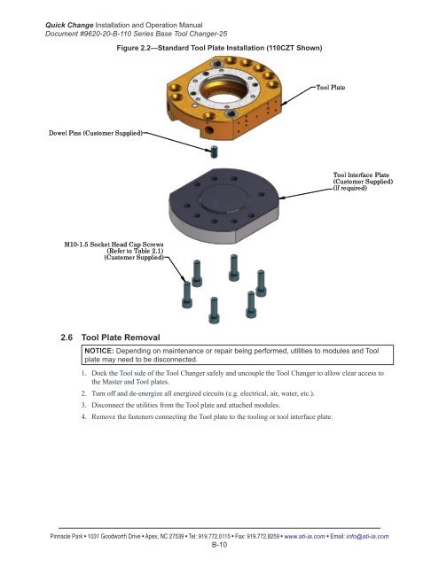
Figure 2.2—Standard Tool Plate Installation (110CZT Shown)<br />
Tool Plate<br />
Dowel Pins (Customer Supplied)<br />
Tool Interface Plate<br />
(Customer Supplied)<br />
(If required)<br />
M10-1.5 Socket Head Cap Screws<br />
(Refer to <strong>Table</strong> 2.1)<br />
(Customer Supplied)<br />
2.6 Tool Plate Removal<br />
NOTICE: Depending on maintenance or repair being performed, utilities to modules and Tool<br />
plate may need to be disconnected.<br />
1. Dock the Tool side <strong>of</strong> the Tool Changer safely and uncouple the Tool Changer to allow clear access to<br />
the Master and Tool plates.<br />
2. Turn <strong>of</strong>f and de-energize all energized circuits (e.g. electrical, air, water, etc.).<br />
3. Disconnect the utilities from the Tool plate and attached modules.<br />
4. Remove the fasteners connecting the Tool plate to the tooling or tool interface plate.<br />
Pinnacle Park • 1031 Goodworth Drive • Apex, NC 27539 • Tel: 919.772.0115 • Fax: 919.772.8259 • www.ati-ia.com • Email: info@ati-ia.com<br />
B-10