Table of Contents
ATI QC-110 Base Tool Changer Modular Manual
ATI QC-110 Base Tool Changer Modular Manual

Create successful ePaper yourself
Turn your PDF publications into a flip-book with our unique Google optimized e-Paper software.
Quick Change Installation and Operation Manual<br />
Document #9620-20-B-110 Series Base Tool Changer-25<br />
4. Maintenance<br />
WARNING: Do not perform maintenance or repair on Tool Changer or modules unless the<br />
Tool is safely supported or docked in the tool stand, all energized circuits (e.g. electrical,<br />
air, water, etc.) are turned <strong>of</strong>f, pressurized connections purged and power discharged from<br />
circuits in accordance with the customer’s safety practices and policies. Injury or equipment<br />
damage can occur with Tool not docked and energized circuits on. Dock the Tool safely in the<br />
tool stand, turn <strong>of</strong>f and discharge all energized circuits, purge all pressurized connections,<br />
verify all energized circuits are de-energized before performing maintenance or repair on Tool<br />
Changer or modules.<br />
NOTICE: The cleanliness <strong>of</strong> the work environment strongly influences the trouble free operation <strong>of</strong> the Tool<br />
Changer. The dirtier the environment, the greater the need for protection against debris. Protection <strong>of</strong> the entire<br />
EOAT, the Master, the Tool and all <strong>of</strong> the modules may be necessary. Protective measures include the following:<br />
1) Placement <strong>of</strong> tool stands away from debris generators.<br />
2) Covers incorporated into the tool stands.<br />
3) Guards, deflectors, air curtains, and similar devices built into the EOAT and the tool stand.<br />
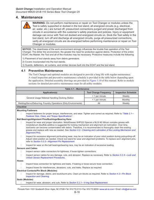
4.1 Preventive Maintenance<br />
The Tool Changer and optional modules are designed to provide a long life with regular maintenance.<br />
A visual inspection and preventive maintenance schedule is provided in the table below depending upon<br />
the application. Detailed assembly drawings are provided in Figure 5.10 <strong>of</strong> this manual. Refer to module<br />
sections for detailed preventive maintenance steps for all utility modules.<br />
<strong>Table</strong> 4.1—Maintenance<br />
Application(s) Tool Change Frequency Inspection Schedule<br />
General Usage Material Handling Docking Station<br />
> 1 per minute Weekly<br />
< 1 per minute Monthly<br />
Welding/Servo/Deburring, Foundry Operations (Dirty Environments) All Weekly<br />
Checklist<br />
Mounting Fasteners<br />
гг<br />
Inspect fasteners for proper torque, interferences, and wear. Tighten and correct as required. Refer to “<strong>Table</strong> 2.1—<br />
Fastener Size, Class, and Torque Specifications”.<br />
Ball Bearings/Alignment Pins/Bushings/Bearing Race<br />
гг<br />
гг<br />
гг<br />
Inspect for wear and proper lubrication. MobilGrease XHP222 Special a NLGI #2 lithium complex grease with<br />
molybdenum disulfide additive is suggested for locking mechanism and alignment pin lubrication. Over time,<br />
lubricants can become contaminated with debris. Therefore, it is recommended to thoroughly clean the existing<br />
grease and replace with new as needed. See Section 4.2—Cleaning and Lubrication <strong>of</strong> the Locking Mechanism and<br />
Alignment Pins.<br />
Inspect for excessive alignment pin/bushing wear, may be an indication <strong>of</strong> poor robot position during pickup/drop-<strong>of</strong>f.<br />
Adjust robot position as needed. Check tool stand for wear and alignment problems. To replace worn alignment pins,<br />
refer to Section 5.2.2—Alignment Pin Replacement.<br />
Inspect for wear on the ball bearings/bearing race, may be an indication <strong>of</strong> excessive loading.<br />
Sensors and Cables<br />
гг<br />
Inspect sensor cable connectors for tightness, if loose tighten connections.<br />
гг<br />
Inspect sensor cables for any damage, cuts, and abrasion. Replace as necessary. Refer to Section 5.2.4—Lock and<br />
Unlock Sensor Replacement Procedures.<br />
Hoses<br />
гг<br />
Inspect hose connection for tightness and leaks. If leaking or loose secure hose connection.<br />
гг<br />
Inspect hoses for interferences, abrasions, cuts, and leaks. Replace as required.<br />
Electrical Contacts/Pin Block (Modules)<br />
гг<br />
Inspect for damage, debris, and stuck/burnt pins. Clean pin blocks as required, Refer to Section 4.3—Pin Block<br />
Inspection and Cleaning.<br />
Seals (Modules)<br />
гг<br />
Inspect for wear, abrasion, and cuts. Refer to Section 5.2.1—V-ring Seal Replacement<br />
Pinnacle Park • 1031 Goodworth Drive • Apex, NC 27539 • Tel: 919.772.0115 • Fax: 919.772.8259 • www.ati-ia.com • Email: info@ati-ia.com<br />
B-18