Product Overview - Lumentron Electronic Kft.
Product Overview - Lumentron Electronic Kft.
Product Overview - Lumentron Electronic Kft.
Create successful ePaper yourself
Turn your PDF publications into a flip-book with our unique Google optimized e-Paper software.
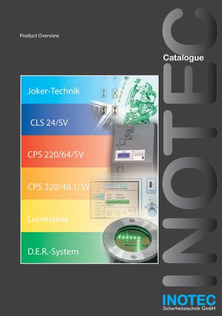
<strong>Product</strong> <strong>Overview</strong><br />
Catalogue<br />
Sicherheitstechnik GmbH
2<br />
INOTEC Sicherheitstechnik GmbH is a mediumsized<br />
business creating innovative and<br />
customer-oriented developments in the field<br />
of emergency and safety lighting.<br />
A dynamic team with flexible and competent<br />
staff provides reliable advice on all matters<br />
concerning products, planning and regulations.<br />
Modern, technically sophisticated products set<br />
new standards worldwide, such as emergency<br />
lighting systems with JOKER technology or<br />
the D.E.R. dynamic escape routing guidance<br />
system.<br />
This catalogue provides an overview of the<br />
various product groups available from INOTEC<br />
Sicherheitstechnik GmbH. Should you require<br />
further information, please do not hesitate<br />
to contact our regional technical sales staff<br />
directly.<br />
Copyright: INOTEC Sicherheitstechnik GmbH, Ense<br />
Reproduction and duplication, even of extracts,<br />
by approval of manufacturer only.<br />
Subject to technical changes.<br />
The emergency systems in this catalogue are<br />
not compatible to monitoring systems of type<br />
INOTEC SVPC, SV-central or multifunctional<br />
controller.<br />
INOTEC Sicherheitstechnik GmbH<br />
Contents<br />
Who and what we are<br />
Joker technology 3<br />
Page<br />
CLS 24/SV 4/5<br />
CPS 220/64/SV 6/7<br />
CPS 220/48.1/SV 8/9<br />
Luminaires 10/11<br />
D.E.R. system 12/13<br />
INOTEC Worldwide 14/15
Joker-Technik<br />
Benefi ts and function<br />
Function of Joker technology<br />
� Three switching modes can be operated<br />
simultaneously and in a mixed confi guration<br />
on INOTEC emergency lighting devices. In<br />
addition to the system, Joker electronic ballasts,<br />
or standard ballasts for INOTEC safety<br />
and emergency exit luminaires, are also<br />
required, or an INOTEC J/SV module/S is connected<br />
upstream of a third-party electronic<br />
ballast. On both components, the desired<br />
switching mode and monitoring address are<br />
confi gured using microswitches.<br />
� JOKER technology, patented by INOTEC,<br />
makes planning and installation of safety<br />
lighting systems much simpler resulting in<br />
signifi cant cost savings.<br />
� The example opposite shows to what extent<br />
reductions are possible in installation.<br />
� For the conventional installation with three<br />
required standard switching modes, maintained<br />
lighting, non-maintained lighting and<br />
switched maintained lighting, 6 fi nal circuits<br />
are required to provide 9 safety and emergency<br />
exit luminaires in this section of the<br />
building.<br />
� Using the JOKER technology can drastically<br />
reduce the number of circuits. In the<br />
example only 2 circuits are necessary since<br />
all switching modes can be combined as<br />
required within a circuit.<br />
� The different switching modes are only<br />
active during mains operation. In the event<br />
of a mains failure, all connected luminaires<br />
are powered by the battery and switched on,<br />
regardless of the default switching mode.<br />
German patent number:<br />
DE 19807844<br />
European patent number:<br />
EP 0939476<br />
Benefi ts of JOKER technology<br />
� Simple circuit routing planning<br />
� Amount of materials required is reduced<br />
� Shorter installation times<br />
� Optimized use of fi nal circuits<br />
� Subsequent or direct assignment of<br />
switching mode to each luminaire<br />
JOKER technology, the “original”<br />
Conventional<br />
installation<br />
Required:<br />
6 fi nal circuits<br />
Circuit 5<br />
Circuit 6<br />
JOKER technology with<br />
2 fi nal circuits<br />
Circuit 1<br />
Circuit 3 Circuit4<br />
Circuit 2<br />
Circuit 1 Circuit 2<br />
Maintained Non-maintained Switched maintained<br />
3
4<br />
With the CLS 24 system, INOTEC, as an innovative<br />
emergency lighting manufacturer, is<br />
setting a new trend which refl ects changes<br />
in the market for light fi xtures and current<br />
regulations.<br />
The self-suffi cient CLS 24 system only supplies<br />
luminaires within a fi re zone. No cost-intensive<br />
circuitry is therefore required and an extremely<br />
high level of safety is achieved.<br />
System properties<br />
� 24V emergency lighting system with automatic<br />
fault monitoring of the system and<br />
connected luminaires without additional<br />
data line.<br />
� To supply 24V INOTEC LED luminaires<br />
� Self-suffi cient system with “JOKER technology<br />
function”<br />
� Luminaires can be programmed, addressed<br />
and dimmed individually via the controller<br />
� Integrated logbook for recording all data<br />
� Controller with 4 x 20 character plain text<br />
display;<br />
confi gurable in various languages<br />
� Control, management and fault display for 20<br />
luminaires per output circuit<br />
� 4 output circuits in protection class III (SELV)<br />
for up to 20 luminaire addresses<br />
� 2 input switches can be freely assigned to<br />
each luminaire<br />
� Assignment to programmable dimming<br />
values also possible<br />
� Status info via system and luminaires in plain<br />
text using LEDs<br />
� Volt-free signalling contacts for external<br />
status display<br />
� Remote switch for blocking systems<br />
� Integrated InoWeb interface (optional)<br />
� Central dimming (optional)<br />
CLS 24/SV<br />
Function, Design and Properties<br />
Specifi cations<br />
� Mains connection: 230V AC +/-10%<br />
� Output voltage: 24V DC +/-20%<br />
� 12 Ah - 48 Ah system<br />
� Designed as housing for wall-mounting<br />
or sheet steel wall cabinet for surface<br />
installation.
CLS 24/SV<br />
Function, Design and Properties<br />
Through the use of the 24V technology in the<br />
CLS 24, the latest LED (light emitting diode)<br />
technology enables the construction of attractive<br />
luminaires which can be fi tted seamlessly<br />
into modern architecture due to their discreet<br />
design.<br />
With today’s 100 lumens per watt light output,<br />
the LEDs are not only suitable for use in emergency<br />
exit luminaires but also for anti-panic<br />
and safety lighting.<br />
In cinemas and theatres, it is possible to dim<br />
each luminaire individually via the controller. In<br />
emergency lighting mode, the unit is switched<br />
to 100% automatically.<br />
Comparison of conventional system with decentralised CLS 24 system concept<br />
T30<br />
1 . . . 20<br />
1 . . . 20<br />
1 . . . 20<br />
1 . . . 20<br />
Fire zone e.g. 1600m² Fire zone e.g. 1600m²<br />
UVS<br />
UVS<br />
UVS<br />
UVS<br />
1 . . . 20<br />
1 . . . 20<br />
1 . . . 20<br />
1 . . . 20<br />
1 . . . 20 1 . . . 20<br />
CLS<br />
UVS<br />
F 90<br />
E30<br />
CLS<br />
CLS<br />
CLS<br />
CLS<br />
CLS<br />
1 . . . 20<br />
In the event of mains power (HVS)<br />
failure � failure of entire safety lighting<br />
In the event of a fault in the cabling<br />
between the HVS and UVS � failure<br />
of all downstream UVS and therefore of<br />
safety lighting<br />
Due to self-contained CLS system �<br />
failure of safety lighting only in affected<br />
area<br />
5
6<br />
Controller with network/graphics capability<br />
� 5.6”’ TFT display<br />
� Intuitive single button operation<br />
� Password-protected programming<br />
� Integrated network connection (InoWeb)<br />
� USB interface<br />
The CPS 220 / 64 product family, with its<br />
modular design and additional available<br />
components, enables an optimised solution<br />
for all building circumstances. For smallerscale<br />
project planning the CPS 220 / 20’s<br />
central power system provides the same<br />
functionality.<br />
System properties<br />
� Modular unit design, various cabinet dimensions,<br />
battery rack or cabinets<br />
� Up to 128 circuits (64 via substations/64 in<br />
the system) each with 20 addresses can be<br />
supplied<br />
� Minimal service costs due to central monitoring<br />
of the entire safety lighting system and<br />
all connected luminaires<br />
� Automatic or manually triggered function<br />
testing unit with logbook for archiving status<br />
and error messages<br />
� Isolation testing unit<br />
� Isolating terminals for simple isolation measurement<br />
of luminaire circuits<br />
� Sealed OGI block battery with service life >10<br />
years<br />
� Electrically isolated BUS system inside and<br />
outside of the device<br />
� Separate monitoring and switching devices<br />
for maintained lighting/non-maintained<br />
lighting<br />
� Patented “JOKER technology”<br />
� Three input switches per circuit<br />
CPS 220/64/SV<br />
Function, Design and Properties<br />
� Management of up to 128 circuits<br />
(up to 2560 luminaires – 20 luminaires per circuit)<br />
� Fully automatic function monitoring including fault detection of individual luminaires and circuits<br />
without additional data line<br />
� Integrated logbook for recording all data over a period >2 years<br />
� Freely programmable switching modes<br />
� Various freely defi nable languages
CPS 220/64/SV<br />
Function, Design and Properties<br />
BUS substation<br />
For optimum implementation of projectspecifi<br />
c requirements, separate external BUS<br />
substations enable expansion of the central<br />
battery unit. The BUS substations in the fi re<br />
zone are also supplied with power via the<br />
3-wire supply lead in the event of a mains<br />
failure. Monitoring and programming is done<br />
using the central power system controller via<br />
the three wire bus line.<br />
These are also available in 24V technology,<br />
meaning that the CLS 24 system luminaires<br />
and their technical benefi ts are also available<br />
when using the central battery unit.<br />
Special D.E.R. system luminaires can also be<br />
connected to CPS 220 / 64 systems with a TFT<br />
controller and D.E.R circuit. Therefore, no extra<br />
D.E.R. controller is needed for dynamic escape<br />
route guidance. (available from quarter 3, 2010)<br />
Central monitoring<br />
Device information can be accessed via a web<br />
browser without installing additional software.<br />
The operator can therefore access the central<br />
power system’s status information from any<br />
computer in the network.<br />
An existing on-site network infrastructure may<br />
be used.<br />
Using the InoWeb Control software it is also<br />
possible to monitor complex installations<br />
consisting of multiple systems (also of different<br />
types, e.g. CPS 220/48/SV or<br />
CLS 24/SV) from a central location.<br />
For this simply connect the comfort TFT controller<br />
for the CPS 220/64/SV central power<br />
system with integrated InoWeb function to an<br />
existing network.<br />
1 basement db Operation System error: none<br />
Ground floor db Test System error<br />
1 first floor db Failure Circuit failure<br />
[no destination specified] blocked [DL and NL]<br />
7
8<br />
Mains CPS 220/SV<br />
Netz<br />
Netz<br />
Controller<br />
with display<br />
The CPS 220 / 48.1 product range provides<br />
a combination of the proven CPS 220 / 48<br />
technology and the functions of the CPS<br />
220 / 64 system. Up to 96 circuits are now<br />
supported by two internal device buses,<br />
each one capable of monitoring up to 20<br />
luminaires.<br />
System properties<br />
� Modular design of device, range of cabinet<br />
sizes, battery rack or cabinets<br />
� Up to 96 circuits (48 per device bus) each<br />
with 20 addresses can be supplied.<br />
� Minimal service costs due to central monitoring<br />
of the entire safety lighting system<br />
and all connected luminaires<br />
� Automatic or manually triggered function<br />
testing unit with logbook for archiving status<br />
and error messages<br />
� Isolation testing unit<br />
� Isolating terminals for simple isolation measurement<br />
of luminaire circuits<br />
� Sealed OGI block battery with service life >10<br />
years<br />
� Electrically isolated BUS system inside and<br />
outside of the device<br />
� Separate monitoring and switching devices<br />
for maintained lighting/non-maintained<br />
lighting<br />
� Patented “JOKER technology”: Mixed operation<br />
of maintained lighting, non-maintained<br />
lighting and switched maintained lighting<br />
� Three input switches per circuit<br />
Charger<br />
Battery 220V<br />
INOTEC<br />
Betrieb<br />
SV-ZENTRALE<br />
Batt.-<br />
01.07.95 12:00<br />
Betrieb<br />
Betrieb<br />
Störung Funktionstest 2.7.95 8:30<br />
Ladestörung<br />
Drucker Cetronics<br />
Mains<br />
monitoring<br />
Charge<br />
monitoring<br />
Ein<br />
Key-board<br />
10AT<br />
Batterie<br />
Change-over<br />
modules<br />
CPS 220/48.1/SV<br />
Function, Design and Properties<br />
Functionality:<br />
With a healthy mains supply, the consumer is<br />
supplied with power from the existing network<br />
and the battery is charged. In the event of<br />
failure of the normal supply, the consumer is<br />
supplied from the battery.<br />
Emergency and safety luminaires<br />
Emergency and safety luminaires
CPS 220/48.1/SV<br />
Function, Design and Properties<br />
Change-over devices<br />
� Individual circuit change-over device in 19”<br />
plug-in design with double pole fuse<br />
� Monitoring option confi gurable for each<br />
circuit (unmonitored, monitoring of circuits<br />
or individual luminaires)<br />
� Switching mode confi gurable for each<br />
circuit (maintained lighting, non-maintained<br />
lighting, switched maintained lighting, Joker<br />
mode)<br />
� Monitoring without data line<br />
� LEDs in front panel display switching mode<br />
and circuit status<br />
� Fully wired on 3-level 4mm² terminal with<br />
neutral isolation<br />
Störung<br />
Failure<br />
Batt.-Betrieb<br />
Bat.-Operation<br />
Betrieb<br />
Operation<br />
RTG<br />
RTG<br />
CPS-MTB 220 / 48.1<br />
Graphical CPS-MTB indicator board for CPS 220<br />
/ 48.1 for connection of up to 16 devices, displays<br />
fault reports in plain text on OLED display<br />
up to luminaire level.<br />
Rotating knob enables simple and intuitive<br />
operation.<br />
All connected devices can be blocked via the<br />
integrated remote switch input. The volt-free<br />
relay contacts enable alarms to be forwarded<br />
to other alarm systems.<br />
CP 4x2A CP 4x2A CP 4x2A CP 4x2A CP 4x2A CP 4x2A CP 4x2A CP 4x2A CP 4x2A CP 4x2A CP 4x2A CP 4x2A CP 4x2A CP 4x2A CP 4x2A CP 4x2A<br />
1 1 1 1 1 1 1 1 1 1 1 1 1 1 1 1<br />
F<br />
F<br />
F<br />
F<br />
F<br />
F<br />
F<br />
F<br />
F<br />
F<br />
F<br />
F<br />
F<br />
F<br />
F<br />
F<br />
3,15 A<br />
3,15 A<br />
3,15 A<br />
3,15 A<br />
3,15 A<br />
3,15 A<br />
3,15 A<br />
3,15 A<br />
3,15 A<br />
3,15 A<br />
3,15 A<br />
3,15 A<br />
3,15 A<br />
3,15 A<br />
3,15 A<br />
3,15 A<br />
2 2 2 2 2 2 2 2 2 2 2 2 2 2 2 2<br />
F<br />
F<br />
F<br />
F<br />
F<br />
F<br />
F<br />
F<br />
F<br />
F<br />
F<br />
F<br />
F<br />
F<br />
F<br />
F<br />
3,15 A<br />
3,15 A<br />
3,15 A<br />
3,15 A<br />
3,15 A<br />
3,15 A<br />
3,15 A<br />
3,15 A<br />
3,15 A<br />
3,15 A<br />
3,15 A<br />
3,15 A<br />
3,15 A<br />
3,15 A<br />
3,15 A<br />
3,15 A<br />
3 3 3 3 3 3 3 3 3 3 3 3 3 3 3 3<br />
F<br />
F<br />
F<br />
F<br />
F<br />
F<br />
F<br />
F<br />
F<br />
F<br />
F<br />
F<br />
F<br />
F<br />
F<br />
F<br />
3,15 A<br />
3,15 A<br />
3,15 A<br />
3,15 A<br />
3,15 A<br />
3,15 A<br />
3,15 A<br />
3,15 A<br />
3,15 A<br />
3,15 A<br />
3,15 A<br />
3,15 A<br />
3,15 A<br />
3,15 A<br />
3,15 A<br />
3,15 A<br />
4 4 4 4 4 4 4 4 4 4 4 4 4 4 4 4<br />
F<br />
F<br />
F<br />
F<br />
F<br />
F<br />
F<br />
F<br />
F<br />
F<br />
F<br />
F<br />
F<br />
F<br />
F<br />
F<br />
3,15 A<br />
3,15 A<br />
3,15 A<br />
3,15 A<br />
3,15 A<br />
3,15 A<br />
3,15 A<br />
3,15 A<br />
3,15 A<br />
3,15 A<br />
3,15 A<br />
3,15 A<br />
3,15 A<br />
3,15 A<br />
3,15 A<br />
3,15 A<br />
= BL / NM = BL / NM = BL / NM = BL / NM = BL / NM = BL / NM = BL / NM = BL / NM = BL / NM = BL / NM = BL / NM = BL / NM = BL / NM = BL / NM = BL / NM = BL / NM<br />
= DL / M = DL / M = DL / M = DL / M = DL / M = DL / M = DL / M = DL / M = DL / M = DL / M = DL / M = DL / M = DL / M = DL / M = DL / M = DL / M<br />
CPS 220 / 64<br />
Netz<br />
16AT<br />
Ladeteil 220V/7,5A<br />
INOTEC<br />
Betrieb<br />
Batt.-Betrieb<br />
Störung<br />
Lade-<br />
Störung<br />
Drucker Centronics<br />
Key-Board<br />
Reset<br />
R T<br />
CPS 1<br />
CPS 220 / 64<br />
Netz<br />
16AT<br />
Ladeteil 220V/7,5A<br />
Batterie<br />
10AT<br />
Ein<br />
CP 4x2A CP 4x2A CP 4x2A CP 4x2A CP 4x2A CP 4x2A CP 4x2A CP 4x2A CP 4x2A CP 4x2A CP 4x2A CP 4x2A CP 4x2A CP 4x2A CP 4x2A CP 4x2A<br />
1 1 1 1 1 1 1 1 1 1 1 1 1 1 1 1<br />
F<br />
F<br />
F<br />
F<br />
F<br />
F<br />
F<br />
F<br />
F<br />
F<br />
F<br />
F<br />
F<br />
F<br />
F<br />
F<br />
3,15 A<br />
3,15 A<br />
3,15 A<br />
3,15 A<br />
3,15 A<br />
3,15 A<br />
3,15 A<br />
3,15 A<br />
3,15 A<br />
3,15 A<br />
3,15 A<br />
3,15 A<br />
3,15 A<br />
3,15 A<br />
3,15 A<br />
3,15 A<br />
2 2 2 2 2 2 2 2 2 2 2 2 2 2 2 2<br />
F<br />
F<br />
F<br />
F<br />
F<br />
F<br />
F<br />
F<br />
F<br />
F<br />
F<br />
F<br />
F<br />
F<br />
F<br />
F<br />
3,15 A<br />
3,15 A<br />
3,15 A<br />
3,15 A<br />
3,15 A<br />
3,15 A<br />
3,15 A<br />
3,15 A<br />
3,15 A<br />
3,15 A<br />
3,15 A<br />
3,15 A<br />
3,15 A<br />
3,15 A<br />
3,15 A<br />
3,15 A<br />
3 3 3 3 3 3 3 3 3 3 3 3 3 3 3 3<br />
F<br />
F<br />
F<br />
F<br />
F<br />
F<br />
F<br />
F<br />
F<br />
F<br />
F<br />
F<br />
F<br />
F<br />
F<br />
F<br />
3,15 A<br />
3,15 A<br />
3,15 A<br />
3,15 A<br />
3,15 A<br />
3,15 A<br />
3,15 A<br />
3,15 A<br />
3,15 A<br />
3,15 A<br />
3,15 A<br />
3,15 A<br />
3,15 A<br />
3,15 A<br />
3,15 A<br />
3,15 A<br />
4 4 4 4 4 4 4 4 4 4 4 4 4 4 4 4<br />
F<br />
F<br />
F<br />
F<br />
F<br />
F<br />
F<br />
F<br />
F<br />
F<br />
F<br />
F<br />
F<br />
F<br />
F<br />
F<br />
3,15 A<br />
3,15 A<br />
3,15 A<br />
3,15 A<br />
3,15 A<br />
3,15 A<br />
3,15 A<br />
3,15 A<br />
3,15 A<br />
3,15 A<br />
3,15 A<br />
3,15 A<br />
3,15 A<br />
3,15 A<br />
3,15 A<br />
3,15 A<br />
= BL / NM = BL / NM = BL / NM = BL / NM = BL / NM = BL / NM = BL / NM = BL / NM = BL / NM = BL / NM = BL / NM = BL / NM = BL / NM = BL / NM = BL / NM = BL / NM<br />
= DL / M = DL / M = DL / M = DL / M = DL / M = DL / M = DL / M = DL / M = DL / M = DL / M = DL / M = DL / M = DL / M = DL / M = DL / M = DL / M<br />
INOTEC<br />
Betrieb<br />
Batt.-Betrieb<br />
Störung<br />
Lade-<br />
Störung<br />
Drucker Centronics<br />
Key-Board<br />
Reset<br />
R T<br />
Batterie<br />
10AT<br />
Ein<br />
CP 4x2A CP 4x2A CP 4x2A CP 4x2A CP 4x2A CP 4x2A CP 4x2A CP 4x2A CP 4x2A CP 4x2A CP 4x2A CP 4x2A CP 4x2A CP 4x2A CP 4x2A CP 4x2A<br />
1 1 1 1 1 1 1 1 1 1 1 1 1 1 1 1<br />
F<br />
F<br />
F<br />
F<br />
F<br />
F<br />
F<br />
F<br />
F<br />
F<br />
F<br />
F<br />
F<br />
F<br />
F<br />
F<br />
3,15 A<br />
3,15 A<br />
3,15 A<br />
3,15 A<br />
3,15 A<br />
3,15 A<br />
3,15 A<br />
3,15 A<br />
3,15 A<br />
3,15 A<br />
3,15 A<br />
3,15 A<br />
3,15 A<br />
3,15 A<br />
3,15 A<br />
3,15 A<br />
2 2 2 2 2 2 2 2 2 2 2 2 2 2 2 2<br />
F<br />
F<br />
F<br />
F<br />
F<br />
F<br />
F<br />
F<br />
F<br />
F<br />
F<br />
F<br />
F<br />
F<br />
F<br />
F<br />
3,15 A<br />
3,15 A<br />
3,15 A<br />
3,15 A<br />
3,15 A<br />
3,15 A<br />
3,15 A<br />
3,15 A<br />
3,15 A<br />
3,15 A<br />
3,15 A<br />
3,15 A<br />
3,15 A<br />
3,15 A<br />
3,15 A<br />
3,15 A<br />
3 3 3 3 3 3 3 3 3 3 3 3 3 3 3 3<br />
F<br />
F<br />
F<br />
F<br />
F<br />
F<br />
F<br />
F<br />
F<br />
F<br />
F<br />
F<br />
F<br />
F<br />
F<br />
F<br />
3,15 A<br />
3,15 A<br />
3,15 A<br />
3,15 A<br />
3,15 A<br />
3,15 A<br />
3,15 A<br />
3,15 A<br />
3,15 A<br />
3,15 A<br />
3,15 A<br />
3,15 A<br />
3,15 A<br />
3,15 A<br />
3,15 A<br />
3,15 A<br />
4 4 4 4 4 4 4 4 4 4 4 4 4 4 4 4<br />
F<br />
F<br />
F<br />
F<br />
F<br />
F<br />
F<br />
F<br />
F<br />
F<br />
F<br />
F<br />
F<br />
F<br />
F<br />
F<br />
3,15 A<br />
3,15 A<br />
3,15 A<br />
3,15 A<br />
3,15 A<br />
3,15 A<br />
3,15 A<br />
3,15 A<br />
3,15 A<br />
3,15 A<br />
3,15 A<br />
3,15 A<br />
3,15 A<br />
3,15 A<br />
3,15 A<br />
3,15 A<br />
= BL / NM = BL / NM = BL / NM = BL / NM = BL / NM = BL / NM = BL / NM = BL / NM = BL / NM = BL / NM = BL / NM = BL / NM = BL / NM = BL / NM = BL / NM = BL / NM<br />
= DL / M = DL / M = DL / M = DL / M = DL / M = DL / M = DL / M = DL / M = DL / M = DL / M = DL / M = DL / M = DL / M = DL / M = DL / M = DL / M<br />
CPS 220 / 64<br />
Netz<br />
16AT<br />
Ladeteil 220V/7,5A<br />
INOTEC<br />
Betrieb<br />
Batt.-Betrieb<br />
Störung<br />
Lade-<br />
Störung<br />
Drucker Centronics<br />
Key-Board<br />
Reset<br />
R T<br />
Batterie<br />
10AT<br />
Ein<br />
CP 4x2A CP 4x2A CP 4x2A CP 4x2A CP 4x2A CP 4x2A CP 4x2A CP 4x2A CP 4x2A CP 4x2A CP 4x2A CP 4x2A CP 4x2A CP 4x2A CP 4x2A CP 4x2A<br />
1 1 1 1 1 1 1 1 1 1 1 1 1 1 1 1<br />
F<br />
F<br />
F<br />
F<br />
F<br />
F<br />
F<br />
F<br />
F<br />
F<br />
F<br />
F<br />
F<br />
F<br />
F<br />
F<br />
3,15 A<br />
3,15 A<br />
3,15 A<br />
3,15 A<br />
3,15 A<br />
3,15 A<br />
3,15 A<br />
3,15 A<br />
3,15 A<br />
3,15 A<br />
3,15 A<br />
3,15 A<br />
3,15 A<br />
3,15 A<br />
3,15 A<br />
3,15 A<br />
2 2 2 2 2 2 2 2 2 2 2 2 2 2 2 2<br />
F<br />
F<br />
F<br />
F<br />
F<br />
F<br />
F<br />
F<br />
F<br />
F<br />
F<br />
F<br />
F<br />
F<br />
F<br />
F<br />
3,15 A<br />
3,15 A<br />
3,15 A<br />
3,15 A<br />
3,15 A<br />
3,15 A<br />
3,15 A<br />
3,15 A<br />
3,15 A<br />
3,15 A<br />
3,15 A<br />
3,15 A<br />
3,15 A<br />
3,15 A<br />
3,15 A<br />
3,15 A<br />
3 3 3 3 3 3 3 3 3 3 3 3 3 3 3 3<br />
F<br />
F<br />
F<br />
F<br />
F<br />
F<br />
F<br />
F<br />
F<br />
F<br />
F<br />
F<br />
F<br />
F<br />
F<br />
F<br />
3,15 A<br />
3,15 A<br />
3,15 A<br />
3,15 A<br />
3,15 A<br />
3,15 A<br />
3,15 A<br />
3,15 A<br />
3,15 A<br />
3,15 A<br />
3,15 A<br />
3,15 A<br />
3,15 A<br />
3,15 A<br />
3,15 A<br />
3,15 A<br />
4 4 4 4 4 4 4 4 4 4 4 4 4 4 4 4<br />
F<br />
F<br />
F<br />
F<br />
F<br />
F<br />
F<br />
F<br />
F<br />
F<br />
F<br />
F<br />
F<br />
F<br />
F<br />
F<br />
3,15 A<br />
3,15 A<br />
3,15 A<br />
3,15 A<br />
3,15 A<br />
3,15 A<br />
3,15 A<br />
3,15 A<br />
3,15 A<br />
3,15 A<br />
3,15 A<br />
3,15 A<br />
3,15 A<br />
3,15 A<br />
3,15 A<br />
3,15 A<br />
= BL / NM = BL / NM = BL / NM = BL / NM = BL / NM = BL / NM = BL / NM = BL / NM = BL / NM = BL / NM = BL / NM = BL / NM = BL / NM = BL / NM = BL / NM = BL / NM<br />
= DL / M = DL / M = DL / M = DL / M = DL / M = DL / M = DL / M = DL / M = DL / M = DL / M = DL / M = DL / M = DL / M = DL / M = DL / M = DL / M<br />
Netz<br />
16AT<br />
Ladeteil 220V/7,5A<br />
CPS 2 CPS 8<br />
CP 4x2A CP 4x2A CP 4x2A CP 4x2A CP 4x2A CP 4x2A CP 4x2A CP 4x2A CP 4x2A CP 4x2A CP 4x2A CP 4x2A CP 4x2A CP 4x2A CP 4x2A CP 4x2A<br />
1 1 1 1 1 1 1 1 1 1 1 1 1 1 1 1<br />
F<br />
F<br />
F<br />
F<br />
F<br />
F<br />
F<br />
F<br />
F<br />
F<br />
F<br />
F<br />
F<br />
F<br />
F<br />
F<br />
3,15 A<br />
3,15 A<br />
3,15 A<br />
3,15 A<br />
3,15 A<br />
3,15 A<br />
3,15 A<br />
3,15 A<br />
3,15 A<br />
3,15 A<br />
3,15 A<br />
3,15 A<br />
3,15 A<br />
3,15 A<br />
3,15 A<br />
3,15 A<br />
2 2 2 2 2 2 2 2 2 2 2 2 2 2 2 2<br />
F<br />
F<br />
F<br />
F<br />
F<br />
F<br />
F<br />
F<br />
F<br />
F<br />
F<br />
F<br />
F<br />
F<br />
F<br />
F<br />
3,15 A<br />
3,15 A<br />
3,15 A<br />
3,15 A<br />
3,15 A<br />
3,15 A<br />
3,15 A<br />
3,15 A<br />
3,15 A<br />
3,15 A<br />
3,15 A<br />
3,15 A<br />
3,15 A<br />
3,15 A<br />
3,15 A<br />
3,15 A<br />
3 3 3 3 3 3 3 3 3 3 3 3 3 3 3 3<br />
F<br />
F<br />
F<br />
F<br />
F<br />
F<br />
F<br />
F<br />
F<br />
F<br />
F<br />
F<br />
F<br />
F<br />
F<br />
F<br />
3,15 A<br />
3,15 A<br />
3,15 A<br />
3,15 A<br />
3,15 A<br />
3,15 A<br />
3,15 A<br />
3,15 A<br />
3,15 A<br />
3,15 A<br />
3,15 A<br />
3,15 A<br />
3,15 A<br />
3,15 A<br />
3,15 A<br />
3,15 A<br />
4 4 4 4 4 4 4 4 4 4 4 4 4 4 4 4<br />
F<br />
F<br />
F<br />
F<br />
F<br />
F<br />
F<br />
F<br />
F<br />
F<br />
F<br />
F<br />
F<br />
F<br />
F<br />
F<br />
3,15 A<br />
3,15 A<br />
3,15 A<br />
3,15 A<br />
3,15 A<br />
3,15 A<br />
3,15 A<br />
3,15 A<br />
3,15 A<br />
3,15 A<br />
3,15 A<br />
3,15 A<br />
3,15 A<br />
3,15 A<br />
3,15 A<br />
3,15 A<br />
= BL / NM = BL / NM = BL / NM = BL / NM = BL / NM = BL / NM = BL / NM = BL / NM = BL / NM = BL / NM = BL / NM = BL / NM = BL / NM = BL / NM = BL / NM = BL / NM<br />
= DL / M = DL / M = DL / M = DL / M = DL / M = DL / M = DL / M = DL / M = DL / M = DL / M = DL / M = DL / M = DL / M = DL / M = DL / M = DL / M<br />
CPS 220 / 64<br />
Netz<br />
16AT<br />
Ladeteil 220V/7,5A<br />
INOTEC<br />
Betrieb<br />
Batt.-Betrieb<br />
Störung<br />
Lade-<br />
Störung<br />
Drucker Centronics<br />
Key-Board<br />
Reset<br />
R T<br />
Batterie<br />
10AT<br />
Ein<br />
CPS 1 CPS 2 CPS 8<br />
CPS 220 / 64<br />
CPS 220 / 64<br />
Netz<br />
16AT<br />
Ladeteil 220V/7,5A<br />
INOTEC<br />
Betrieb<br />
Batt.-Betrieb<br />
Störung<br />
Lade-<br />
Störung<br />
Drucker Centronics<br />
Key-Board<br />
Reset<br />
R T<br />
Batterie<br />
10AT<br />
Ein<br />
CP 4x2A CP 4x2A CP 4x2A CP 4x2A CP 4x2A CP 4x2A CP 4x2A CP 4x2A CP 4x2A CP 4x2A CP 4x2A CP 4x2A CP 4x2A CP 4x2A CP 4x2A CP 4x2A<br />
1 1 1 1 1 1 1 1 1 1 1 1 1 1 1 1<br />
F<br />
F<br />
F<br />
F<br />
F<br />
F<br />
F<br />
F<br />
F<br />
F<br />
F<br />
F<br />
F<br />
F<br />
F<br />
F<br />
3,15 A<br />
3,15 A<br />
3,15 A<br />
3,15 A<br />
3,15 A<br />
3,15 A<br />
3,15 A<br />
3,15 A<br />
3,15 A<br />
3,15 A<br />
3,15 A<br />
3,15 A<br />
3,15 A<br />
3,15 A<br />
3,15 A<br />
3,15 A<br />
2 2 2 2 2 2 2 2 2 2 2 2 2 2 2 2<br />
F<br />
F<br />
F<br />
F<br />
F<br />
F<br />
F<br />
F<br />
F<br />
F<br />
F<br />
F<br />
F<br />
F<br />
F<br />
F<br />
3,15 A<br />
3,15 A<br />
3,15 A<br />
3,15 A<br />
3,15 A<br />
3,15 A<br />
3,15 A<br />
3,15 A<br />
3,15 A<br />
3,15 A<br />
3,15 A<br />
3,15 A<br />
3,15 A<br />
3,15 A<br />
3,15 A<br />
3,15 A<br />
3 3 3 3 3 3 3 3 3 3 3 3 3 3 3 3<br />
F<br />
F<br />
F<br />
F<br />
F<br />
F<br />
F<br />
F<br />
F<br />
F<br />
F<br />
F<br />
F<br />
F<br />
F<br />
F<br />
3,15 A<br />
3,15 A<br />
3,15 A<br />
3,15 A<br />
3,15 A<br />
3,15 A<br />
3,15 A<br />
3,15 A<br />
3,15 A<br />
3,15 A<br />
3,15 A<br />
3,15 A<br />
3,15 A<br />
3,15 A<br />
3,15 A<br />
3,15 A<br />
4 4 4 4 4 4 4 4 4 4 4 4 4 4 4 4<br />
F<br />
F<br />
F<br />
F<br />
F<br />
F<br />
F<br />
F<br />
F<br />
F<br />
F<br />
F<br />
F<br />
F<br />
F<br />
F<br />
3,15 A<br />
3,15 A<br />
3,15 A<br />
3,15 A<br />
3,15 A<br />
3,15 A<br />
3,15 A<br />
3,15 A<br />
3,15 A<br />
3,15 A<br />
3,15 A<br />
3,15 A<br />
3,15 A<br />
3,15 A<br />
3,15 A<br />
3,15 A<br />
= BL / NM = BL / NM = BL / NM = BL / NM = BL / NM = BL / NM = BL / NM = BL / NM = BL / NM = BL / NM = BL / NM = BL / NM = BL / NM = BL / NM = BL / NM = BL / NM<br />
= DL / M = DL / M = DL / M = DL / M = DL / M = DL / M = DL / M = DL / M = DL / M = DL / M = DL / M = DL / M = DL / M = DL / M = DL / M = DL / M<br />
INOTEC<br />
Betrieb<br />
Batt.-Betrieb<br />
Störung<br />
Lade-<br />
Störung<br />
Drucker Centronics<br />
Key-Board<br />
Reset<br />
R T<br />
Batterie<br />
10AT<br />
Ein<br />
9
10<br />
Exit-luminaires<br />
Function, Design and Properties<br />
By using the latest LED technologies for<br />
emergency exit luminaires, these comply<br />
with the current regulations and standards<br />
and will help you keep operating and maintenance<br />
costs to a minimum.<br />
INOTEC emergency exit luminaires are available<br />
in many different specifi cations so they can<br />
be integrated in keeping with the architecture.<br />
Colour, material, size or mounting options - we<br />
can supply you with the right luminaire for any<br />
application.<br />
Should you fail to fi nd the right luminaire for<br />
your project in our standard range, simply<br />
contact us. The INOTEC design department will<br />
work with you to develop the perfect solution<br />
to your problem.<br />
We will happily also draft your own personal<br />
pictogram with you for luminaires not falling<br />
within the scope of the standard.<br />
Innovation in emergency exit luminaires<br />
In spite of its shallow housing depth, the new<br />
INOTEC panel luminaire’s brightness and<br />
homogenous illumination make it stand out.<br />
It is therefore ideally suited to use in bright<br />
environments. Its clean modern contours mean<br />
it can be fi tted into the building’s architecture<br />
quite unobtrusively. (available from quarter 3,<br />
2010)
Safety luminaires<br />
Function, Design and Properties<br />
LED technology is also increasingly widespread<br />
in the fi eld of safety lighting. Bright<br />
LEDs now provide comparable values at the<br />
same suspension height and lighting level<br />
as a conventional fl uorescent lamp and for<br />
a longer life time. INOTEC therefore offers a<br />
5-year warranty on all LED illuminants.<br />
INOTEC safety luminaires using LED technology<br />
are available in the widest range of<br />
specifi cations. Whether you are looking for an<br />
architectural eye-catcher or something a little<br />
more unobtrusive, INOTEC has just the thing in<br />
its range of LED luminaires.<br />
As standard all monitored INOTEC LED luminaires<br />
can be dimmed and switched to during<br />
mains operation individually to illuminate<br />
escape routes at full brightness. A function<br />
frequently used in theatres or cinemas.<br />
For use in harsh environments such as outside<br />
or in industrial areas, the robust INOTEC stainless<br />
steel luminaires with a high protection<br />
category is ideal.<br />
11
12<br />
Are escape routes always escape routes?<br />
Emergency exit luminaires with fi xed directional<br />
signs are used to mark escape routes<br />
and fulfi l the task of enabling people to reach<br />
safe locations in the event of a power failure<br />
or a necessary evacuation.<br />
But what happens if fi re and smoke are blocking<br />
the nearest escape route?<br />
What to do when heavy smoke emissions<br />
mean it is no longer possible to work out<br />
where you are?<br />
How do you fi nd the escape route when the<br />
escape route sign is no longer visible?<br />
Do you have anything against a higher level<br />
of safety?<br />
INOTEC Sicherheitstechnik GmbH has taken on<br />
the problem of smoky escape routes with the<br />
aim of complementing fi xed, unchangeable<br />
escape route signage with dynamic escape<br />
route guidance.<br />
A dynamic system has to fulfi l two key tasks,<br />
namely on the one hand preventing anyone<br />
from escaping into an escape route that is<br />
D.E.R.-System<br />
Trying new ways - follow us!<br />
already smoke-fi lled and on the other, ensuring<br />
that the people in smoky areas can still fi nd<br />
their way to the escape route.<br />
The solution is the Dynamic Escape Routing<br />
guidance system (D.E.R.). Luminaires with<br />
integrated LED matrices ensure not only fi xed<br />
escape route signage but also display an<br />
alternative escape route and visible blocking of<br />
the escape route with a cross of red LEDs. For<br />
why should an escape route remain signposted<br />
when it is smoky and no longer usable?<br />
Use of the Dynamic Escape Routing (D.E.R.)<br />
guidance system therefore signifi cantly<br />
improves personal protection in the event of<br />
a fi re and helps avoid or reduce panic and also<br />
speeds up evacuation of a building, not only in<br />
the event of a fi re.
D.E.R.-System<br />
Dynamic Escape Routing System<br />
Functionality of the D.E.R. system<br />
The D.E.R. system corresponds with the building’s<br />
existing fi re detection system. The D.E.R.<br />
controller analyses the defi ned messages<br />
from the fi re detection system via an interface<br />
and activates the escape route guidance<br />
plan stored in the controller. Should the fi re<br />
or smoke spread further, the D.E.R. system can<br />
respond by activating other escape route plans<br />
and the rearrange the luminaires accordingly.<br />
Regulations<br />
As a result of use of the innovative D.E.R.<br />
system in airports, clinics, theatres,<br />
train stations etc., there has also been<br />
a response in terms of regulations. In<br />
January 2001, the German Association of<br />
Commercial and Industrial Workers’ Compensation<br />
Insurance Carriers (HVBG) issued<br />
the set of rules BGR 216 “Visible Safety Guidance<br />
Systems (incl. Safety Lighting)” in which<br />
the use of low level safety guidance systems<br />
is recommended for high-risk buildings. These<br />
include, for example, buildings containing a<br />
high percentage of external people and those<br />
with a high percentage of people with reduced<br />
mobility (bedridden or disabled people).<br />
In the Technical Rules for Workplaces (ASR<br />
A3.4/3), “Safety Lighting, Visible Safety Guidance<br />
Systems” ASR A3.4/2 of May 2009, the<br />
Committee on Workplaces (ASTA) describes<br />
in detail the use of visible safety guidance<br />
systems for workplaces with reference to ASR<br />
A2.3, which in turn governs the scenarios in<br />
which the use of a visible safety guidance system<br />
is necessary for escape routes.<br />
Fire Safety Award<br />
The D.E.R. system was honoured by fi re safety<br />
experts as a key<br />
development for<br />
increasing the<br />
safety of people by<br />
being awarded the<br />
Germany Fire Safety<br />
Award 2004 .<br />
13
14<br />
INOTEC world-wide<br />
Made in Germany<br />
Since the company was founded in 1995,<br />
INOTEC Sicherheitstechnik GmbH has been<br />
supporting you in all areas associated with<br />
the issue of safety and emergency lighting<br />
and has established itself as an expert on<br />
the market.<br />
The products designed<br />
in the in-house design<br />
department ensure the<br />
requisite safety in many<br />
properties, both inside<br />
and out. Using the latest<br />
software, the products<br />
are developed<br />
in accordance with<br />
applicable standards<br />
and regulations.<br />
Made in Germany<br />
A continuously monitored production process<br />
and qualifi ed production staff ensure INOTEC’s<br />
well-known quality and the “Made in Germany”<br />
quality seal. Final assembly and examination of<br />
our systems and luminaires takes place in our<br />
main factory in Ense.
INOTEC world-wide<br />
Always close to our customers<br />
Our large domestic and overseas sales network<br />
is available to assist you in emergency and<br />
safety lighting matters and planning within<br />
your projects.<br />
For maintenance and servicing of emergency<br />
and safety lighting systems, there are eleven<br />
suitable customer service representatives<br />
available in the various regions of Germany.<br />
Overseas this is carried out by staff from our<br />
agencies trained at INOTEC.<br />
If you are unable to fi nd the right solution<br />
for your problem within our product range,<br />
simply contact us. With your help we will come<br />
up with a project-specifi c solution for your<br />
property.<br />
Outside Germany our products<br />
are available through our foreign<br />
sales partners:<br />
� Belgium<br />
� Denmark<br />
� Italy<br />
� Luxemburg<br />
� The Netherlands<br />
� Norway<br />
� Austria<br />
� Poland<br />
� Portugal<br />
� Romania<br />
� Switzerland<br />
� Slovakia<br />
� Czech Republic<br />
� Hungary<br />
� United Arab Emirates<br />
Sales Agencies<br />
Customer Service<br />
15
16<br />
INOTEC Sicherheitstechnik GmbH<br />
Am Buschgarten 17<br />
D - 59 469 Ense<br />
Tel +49 29 38/97 30-0<br />
Fax +49 29 38/97 30-29<br />
info@inotec-licht.de<br />
www.inotec-licht.de<br />
Sicherheitstechnik GmbH<br />
707 006 04/2010


