Catalogue ELS/SV - Lumentron Electronic Kft.
Catalogue ELS/SV - Lumentron Electronic Kft.
Catalogue ELS/SV - Lumentron Electronic Kft.

Create successful ePaper yourself
Turn your PDF publications into a flip-book with our unique Google optimized e-Paper software.
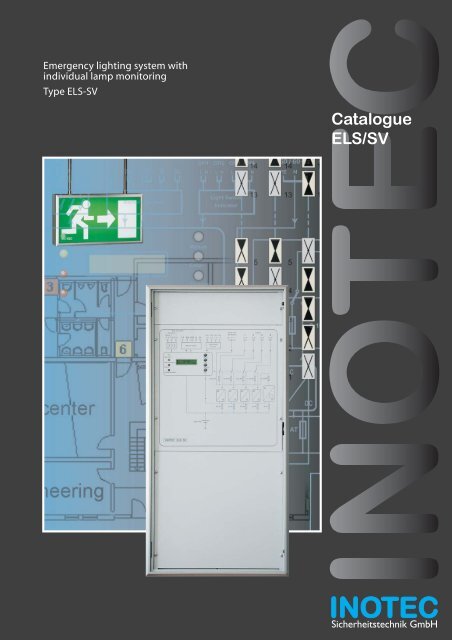
Emergency lighting system with<br />
individual lamp monitoring<br />
Type <strong>ELS</strong>-<strong>SV</strong><br />
<strong>Catalogue</strong><br />
<strong>ELS</strong>/<strong>SV</strong><br />
Sicherheitstechnik GmbH
INOTEC a company with the target to<br />
create innovative and customer<br />
oriented solutions for the Emergency<br />
Lighting market.<br />
A dynamic team of highly professional<br />
and flexible employees covers all<br />
aspects regarding products,<br />
engineering and standards.<br />
Modern, technical products create<br />
world wide new standards, i.e. JOKER<br />
technology for Emergency Lighting<br />
Systems or the Dynamic Escape<br />
Routing concept realised in the D.E.R.<br />
System.<br />
Copyright: INOTEC Sicherheitstechnik GmbH, Ense<br />
Publications and copies, even partial, only with<br />
maufacturers permission.<br />
Subject to technical changes<br />
Batt.-Operation<br />
Operation<br />
Failure<br />
1 2 3 4 5 6 FS 24V RTG B SL<br />
Operation<br />
Batt.-Operation<br />
Failure<br />
Charging failure<br />
Remote Control<br />
Menue<br />
Enter<br />
Change<br />
Test<br />
CH1 CH2 CH3 CH4<br />
L N L N L N L N<br />
Light Switch<br />
Indicator<br />
3,15 AT<br />
Content Page<br />
The <strong>ELS</strong>-<strong>SV</strong> emergency lighting system 3-4<br />
<strong>ELS</strong>-<strong>SV</strong> and Joker technology 5-6<br />
Installation sample 7<br />
Central monitoring<br />
and data protection<br />
8-9<br />
Advantages of monitored systems 10-11<br />
Components, technical data<br />
and specification text<br />
12-15<br />
Battery current and<br />
luminaire/ballast details<br />
12<br />
DPÜ - three phase monitor 12<br />
MTB - mimic panel 12<br />
<strong>SV</strong> - controller 13<br />
<strong>SV</strong> - computer 13<br />
<strong>Electronic</strong> ballast's and <strong>SV</strong>-luminaire modules 14<br />
<strong>ELS</strong> - <strong>SV</strong> emergency lighting system 15<br />
3,15 AT<br />
230V / AC<br />
output<br />
50 / 60 Hz 4<br />
PE N L<br />
3,15 AT<br />
1<br />
NLPE<br />
2<br />
NLPE<br />
3,15 AT<br />
3<br />
NLPE<br />
3,15 AT<br />
NLPE
<strong>ELS</strong> - <strong>SV</strong><br />
The INOTEC emergency lighting system with JOKER - Technology<br />
Features<br />
Supply and automatic function<br />
monitoring of upto 60 safety- and exit<br />
luminaries<br />
Operation of switched maintained-,<br />
maintained- and non-maintained-<br />
luminaries on one circuit<br />
Display of faulty luminaries with<br />
location (optional)<br />
Automatic function- and battery<br />
duration test of emergency lighting<br />
system with battery-circuit, internal<br />
circuits and every connected<br />
luminaire<br />
Display of failures, status information<br />
during normal operation and test<br />
conditions<br />
Selectable 1h or 3h operation time<br />
Compact and flexible<br />
Ideal for use within one fire-zone<br />
only<br />
No data line required<br />
Mix and match all possible<br />
switching modes on one circuit<br />
Easy to install<br />
Central battery replacement instead<br />
of time consuming changes on<br />
self-contained luminaries.<br />
Centralised automatic failure info<br />
allows spot-on service<br />
Automatic function- and battery<br />
duration tests<br />
Connection possibilities to building<br />
managment systems or in-house<br />
central monitors<br />
High performance and safety-level<br />
due to decentralised installation<br />
Compact assembly, depth just 110mm<br />
Attractive, elegant housing with<br />
clear perspec door<br />
The <strong>ELS</strong> - <strong>SV</strong> is the first ever built<br />
compact low load (480 Watt)<br />
emergency lighting system with<br />
JOKER - Technology.<br />
3
4<br />
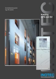
The free programmable control<br />
module with two-line liquid crystal<br />
display for plain text information<br />
has three main tasks:<br />
Monitor and control all internal<br />
functions and test-cycles, allow<br />
manual interaction<br />
Display all panel and luminaire<br />
information<br />
(failure and status info)<br />
Safe all information concerning tests,<br />
status of luminaries and panel for<br />
log-book purpose<br />
The display shows:<br />
Battery voltage<br />
Battery charging current<br />
Battery discharge current during test<br />
or emergency operation<br />
Charging failures<br />
- battery voltage to high / low<br />
- interrupted charge circuit<br />
- required duration test time not<br />
achieved<br />
Luminaire failure<br />
LED display the following<br />
mandatory status info:<br />
Operation (mains supply healthy)<br />
Batt.-Operation<br />
Operation<br />
Failure<br />
1 2 3 4 5 6<br />
Battery operation (test or mains<br />
failure)<br />
Failure (luminaire-, system- or mains<br />
Remote Control<br />
failure)<br />
Charging failure<br />
Operation<br />
Batt.-Operation<br />
Failure<br />
Charging failure<br />
The four push-buttons next to the<br />
display allow the programming of the<br />
system, the manual release of tests and<br />
the status- and failure interrogation for<br />
230V / AC<br />
output<br />
the individual CH1 CH2 system. CH3 CH4The<br />
pre-set 50 / 60 tests Hz 1 2 3 4<br />
FS 24V RTG B SL L N L N L N L N PE N L<br />
NLPE NLPE NLPE NLPE<br />
(function-test usually every 7 days,<br />
battery duration test usually every 12<br />
month) are Light free Switch programmable. The<br />
display text Indicator is adapted to the native<br />
language.<br />
Menue<br />
Enter<br />
Change<br />
Test<br />
3,15 AT<br />
<strong>ELS</strong> - <strong>SV</strong><br />
Control module, charger and change-over devices<br />
3,15 AT<br />
3,15 AT<br />
Every INOTEC emergency lighting<br />
system contains components<br />
guaranteeing, together with the<br />
connected luminaries, a maximum<br />
on function and safety.<br />
The constant current charger 3 Amps is<br />
monitored via the control module.<br />
The battery recharging time is < 10 h.<br />
Every one of the 4 change-over devices<br />
supplies up to 15 INOTEC safety- or exit<br />
luminaries. During mains supply 230V,<br />
50/60Hz are present on the output; in<br />
emergency or test mode this supply<br />
comes from the battery pack.<br />
3,15 AT<br />
3,15 AT
<strong>ELS</strong> - <strong>SV</strong><br />
JOKER - Technology<br />
Joker-technology function<br />
Each <strong>ELS</strong>-<strong>SV</strong> change-over device is<br />
able to foster three differing luminaire<br />
switching modes on the same output<br />
at the same time (see page 4).<br />
In addition to the system, luminaries<br />
with Joker high frequency electronic<br />
ballast (common standard on INOTEC<br />
luminaries) or Joker switch modules,<br />
J/<strong>SV</strong>-module/S, for third party<br />
electronic ballast, must be used.<br />
These components allow the easy<br />
setting of monitoring address and<br />
luminaire mode.<br />
The patented JOKER-technology of<br />
INOTEC reduces the design- and<br />
installation time and cuts down on<br />
material cost.<br />
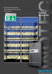
The sample to the right shows the<br />
reduction on installation material and<br />
circuit layout.<br />
Conventional emergency lighting<br />
sys-tems and installations with the<br />
three possible standard switching<br />
modes maintained (DL)-,<br />
non-maintained (BL)- and switched<br />
maintained (gDL) mode, require 6 final<br />
end circuits to feed 9 luminaries in a<br />
part of the building shown.<br />
The Joker-Technology reduces the<br />
number of circuits required. Our sample<br />
needs only 2 final end circuits to feed<br />
the same number of luminaries due to<br />
the fact that the operation of all switching<br />
modes on one circuit is possible.<br />
The maintained and switched<br />
main-tained luminaries are active<br />
during mains presence. During mains<br />
failure however, all luminaries will be<br />
switched on and supplied by the<br />
battery (see page 6).<br />
Advantages of the Joker-technology<br />
Simple design and engineering<br />
Reduced installation material<br />
content (cable reductions, see page<br />
6 - non-maintained mode, sense<br />
input)<br />
Conventional installation<br />
requires<br />
6 final end circuits<br />
circuit 5<br />
circuit 6<br />
circuit 1<br />
Joker-technology with<br />
2 final end circuits<br />
circuit 3 circuit 4<br />
Maintained mode Non-maintained<br />
mode<br />
Cut down on installation time<br />
Higher load level for final end<br />
circuits<br />
Switching mode settable on each<br />
luminaire<br />
circuit 2<br />
circuit 1 circuit 2<br />
Switched maintained<br />
mode<br />
5
6<br />
L<br />
N<br />
PE<br />
Maintained-, non-maintained- and<br />
switched maintained mode<br />
230V / AC<br />
50 / 60 Hz<br />
3,15 AT<br />
24V / Pb<br />
Maintained light (DL)<br />
Exit- and safety luminaries in<br />
maintained mode light in any<br />
operational state. Under mains<br />
conditions they are supplied with<br />
Batt.-Operation<br />
Operation<br />
Failure<br />
manually CH1 or CH2 automatically CH3 CH4 released test<br />
1 2 3 4 5 6 FS 24V RTG B SL(function-<br />
L N or L Nbattery<br />
L N L duration N PE test). N The L<br />
230/240V 50/60Hz via the change-over<br />
device and the output terminals<br />
(WR1-L,N,PE)<br />
In the event of a mains failure the<br />
change-over contact switches to the<br />
and Operation feeds the luminaries.<br />
Batt.-Operation<br />
Failure<br />
N L PE<br />
DC<br />
10 AT<br />
DC<br />
Charging failure<br />
N L PE<br />
WR1<br />
N-<br />
N-<br />
In<br />
L+<br />
L+<br />
Remote Control<br />
battery side, the 24V battery voltage is<br />
converted into a higher DC voltage<br />
BL DL gDL<br />
J-EVG 4-13 <strong>SV</strong><br />
0<br />
1<br />
9<br />
Zehner Einer<br />
2<br />
8<br />
3 4 5 6 7<br />
0<br />
1<br />
9<br />
2<br />
8<br />
3 4 5 6 7<br />
J-EVG 4-13 <strong>SV</strong> 1<br />
860 004 2<br />
Adresse Temp.-Test<br />
UN:<br />
AC 230V 50 / 60Hz<br />
DC 176 - 264 V<br />
tc<br />
tc=70°C max<br />
λ : 0,95 INOTEC Betriebsart<br />
ta: BL (-15 bis 65°C) DL (-15 bis 50°C)<br />
EMC: gem./acc to EN 55015<br />
Geeignet für Anlagen gem. /acc. to EN 50172 BL DL<br />
Non-maintained light (BL)<br />
Safety luminaries in non-maintained<br />
mode only light when the normal<br />
lighting fails (mains failure) or during a<br />
BL-setting of the electronic ballast<br />
blocks the function in mains supply.<br />
Light Switch<br />
Mails failure Indicator or test trigger the system<br />
to change over to battery supply. The<br />
converted DC voltage feeds now the<br />
lamp via the J-EVG or J/<strong>SV</strong>-module.<br />
Menue<br />
Enter<br />
Change<br />
Test<br />
N-<br />
N-<br />
In<br />
L+<br />
L+<br />
0<br />
1<br />
9<br />
Lampe: 4-13 W<br />
TL / TC / TCD- EL<br />
3<br />
4<br />
3,15 AT<br />
J-EVG 4-13 <strong>SV</strong><br />
Zehner Einer<br />
2<br />
8<br />
3 4 5 6 7<br />
0<br />
1<br />
9<br />
2<br />
8<br />
3 4 5 6 7<br />
J-EVG 4-13 <strong>SV</strong> 1<br />
860 004 2<br />
Adresse Temp.-Test<br />
UN:<br />
AC 230V 50 / 60Hz<br />
DC 176 - 264 V<br />
tc<br />
tc=70°C max<br />
λ : 0,95 INOTEC Betriebsart<br />
ta: BL (-15 bis 65°C) DL (-15 bis 50°C)<br />
EMC: gem./acc to EN 55015<br />
Geeignet für Anlagen gem. /acc. to EN 50172 BL DL<br />
Lampe: 4-13 W<br />
TL / TC / TCD- EL<br />
3<br />
4<br />
3,15 AT<br />
<strong>ELS</strong> - <strong>SV</strong><br />
Switching modes with JOKER - Technology<br />
230V / AC<br />
output<br />
50 / 60 Hz 4<br />
3,15 AT<br />
Using the Joker-Technology the<br />
output of the <strong>ELS</strong>-<strong>SV</strong> system is set for<br />
maintained mode. The system changes<br />
to battery supply if mains supply fails.<br />
The luminaire modes are settable on<br />
the high frequency ballast (INOTEC<br />
J-EVG see page 14) or monitoring<br />
module (INOTEC J/<strong>SV</strong>-module see<br />
page 14).<br />
N-<br />
N-<br />
In<br />
L+<br />
L+<br />
Switched maintained light (gDL)<br />
Safety luminaire operating in switched<br />
maintained mode light up<br />
if the general lighting is switched on<br />
1<br />
NLPE<br />
sense - input<br />
from mains luminaire<br />
J-EVG 4-13 <strong>SV</strong>/S<br />
Zehner Einer J-EVG<br />
4-13 <strong>SV</strong>/S<br />
LS<br />
860 005 NS<br />
Lampe: 4-13 W<br />
Adresse<br />
TL / TC / TCD- EL<br />
Temp.-Test<br />
U: N AC 230V 50 / 60Hz<br />
DC 176 - 264 V<br />
tc<br />
tc=70°C max<br />
λ : 0,95 INOTEC Betriebsart<br />
ta: -15 bis 50°C<br />
EMC: gem./acc to EN 55015<br />
Geeignet für Anlagen gem. /acc. to EN 50172 BL DL<br />
0<br />
1<br />
9<br />
2<br />
8<br />
3 4 5 6 7<br />
0<br />
1<br />
9<br />
2<br />
8<br />
3 4 5 6 7<br />
2<br />
NLPE<br />
3,15 AT<br />
3<br />
NLPE<br />
if the mains supply fails<br />
AC 230V<br />
3,15 AT<br />
sense - input<br />
LS<br />
NS<br />
NLPE<br />
during a manually or automatically<br />
released test.<br />
The "sense-input" (short cable runs to<br />
the next mains luminaire) allows the<br />
ballast to be active along with the normal<br />
mains luminaries. A general mains failure<br />
always triggers the ballast to work with<br />
the converted battery voltage.<br />
1<br />
2<br />
3<br />
4
<strong>ELS</strong> - <strong>SV</strong><br />
Installation sample<br />
Sample with two 3-phase monitors, mimic panel and switched maintained output via<br />
light-switch monitor (LA4)<br />
L1<br />
L2<br />
L3<br />
N<br />
PE<br />
UV/DB1<br />
123<br />
4 5 6 F+ F– 24V G T R B B<br />
– +<br />
failure<br />
DPÜ<br />
U<<br />
Meldetableau Notlicht<br />
INOTEC MTB<br />
operation<br />
Betrieb<br />
batt.operation<br />
Batt.-Betrieb<br />
Störung<br />
Fernschalter<br />
Ein<br />
remote<br />
switch<br />
Aus<br />
24V<br />
output<br />
data line<br />
Voltfree contacts, max 24V, 3A AC/DC, external supply Mains operation<br />
1 / 2 3 / 4 5 / 6<br />
Mains operation closed closed open<br />
Mains failure open open closed<br />
Charge fault open open open<br />
Luminaire failure open open open<br />
Deep discharge activated closed open open<br />
Function test closed open closed<br />
Duration test closed open closed<br />
SL<br />
+<br />
SL<br />
–<br />
L1<br />
L2<br />
L3<br />
N<br />
PE<br />
UV/DB2<br />
DPÜ<br />
U<<br />
general<br />
lighting<br />
light switch<br />
light switch<br />
light<br />
switch<br />
light switch<br />
LNLN<br />
L N L N<br />
LA1 LA2 LA3 LA4<br />
mains 230V AC<br />
PE N L<br />
<strong>ELS</strong>/<strong>SV</strong><br />
Terminal rail<br />
NL PE<br />
WR 1<br />
general<br />
lighting<br />
mains luminaries<br />
3,15AT<br />
RTG-data line<br />
Max. cable run<br />
3 x 0,5mm² 1000m<br />
3 x 1.0mm² 1500m<br />
3 x 1,5mm² 2000m<br />
3<br />
NL PE<br />
3,15AT<br />
3<br />
15<br />
14<br />
13<br />
5<br />
4<br />
3<br />
2<br />
1<br />
NL PE<br />
15<br />
14<br />
13<br />
5<br />
4<br />
3<br />
2<br />
1<br />
3,15AT<br />
Remote switch<br />
F+ / F-<br />
Closed:<br />
emergency function possible<br />
Open:<br />
system blocked<br />
15<br />
14<br />
13<br />
5<br />
4<br />
3<br />
2<br />
1<br />
NL PE<br />
WR 2 WR 3 WR 4<br />
3<br />
3<br />
3,15AT<br />
15<br />
14<br />
13<br />
5<br />
4<br />
3<br />
2<br />
1<br />
7
8<br />
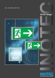
The data-line picture gives the<br />
general status per line. Each systems<br />
unique status is displayed on<br />
separate frames in the next level.<br />
Failures, i.e. lamp faults, are displayed<br />
in red.<br />
Em-light Systems<br />
Discharge protection Batt.-Operation System status<br />
F5 = Run manual<br />
Operation<br />
Failure<br />
F6 = Screen off<br />
1 2 3 4 5 6 FS 24V RTG B SL<br />
Charging failure<br />
Em-light Systems<br />
Systemtype<br />
Location<br />
Safe Mode<br />
manuel reset<br />
automat. FT<br />
Seminar room<br />
Luminaire location<br />
Workshop, mid-section<br />
Toilett-women, gf<br />
Workshop, left section<br />
Sales dept.<br />
512 04.04.01 13:13 1 1 Operation<br />
513 04.04.01 13:13 1 1 Operation<br />
514 04.04.01 13:14 1 1 Sub.-dist. failure<br />
515 04.04.01 16:25 1 1 Operation<br />
516 04.04.01 16:26 1 1 Sub.-dist. failure<br />
517 04.04.01 16:28 1 1 Funktiontest o.k.<br />
518 04.04.01 09:16 1 1 DT interrupted<br />
Funktiontest<br />
Durationtest<br />
Charge failure<br />
Transmission failure<br />
Manual reset<br />
Status<br />
Data line<br />
Log book<br />
No. Date Time Address System Event<br />
Total no. 520 Found 520 F10 = Setting<br />
Operation<br />
Failure Sub.-db<br />
Failure main-db<br />
Blocked<br />
ISO-failure<br />
Remote Control<br />
As an option INOTEC offers the<br />
programming of a building plan<br />
including all safety and emergency<br />
Operation<br />
luminaries. This feature allows easy<br />
localisation of failures and gives, after<br />
Batt.-Operation<br />
releasing a print-out, even service<br />
Failure personal unfamiliar with the site a<br />
simple and fast orientation possibility.<br />
Status<br />
Data line<br />
System address<br />
Kitchen<br />
Main dist.-board<br />
Corridor, first floor<br />
Stores<br />
RS blocks M-light<br />
RS blocks M-light and NM<br />
automat. DT<br />
Functiontest:<br />
Durationtest:<br />
Address System Setting<br />
From Date To D<br />
Em-light Systems<br />
Menue<br />
Enter<br />
Change<br />
Test<br />
Operation<br />
Seminar room<br />
Operation<br />
Seminar room<br />
Operation<br />
System 3<br />
Status<br />
Data line<br />
Status Operation<br />
Luminaire status<br />
Battery status<br />
Time delay<br />
8_min.<br />
CH1 CH2 CH3 CH4<br />
L N Stores L N L N L N<br />
Light Switch<br />
Indicator<br />
3,15 AT<br />
Functiontest:<br />
Durationtest:<br />
Functiontest:<br />
Durationtest:<br />
Toilett-men, gf<br />
Em Exit, corridor gf<br />
Delivery/packing<br />
Corridor basement<br />
Button<br />
Selection<br />
Button<br />
Button<br />
Back<br />
Button<br />
Em-light Systems<br />
Button<br />
Select<br />
Button<br />
Button<br />
Functions<br />
Button<br />
Data line<br />
Current: +0,0 A<br />
Voltage: 27,2 V<br />
Batterie circuit o.k.<br />
3,15 AT<br />
<strong>ELS</strong> - <strong>SV</strong><br />
Central monitoring and data-protection<br />
Information of INOTEC-standard <strong>SV</strong>PC<br />
can be found on page 13.<br />
Button<br />
Selection<br />
Button<br />
Button<br />
Back<br />
Button<br />
Com-Port<br />
Com-Port<br />
All stored log-book entries can be<br />
selected in various levels, i.e. display<br />
only lamp failures. Storage on disc,<br />
status- or luminaire failure print-out<br />
is always possible.<br />
Women<br />
Men<br />
Seminar room<br />
Help<br />
Office<br />
Engineering Sekrt.<br />
3,15 AT<br />
<strong>SV</strong> - PC software for<br />
max. 2 x 32 systems<br />
(<strong>ELS</strong> / LPS / CPS<br />
230V 50/60HZ 230V 50/60HZ<br />
Kitchen<br />
Sales dept.<br />
MD<br />
RTG<br />
interface<br />
Status<br />
Functiontest:<br />
Data line<br />
Durationtest:<br />
230V / AC<br />
Button output<br />
50 / 60 Hz<br />
Workshop<br />
PE N L<br />
1<br />
NLPE<br />
2 3<br />
Selection<br />
NLPE NLPE<br />
4<br />
NLPE<br />
3,15 AT<br />
Button<br />
Layout<br />
Button<br />
Back<br />
Button<br />
Help<br />
3,15 AT<br />
RTG<br />
interface
L1<br />
L2<br />
L3<br />
N<br />
PE<br />
UV/DB1<br />
<strong>ELS</strong> - <strong>SV</strong><br />
Central monitoring and data-protection<br />
DPÜ<br />
U<<br />
<strong>SV</strong>-central<br />
or PC<br />
L1<br />
L2<br />
L3<br />
N<br />
PE<br />
UV/DB1<br />
DPÜ<br />
U<<br />
From<br />
<strong>SV</strong>-central<br />
or PC<br />
<strong>SV</strong>-central for up to 32 systems<br />
L1<br />
L2<br />
L3<br />
N<br />
PE<br />
UV/DB1<br />
DPÜ<br />
U<<br />
L1<br />
L2<br />
L3<br />
N<br />
PE<br />
UV/DB1<br />
DPÜ<br />
U<<br />
L1<br />
L2<br />
L3<br />
N<br />
PE<br />
UV/DB1<br />
DPÜ<br />
U<<br />
L1<br />
L2<br />
L3<br />
N<br />
PE<br />
UV/DB1<br />
DPÜ<br />
U<<br />
No. Date Time<br />
L1<br />
L2<br />
L3<br />
N<br />
PE<br />
UV/DB1<br />
DPÜ<br />
U<<br />
Log book<br />
1 12.06.01 14:53 Functiontest failure<br />
System typ:<strong>ELS</strong> Address: 3<br />
Location:INOTEC Seminar room<br />
Current: -0,00 A Voltage: 0,0 V<br />
Module: 1<br />
Luminaire failure 4: Toilett Women<br />
2 12.06.01 15:00 Functiontest o.k.<br />
System typ:LPS 24 Address: 2<br />
Location:INOTEC Seminar room<br />
Current: -0,00 A Voltage: 0,0 V<br />
3 12.06.01 15:00 Functiontest o.k.<br />
System typ:<strong>ELS</strong>/<strong>SV</strong> Address: 3<br />
Location:INOTEC Seminar room<br />
Current: -0,00 A Voltage: 0,0 V<br />
4 12.06.01 15:27 Funktionstest failure<br />
System typ:CPS Address: 1<br />
Location:INOTEC Seminar room<br />
Current: -0,00 A Voltage: 0,0 V<br />
Circuit failures:<br />
Module: 1/2 Typ: SU/<strong>SV</strong> 2x3A<br />
Luminaire failure: Corridor<br />
Date: 26.07.2001 Time: 08:59:22 Page: 001<br />
L1<br />
L2<br />
L3<br />
N<br />
PE<br />
UV/DB1<br />
DPÜ<br />
U<<br />
L1<br />
L2<br />
L3<br />
N<br />
PE<br />
UV/DB1<br />
DPÜ<br />
U<<br />
15<br />
14<br />
13<br />
5<br />
4<br />
3<br />
2<br />
1<br />
15<br />
14<br />
13<br />
5<br />
4<br />
3<br />
2<br />
1<br />
L1<br />
L2<br />
L3<br />
N<br />
PE<br />
UV/DB1<br />
15<br />
14<br />
13<br />
DPÜ<br />
U<<br />
5<br />
4<br />
3<br />
2<br />
1<br />
15<br />
14<br />
13<br />
5<br />
4<br />
3<br />
2<br />
1<br />
9
10<br />
Reliable emergency lighting requires<br />
a well thought concept.<br />
Engineering projects always create the same<br />
questions on installation, cost efficiency<br />
and connection to building management<br />
systems coming to the emergency<br />
lighting design. INOTEC Sicherheitstechnik<br />
offers experience, know-how and<br />
outstanding technical products.<br />
To produce light and illuminate all exit<br />
paths sufficiently - these are the main<br />
features for emergency lighting<br />
systems in case of a mains fail<br />
condition or in an emergency<br />
situation. The building owner has to<br />
make certain, that these functions are<br />
perfectly working - even after years.<br />
Regular tests, maintenance and service<br />
are one backbone to ensure reliable<br />
function of all emergency lighting<br />
system components.<br />
Inline with national standards regulare<br />
visual checks, functiontests and system<br />
duration tests have to be performed.<br />
Test data and all relevant system<br />
information must be kept in a<br />
log-book.<br />
Lamps must be replaced and new<br />
batteries have to be installed.<br />
This can create, depending on the<br />
building size and the installed system,<br />
quite substantial costs. The long-term<br />
spending sometimes outrun the initial<br />
costs by a long way. This should be<br />
considered to find the most favourable<br />
solution when starting the project<br />
engineering.<br />
Batt.-Operation<br />
Operation<br />
Failure<br />
1 2 3 4 5 6 FS 24V RTG B SL<br />
To limit the expected costs and freeze<br />
the safety level at the highest point we<br />
use the INOTEC <strong>SV</strong>-monitoring system.<br />
Batt.-Operation<br />
Failure<br />
Charging failure<br />
Remote Control<br />
Emergency lighting systems and<br />
connected components bearing this<br />
prefix test and monitor themselves.<br />
The results can be displayed, printed or<br />
Operation<br />
stored.<br />
Menue<br />
Enter<br />
Change<br />
Test<br />
Luminaries+<br />
Em-light system<br />
kwh<br />
Visual test<br />
Routine<br />
test<br />
+ -<br />
Lamps<br />
Battery<br />
+ -<br />
CH1 CH2 CH3 CH4<br />
L N L N L N L N<br />
Maintenance<br />
Light Switch<br />
Indicator<br />
+ -<br />
3,15 AT<br />
<strong>ELS</strong> - <strong>SV</strong><br />
Advantages of monitored emergency lighting systems<br />
FT<br />
DT<br />
Investscosts<br />
Energy costs<br />
Labour costs<br />
visual check<br />
Labour costs<br />
FT/DT<br />
Material costs<br />
3,15 AT<br />
Labour costs<br />
for testing<br />
.<br />
230V / AC<br />
output<br />
50 / 60 Hz 1<br />
PE N L Maintenance NLPE<br />
2<br />
NLPE<br />
3<br />
NLPE<br />
4<br />
NLPE<br />
Labour costs<br />
costs<br />
3,15 AT<br />
3,15 AT<br />
Operation<br />
costs<br />
3,15 AT<br />
Lighting<br />
system<br />
costs
<strong>ELS</strong> - <strong>SV</strong><br />
Advantages of monitored emergency lighting systems<br />
To create the monitoring as efficient<br />
and cost effective as possible data<br />
lines to monitor the luminaries are not<br />
required.<br />
L<br />
N<br />
I I<br />
Each <strong>SV</strong>-emergency lighting system<br />
with all the connected luminaries will:<br />
monitor battery and charger<br />
permanently<br />
function test all components (e.g.<br />
lamps, electronic ballast's, system<br />
modules…) periodical<br />
automatically initiate the battery<br />
duration test (e.g. annually)<br />
and handle all events, information and<br />
results by<br />
logging and/or printout all system<br />
related data<br />
display any function failures and<br />
status information<br />
I<br />
Central Monitoring and data<br />
protection<br />
The availability of information on the<br />
systems location is sufficient for<br />
smaller installations - larger objects<br />
need a more complete and complex<br />
approach.<br />
Each <strong>SV</strong>-system offers the possibility to<br />
centralise all data and display/store<br />
the information at one location only.<br />
Smaller objects with a limited number<br />
of emergency lighting systems are<br />
ideal for the <strong>SV</strong>-Central (see page 9).<br />
Up to 16 systems can supervised<br />
including storage of all status/failure<br />
info, location of each connected<br />
luminaire and a logbook function. The<br />
included printer port allows selective<br />
or complete printout of data.<br />
The location text function for each<br />
luminaire is not possible if more<br />
systems (max. 32) are connected to<br />
one <strong>SV</strong>-Central.<br />
If a graphic display surface or the<br />
supervision of more than 16 panels<br />
including logbook function and<br />
individual luminaire location text is<br />
necessary, the <strong>SV</strong>-PC or a <strong>SV</strong>-PC<br />
software/interface package is the<br />
solution (see page 8).<br />
Building layout drawings with<br />
incorporated luminaire locations are<br />
available as well.<br />
Even the connection to a building<br />
management system or the<br />
transmission of information / service<br />
details of <strong>SV</strong>-systems via modem are<br />
part of the INOTEC product range<br />
(see page 13).<br />
Zone 2 Zone 1<br />
Location of emergency lighting<br />
systems<br />
To find a good and safe location for an<br />
emergency lighting system is part of<br />
every planning. National standards<br />
have to be observed.<br />
The functional safety is, apart from<br />
short cable runs, ease of access and<br />
good display visibility, a major focus<br />
point.<br />
The <strong>ELS</strong>-<strong>SV</strong> is designed for low load, to<br />
supply a small number of luminaries<br />
within a buildings fire zone.<br />
To install the <strong>ELS</strong> within the zone has<br />
the advantage, next to ease of access<br />
and short cable runs, of a high safety<br />
level for the complete building.<br />
Should a final end circuit fail, due to a<br />
local fire or a luminaire/line short<br />
circuit, no other circuit of the <strong>ELS</strong> will<br />
be effected.<br />
If the <strong>ELS</strong> is used to supply a circuit<br />
crossing various fire zone, or feeding<br />
luminaries in more than one zones,<br />
short circuits and failures of the system<br />
have an impact on the per-formance<br />
of luminaries in still safe or not<br />
endangered areas.<br />
The use of fire resistant cable is<br />
recommended for this application.<br />
E 30<br />
11
12<br />
DPÜ - Three Phase Monitor<br />
To detect phase- or circuit failures in general<br />
lighting sub-distribution panels<br />
With volt-free failure indication contact<br />
· LED-indication for L1, L2, L3<br />
· free selectable phase connections<br />
· 1 change-over contact<br />
· monitoring low voltage and mains failure<br />
in three-phase networks<br />
· for single-phase monitoring too<br />
acc. to IEC 255<br />
· for DIN rail mounting<br />
For the connection to INOTEC central- and<br />
group supply battery systems.<br />
Voltage: 230V/400V AC 50/60 Hz<br />
Threshold 0,85 x UN<br />
Perm. temp.: -20°C ... +60°C<br />
EMC protected to 55015<br />
Dimension: H =58, W = 17,5, D = 90(mm)<br />
MTB - Mimic Panel<br />
Three LED, controlled via volt-free <strong>ELS</strong><br />
contacts, indicate<br />
- mains operation<br />
- battery operation<br />
- sum-failure<br />
These LED-indicators are, even in case of a<br />
mains failure, supplied from the <strong>ELS</strong>-<strong>SV</strong>.<br />
Key switch with free programmable functions<br />
- maintained light On/Off<br />
- emergency light On/Off<br />
Protection class: IP54<br />
For wall mounting<br />
Dimensions: H=110, W=200, D=115 (mm)<br />
Power-Mode with INOTEC-EVG´s<br />
Programming for 1 h<br />
max discharge current 17Ah=10A / 34Ah=20A, Imax =6A circuit<br />
EVG-Type EVG 4-6 <strong>SV</strong> EVG 4-13 <strong>SV</strong> EVG 18<strong>SV</strong> N-EVG<br />
36/100<br />
Lamp T16 T16 T16 TC-DEL TC-EL TC-DEL T16 TC-DEL TC-DEL T26 T26<br />
Load 4W 6W 8W 10W 11W 13W 18W 18W 26W 32W 50W<br />
Light output ratio 70% 70% 70% 100% 100% 100% 100% 100% 100% 100% 100%<br />
1 Lamps<br />
2 Lamps<br />
3 Lamps<br />
4 Lamps<br />
5 Lamps<br />
6 Lamps<br />
7 Lamps<br />
8 Lamps<br />
9 Lamps<br />
10 Lamps<br />
11 Lamps<br />
12 Lamps<br />
13 Lamps<br />
14 Lamps<br />
15 Lamps<br />
45<br />
47<br />
58<br />
N-EVG<br />
58/100<br />
0,31 0,40 0,51 0,71 0,72 0,83 1,02 1,12 1,56 1,88 2,86<br />
0,49 0,67 0,88 1,28 1,31 1,52 1,91 2,10 2,97 3,63 5,59<br />
0,66 0,93 1,25 1,86 1,89 2,22 2,79 3,08 4,39 5,37 - - -<br />
0,83 1,19 1,62 2,43 2,47 2,91 3,67 4,06 5,81 - - - - - -<br />
1,00 1,45 1,99 3,00 3,05 3,60 4,55 5,04 - - - - - - - - -<br />
1,18 ,72 2,36 3,57 3,64 4,29 5,44 - - - - - - - - - - - -<br />
1,35 1,98 2,73 4,14 4,22 4,98 - - - - - - - - - - - - - - -<br />
1,53 2,24 3,10 4,72 4,80 5,68 - - - - - - - - - - - - - - -<br />
1,70 2,50 3,47 5,29 5,39 - - - - - - - - - - - - - - - - - -<br />
1,87 2,77 3,84 5,86 5,97 - - - - - - - - - - - - - - - - - -<br />
2,05 3,03 4,22 - - - - - - - - - - - - - - - - - - - - - - - -<br />
2,22 3,29 4,59 - - - - - - - - - - - - - - - - - - - - - - - -<br />
2,37 3,55 4,96 - - - - - - - - - - - - - - - - - - - - - - - -<br />
2,56 3,82 5,33 - - - - - - - - - - - - - - - - - - - - - - - -<br />
2,74 4,08 5,70 - - - - - - - - - - - - - - - - - - - - - - - -<br />
<strong>ELS</strong>/<strong>SV</strong><br />
Components and technical data<br />
MTB - Mimic Panel<br />
Three LED, controlled via volt-free <strong>ELS</strong><br />
contacts, indicate<br />
- mains operation<br />
- battery operation<br />
- sum-failure<br />
These LED-indicators are, even in case of a<br />
mains failure, supplied from the <strong>ELS</strong>-<strong>SV</strong>.<br />
Key switch with free programmable functions<br />
- maintained light On/Off<br />
- emergency light On/Off<br />
Protection class: IP20<br />
For recessed wall mounting<br />
Dimensions: ø 90 (mm), D = 6,5 mm<br />
Notlicht<br />
Betrieb<br />
Störung Batt.-Betrieb<br />
Ein<br />
17,5 90<br />
200 70 6,5<br />
115<br />
165<br />
90<br />
INOTEC<br />
Safe-Mode with INOTEC-EVG`s<br />
Programming for 3 h<br />
max discharge current 17Ah=4,3A/34Ah=8,6A<br />
Aus<br />
74<br />
EVG 4-6 <strong>SV</strong> EVG 4-13 <strong>SV</strong> EVG 18<strong>SV</strong><br />
T16 T16 T16 TC-DEL TC-EL TC-DEL T16 TC-DEL<br />
4W 6W 8W 10W 11W 13W 18W 18W<br />
32% 32% 32% 50% 50% 50% 50% 50%<br />
0,24 0,28 0,31 0,43 0,43 0,48 0,58 0,63<br />
0,34 0,41 0,48 0,71 0,73 0,82 1,02 1,12<br />
0,44 0,55 0,65 1,00 1,02 1,16 1,46 1,61<br />
0,54 0,68 0,82 1,28 1,32 1,50 1,91 2,10<br />
0,64 0,82 0,98 1,57 1,61 1,84 2,35 2,59<br />
0,74 0,95 1,15 1,86 1,91 2,18 2,79 - - -<br />
0,84 1,09 1,32 2,14 2,20 2,52 3,23 - - -<br />
0,94 1,22 1,49 2,43 2,49 2,86 3,67 - - -<br />
1,04 1,36 1,66 2,71 2,79 3,20 - - - - - -<br />
1,14 1,49 1,83 3,00 3,08 3,55 - - - - - -<br />
1,24 1,63 2,00 3,29 3,38 3,89 - - - - - -<br />
1,34 ,76 2,17 3,57 3,67 - - - - - - - - -<br />
1,44 1,90 2,34 3,86 3,96 - - - - - - - - -<br />
1,54 2,03 2,50 - - - - - - - - - - - - - - -<br />
1,64 2,17 2,67 - - - - - - - - - - - - - - -
<strong>ELS</strong>/<strong>SV</strong><br />
Komponenten zur Überwachung und Datensicherung mit Technischen Daten<br />
<strong>SV</strong> - Central<br />
-Free programmable microprocessor<br />
controlled unit for max. 32 emergency<br />
lighting systems, c/w<br />
- four line liquid crystal display for status and<br />
failure info in plain text<br />
- four status / failure display LED<br />
- manual release / interruption of function<br />
(FT) - and battery duration (BT) test<br />
- automatic release of FT and BT<br />
- data bus (RTG) terminals 2,5mm²<br />
- suitable for <strong>ELS</strong>, LPS and CPS<br />
- programming, interrogation and supervision<br />
of all connected systems<br />
- keyboard interface for programming<br />
- centronics interface for external printers<br />
- logbook function; for up to 16 <strong>ELS</strong>-<strong>SV</strong> with<br />
individual luminaire location text<br />
- battery back-up during mains failure<br />
Displayed information covers<br />
- mains operation<br />
- battery operation<br />
- sum-failure<br />
- charge failure<br />
- function test running<br />
- battery duration test running<br />
- blocked system<br />
- printer off-line<br />
- printing failure<br />
- luminaire failure for each individual system<br />
Active manual release / interruption of<br />
- function test<br />
- battery duration test for all connected<br />
systems and the complete data line.<br />
<strong>SV</strong>-Central, panel mounting, IP 20<br />
cut-out 136 x 90 (mm),<br />
dimensions: H=97, W=145, D=155 (mm)<br />
97<br />
<strong>SV</strong>-Central, for wall mounting, IP 54<br />
dimensions : H=237, W=255, D=250 (mm)<br />
237<br />
145<br />
136<br />
255<br />
85<br />
155<br />
235<br />
90<br />
<strong>SV</strong>PC Software / Interface Package<br />
RTG-interface and PC-software for monitoring<br />
up to 32 emergency lighting systems <strong>ELS</strong>, LPS<br />
or CPS on one data line.<br />
Software Anforderungen: Windows 9X / NT/<br />
2000 / XP, serial interface, monitor 640 x 480<br />
pixel, Pentium prozessor, 8 MB-RAM, hard drive<br />
2 GB.<br />
The interface will be delivered with 230 V<br />
mains cable, Euro-plug, RTG data line and serial<br />
interface cable with plug.<br />
The software is used to monitor, display, store,<br />
download or print all relevant data of the<br />
complete emergency lighting installation.<br />
The configuration of each system and the<br />
complete installation is stored along with a<br />
complete log book of all events / failures.<br />
The log book contains details as location,<br />
failure type / date / time and allows selected<br />
visualising or partial / complete printing.<br />
The software automatically releases the<br />
required function- and battery duration test.<br />
Programming the <strong>SV</strong>PC allows to download<br />
the information (luminaire location, switching<br />
modes…) to each installed emergency lighting<br />
system (CPS,LPS,BNS).<br />
<strong>SV</strong>PC Software Options<br />
<strong>SV</strong>PC software "building drawing", to<br />
program and display building plans with<br />
location of emergency luminaires and<br />
emergency lighting systems.<br />
<strong>SV</strong>PC "timer" software, to program periods<br />
where the emergency lighting system is<br />
blocked (during unoccupied periods like<br />
weekends, holidays, bank holidays or night<br />
time) to save energy.<br />
<strong>SV</strong>PC "bms" software, for data transmission of<br />
24V interface contact details to building<br />
management system.<br />
<strong>SV</strong>PC "modem" hardware/software-option to<br />
gain access to log book and current system<br />
status info via phone, Advantageous for central<br />
service points.<br />
J-ET 9/24 <strong>SV</strong><br />
Constant current luminaire module for the<br />
supply and monitoring of LEDs.<br />
Light output in mains adjustable.<br />
With easy accessible address-switch and<br />
JOKER function, switch to select<br />
maintained or non-maintained mode and<br />
individual light source failure detection<br />
For the connection to INOTEC central- and<br />
group supply battery systems.<br />
Input voltage:<br />
230V AC 50/60 Hz<br />
220V DC ±20 %<br />
Output voltage: 24V DC<br />
Output current: 320 mA constant<br />
Perm. temp.: -15°C ... +50°C<br />
EMC protected to EN 55015<br />
Dimension: H = 28, W = 40, D = 90(mm)<br />
Qty. LED Bat.-current<br />
Luxeon consumed<br />
1 15 mA<br />
2 20 mA<br />
3 25 mA<br />
4 30 mA<br />
5 35 mA<br />
Load<br />
P / W<br />
3,1<br />
4,2<br />
5,3<br />
6,4<br />
7,6<br />
13
14<br />
J-EVG 4-6 <strong>SV</strong><br />
J-EVG 4-13 <strong>SV</strong><br />
J-EVG 18 <strong>SV</strong><br />
Compensated high frequency electronic<br />
ballast<br />
for fluorescent and compact fluorescent<br />
lamps TL/TC/TCD-EL 4-18 W, with easy<br />
accessible address switch, JOKER function<br />
and individual lamp monitoring.<br />
The JOKER function allows luminaries to be<br />
operated in maintained and<br />
non-maintained mode on the same final<br />
end circuit.<br />
Automatic deactivation of electronics in<br />
case of lamp failure.<br />
Suitable for emergency lighting systems<br />
to EN 50171 / EN 50172.<br />
Designed to be installed inside of<br />
luminaires.<br />
For the connection to INOTEC low poweror<br />
central power battery systems like <strong>ELS</strong><br />
or CPS.<br />
Voltage:<br />
230V AC 50/60 Hz<br />
220V DC ±20 %<br />
Perm. temp.: -15°C ... +50°C<br />
EMC protected to EN 55015<br />
40 4<br />
3 28<br />
<strong>ELS</strong>/<strong>SV</strong><br />
<strong>Electronic</strong> ballast's and <strong>SV</strong>-luminaire modules with JOKER-Technology<br />
J-EVG 4-6 <strong>SV</strong>/S<br />
J-EVG 4-13 <strong>SV</strong>/S<br />
J-EVG 18 <strong>SV</strong>/S<br />
Compensated high frequency electronic<br />
ballast<br />
for fluorescent and compact fluorescent<br />
lamps TL/TC/TCD-EL 4-18 W, with easy<br />
accessible address switch, JOKER function<br />
and individual lamp monitoring. This<br />
electronic ballast features a sense-input<br />
or an inverted phase monitor too.<br />
J-EVG 4-6 <strong>SV</strong> designed for low power loss<br />
at 4 Watt.<br />
The JOKER/S function allows luminaires to<br />
be operated in maintained, non-maintained<br />
and switched mode on the same final end<br />
circuit. Automatic deactivation of<br />
electronics in case of lamp failure.<br />
Suitable for emergency lighting systems<br />
to EN 50171 / EN 50172.<br />
Designed to be installed inside of<br />
luminaires. For the connection to INOTEC<br />
low power- or central power battery<br />
systems like <strong>ELS</strong> or CPS.<br />
Voltage:<br />
230V AC 50/60 Hz<br />
220V DC ±20 %<br />
Perm. temp.: -15°C ... +50°C<br />
EMC protected to EN 55015<br />
Individual lamp monitoring<br />
Component Type Joker technology Load Sense-input Treshhold Order number<br />
J-EVG 4-6 <strong>SV</strong> EVG yes 4-6W no 860008<br />
J-EVG 4-13 <strong>SV</strong> EVG yes 4-13W no 860004<br />
J-EVG 18 <strong>SV</strong> EVG yes 18W no 861003<br />
J-EVG 4-6 <strong>SV</strong>/S EVG yes 4-6W yes 860010<br />
J-EVG 4-13 <strong>SV</strong>/S EVG yes 4-13W yes 860005<br />
J-EVG 18 <strong>SV</strong>/S EVG yes 18W yes 861004<br />
<strong>SV</strong> Modul.1 Modul no 5-120W no<br />
Failure O.k<br />
< 10mA > 20mA 851001<br />
<strong>SV</strong> Modul.2 Modul no 20-300W no < 45mA > 70mA 851003<br />
J-<strong>SV</strong> Modul/S Modul yes 5-120W yes < 10mA > 20mA 851002<br />
J-<strong>SV</strong> Modul.2/S Modul yes 20-300W yes < 45mA > 70mA 851004<br />
J-<strong>SV</strong> Modul.3/S Modul yes 2-30W yes < 8mA > 12mA 851025<br />
J-<strong>SV</strong> Modul.4/S Modul yes 18-120W yes < 45mA > 70mA 851029<br />
J-<strong>SV</strong> Modul.L/S Modul yes 5-120W yes < 10mA > 20mA 851026<br />
J-<strong>SV</strong>-Modul/S<br />
J-<strong>SV</strong>-Modul.2/S<br />
J-<strong>SV</strong>-Modul.3/S<br />
J-<strong>SV</strong>-Modul.4/S<br />
J-<strong>SV</strong>-Modul.L/S<br />
Single luminaire monitoring module<br />
for fluorescent- (T16/T5…) compact<br />
fluorescent, halogen and incandescent<br />
lamps. With easy accessible address switch,<br />
JOKER function and individual lamp monitoring.<br />
This module features a sense-input or<br />
an inverted phase monitor too.<br />
The JOKER/S function allows luminaries to<br />
be operated via these J-<strong>SV</strong>-modules in<br />
maintained, non-maintained and switched<br />
mode on the same final end circuit.<br />
Suitable for emergency lighting systems to<br />
EN 50171 / EN 50172.<br />
Designed to be installed inside of luminaries.<br />
For the connection to INOTEC low<br />
power- or central power battery systems<br />
like <strong>ELS</strong> or CPS.<br />
Voltage:<br />
230 V AC, 50/60 Hz<br />
220 V DC, ±20 %<br />
Perm. temp.: -15°C ... +50°C<br />
EMC protected to EN 55015<br />
4,2<br />
4,2<br />
J-EVG 4-6/<strong>SV</strong><br />
J-EVG 4-13/<strong>SV</strong><br />
J-EVG 18/<strong>SV</strong><br />
240,4<br />
J-Modul/S<br />
J-<strong>SV</strong> Modul/S<br />
J-ET 9/24 <strong>SV</strong><br />
80<br />
90<br />
J-EVG 4-6/<strong>SV</strong>-S<br />
J-EVG 4-13/<strong>SV</strong>-S<br />
J-EVG 18/<strong>SV</strong>-S<br />
80<br />
90<br />
J-<strong>SV</strong> Modul.L/S<br />
J-<strong>SV</strong>-Modul.L/S<br />
235,4<br />
249,4<br />
40 4<br />
3 30<br />
17,9<br />
7<br />
26,4
<strong>ELS</strong> - <strong>SV</strong><br />
Specification text and technical data<br />
850<br />
785<br />
INOTEC <strong>ELS</strong>-<strong>SV</strong> emergency lighting system<br />
with Joker-technology, for the supply and<br />
monitoring of up to 60 safety- or exit<br />
luminaries. Each outgoing circuit is for 15<br />
luminaries in maintained, non-maintained or<br />
switched maintained mode either mixed or in<br />
one mode on the line. The <strong>ELS</strong>/<strong>SV</strong> system<br />
incorporates:<br />
- battery for 1h or 3h duration<br />
- charger<br />
- 4 converters, each suitable for 15 monitored<br />
luminaries, max. converter load 120W.<br />
- control module with two-line liquid crystal<br />
display for status information in national<br />
language<br />
- light-switch-monitor and Joker- technology<br />
- delay on mains return option (0 - 15 min)<br />
Mains supply: 230/240 V AC<br />
Output voltage mains: 230/240 V AC<br />
Output voltage battery: 220 V DC<br />
Rated duration: 1h or 3h<br />
Protection class I, protection category IP 40<br />
Max. permissible ambient temp. : -5°C to +40°C<br />
Weight:<br />
With 17 Ah batteries 32kg<br />
With 34 Ah batteries 46kg<br />
325 100<br />
400<br />
Mechanical design:<br />
Powder coated (RAL 7032) sheet steel housing<br />
with separate battery compartment.<br />
OCTA-aluminium profile door with clear<br />
polycarbonate inlay, lhs door hinges. Separate<br />
internal covers for battery-, terminal- and<br />
electronic compartment. Block diagram with<br />
technical data on electronic compartment<br />
cover. Housing with internal earth contacts.<br />
Cable inlets top. Battery and terminal /<br />
electronics compartment with ventilation<br />
slots. The <strong>ELS</strong>-<strong>SV</strong> is suitable for wall mounting<br />
(fixing details 325 x 765 mm; hole ø 6 mm).<br />
Total ( H x W x D) 870 x 420 x 105 mm<br />
870<br />
420<br />
105<br />
Electrical design:<br />
Supply- (max. 1 x 4 mm² ) and outgoing<br />
circuits (max. 2 x 2,5 mm² ) are prewired to<br />
terminals located on the central terminal rail.<br />
The cable inlets on the top of the enclosure<br />
are predrilled and closed with rubber blind<br />
plugs M20. Battery- and mains fuses for<br />
charger and each converter are included.<br />
Creepage- and clearance distances are in line<br />
to IEC standards.<br />
Three volt-free contacts (3xno) for the remote<br />
failure/status indication are available.<br />
Maintained and non-maintained circuits can<br />
be freely programmed via the control module.<br />
Mixed operation of maintained-,<br />
non-maintained- and switched maintained<br />
luminaries on any final end circuit<br />
(Joker-technology) is always possible.<br />
24 V monitoring loop<br />
Each <strong>ELS</strong>-<strong>SV</strong> has the terminals to connect<br />
external phase monitors (DPÜ). They are used<br />
to monitor sub-distributions for general<br />
lighting or individual lighting circuits. The max.<br />
cable run allowed is 2000m with 1,5 mm².<br />
Charger 3A:<br />
Temperature controlled constant voltage<br />
charger, current limited, with boost charge<br />
function. Battery voltage monitoring and time<br />
-controlled trickle charge function. Chargers<br />
failures are visual via a red "charge failure" LED<br />
on the left side of the display area.<br />
Recharge time:
INOTEC Sicherheitstechnik GmbH<br />
Am Buschgarten 17<br />
D - 59 469 Ense<br />
Tel 0 29 38/97 30-0<br />
Fax 0 29 38/97 30-29<br />
info@inotec-licht.de<br />
www.inotec-licht.de<br />
Sicherheitstechnik GmbH<br />
Ausgabe 2007/01